EP0768392B1 - Crystal manufacturing apparatus - Google Patents
Crystal manufacturing apparatus Download PDFInfo
- Publication number
- EP0768392B1 EP0768392B1 EP96402139A EP96402139A EP0768392B1 EP 0768392 B1 EP0768392 B1 EP 0768392B1 EP 96402139 A EP96402139 A EP 96402139A EP 96402139 A EP96402139 A EP 96402139A EP 0768392 B1 EP0768392 B1 EP 0768392B1
- Authority
- EP
- European Patent Office
- Prior art keywords
- crystal
- transparent plate
- insulation member
- image
- crucible
- Prior art date
- Legal status (The legal status is an assumption and is not a legal conclusion. Google has not performed a legal analysis and makes no representation as to the accuracy of the status listed.)
- Expired - Lifetime
Links
- 239000013078 crystal Substances 0.000 title claims description 145
- 238000004519 manufacturing process Methods 0.000 title claims description 8
- 238000009413 insulation Methods 0.000 claims description 36
- 239000000155 melt Substances 0.000 claims description 18
- 229910052594 sapphire Inorganic materials 0.000 claims description 9
- 239000010980 sapphire Substances 0.000 claims description 9
- VYPSYNLAJGMNEJ-UHFFFAOYSA-N Silicium dioxide Chemical compound O=[Si]=O VYPSYNLAJGMNEJ-UHFFFAOYSA-N 0.000 claims description 8
- 230000007246 mechanism Effects 0.000 description 22
- 238000000034 method Methods 0.000 description 17
- 238000005070 sampling Methods 0.000 description 16
- 238000005286 illumination Methods 0.000 description 15
- 239000000463 material Substances 0.000 description 15
- 239000007789 gas Substances 0.000 description 14
- 230000005855 radiation Effects 0.000 description 13
- 238000005259 measurement Methods 0.000 description 12
- 230000003287 optical effect Effects 0.000 description 12
- 239000003365 glass fiber Substances 0.000 description 10
- 238000012545 processing Methods 0.000 description 10
- 230000006399 behavior Effects 0.000 description 6
- 238000001816 cooling Methods 0.000 description 6
- 239000007788 liquid Substances 0.000 description 6
- 239000000835 fiber Substances 0.000 description 5
- 239000007787 solid Substances 0.000 description 5
- 238000010408 sweeping Methods 0.000 description 5
- IJGRMHOSHXDMSA-UHFFFAOYSA-N Atomic nitrogen Chemical compound N#N IJGRMHOSHXDMSA-UHFFFAOYSA-N 0.000 description 4
- 229910009203 Y-Ba-Cu-O Inorganic materials 0.000 description 4
- QVGXLLKOCUKJST-UHFFFAOYSA-N atomic oxygen Chemical compound [O] QVGXLLKOCUKJST-UHFFFAOYSA-N 0.000 description 4
- 230000015572 biosynthetic process Effects 0.000 description 4
- 238000006243 chemical reaction Methods 0.000 description 4
- 238000010276 construction Methods 0.000 description 4
- 239000001301 oxygen Substances 0.000 description 4
- 229910052760 oxygen Inorganic materials 0.000 description 4
- 239000010453 quartz Substances 0.000 description 4
- 239000002887 superconductor Substances 0.000 description 4
- PNEYBMLMFCGWSK-UHFFFAOYSA-N aluminium oxide Inorganic materials [O-2].[O-2].[O-2].[Al+3].[Al+3] PNEYBMLMFCGWSK-UHFFFAOYSA-N 0.000 description 3
- 238000013461 design Methods 0.000 description 3
- 230000000694 effects Effects 0.000 description 3
- 230000006911 nucleation Effects 0.000 description 3
- 238000010899 nucleation Methods 0.000 description 3
- XKRFYHLGVUSROY-UHFFFAOYSA-N Argon Chemical compound [Ar] XKRFYHLGVUSROY-UHFFFAOYSA-N 0.000 description 2
- 238000010438 heat treatment Methods 0.000 description 2
- 239000012774 insulation material Substances 0.000 description 2
- 229910052757 nitrogen Inorganic materials 0.000 description 2
- 238000011160 research Methods 0.000 description 2
- 239000000758 substrate Substances 0.000 description 2
- 230000001360 synchronised effect Effects 0.000 description 2
- 239000010409 thin film Substances 0.000 description 2
- XLYOFNOQVPJJNP-UHFFFAOYSA-N water Substances O XLYOFNOQVPJJNP-UHFFFAOYSA-N 0.000 description 2
- 239000000853 adhesive Substances 0.000 description 1
- 230000001070 adhesive effect Effects 0.000 description 1
- 229910052786 argon Inorganic materials 0.000 description 1
- 230000005494 condensation Effects 0.000 description 1
- 238000009833 condensation Methods 0.000 description 1
- 239000000498 cooling water Substances 0.000 description 1
- 230000007797 corrosion Effects 0.000 description 1
- 238000005260 corrosion Methods 0.000 description 1
- 229910052593 corundum Inorganic materials 0.000 description 1
- 230000003247 decreasing effect Effects 0.000 description 1
- 230000001419 dependent effect Effects 0.000 description 1
- 238000011161 development Methods 0.000 description 1
- 238000010586 diagram Methods 0.000 description 1
- 238000007599 discharging Methods 0.000 description 1
- 239000012212 insulator Substances 0.000 description 1
- 230000014759 maintenance of location Effects 0.000 description 1
- 239000000203 mixture Substances 0.000 description 1
- 238000012544 monitoring process Methods 0.000 description 1
- 238000005192 partition Methods 0.000 description 1
- 230000002093 peripheral effect Effects 0.000 description 1
- 230000002035 prolonged effect Effects 0.000 description 1
- 230000000644 propagated effect Effects 0.000 description 1
- 239000004065 semiconductor Substances 0.000 description 1
- 229910052710 silicon Inorganic materials 0.000 description 1
- 239000010703 silicon Substances 0.000 description 1
- 229910001220 stainless steel Inorganic materials 0.000 description 1
- 239000010935 stainless steel Substances 0.000 description 1
- 239000000126 substance Substances 0.000 description 1
- 229910001845 yogo sapphire Inorganic materials 0.000 description 1
- 229910052727 yttrium Inorganic materials 0.000 description 1
- VWQVUPCCIRVNHF-UHFFFAOYSA-N yttrium atom Chemical compound [Y] VWQVUPCCIRVNHF-UHFFFAOYSA-N 0.000 description 1
Images




Classifications
-
- C—CHEMISTRY; METALLURGY
- C30—CRYSTAL GROWTH
- C30B—SINGLE-CRYSTAL GROWTH; UNIDIRECTIONAL SOLIDIFICATION OF EUTECTIC MATERIAL OR UNIDIRECTIONAL DEMIXING OF EUTECTOID MATERIAL; REFINING BY ZONE-MELTING OF MATERIAL; PRODUCTION OF A HOMOGENEOUS POLYCRYSTALLINE MATERIAL WITH DEFINED STRUCTURE; SINGLE CRYSTALS OR HOMOGENEOUS POLYCRYSTALLINE MATERIAL WITH DEFINED STRUCTURE; AFTER-TREATMENT OF SINGLE CRYSTALS OR A HOMOGENEOUS POLYCRYSTALLINE MATERIAL WITH DEFINED STRUCTURE; APPARATUS THEREFOR
- C30B29/00—Single crystals or homogeneous polycrystalline material with defined structure characterised by the material or by their shape
- C30B29/10—Inorganic compounds or compositions
- C30B29/16—Oxides
- C30B29/22—Complex oxides
-
- C—CHEMISTRY; METALLURGY
- C30—CRYSTAL GROWTH
- C30B—SINGLE-CRYSTAL GROWTH; UNIDIRECTIONAL SOLIDIFICATION OF EUTECTIC MATERIAL OR UNIDIRECTIONAL DEMIXING OF EUTECTOID MATERIAL; REFINING BY ZONE-MELTING OF MATERIAL; PRODUCTION OF A HOMOGENEOUS POLYCRYSTALLINE MATERIAL WITH DEFINED STRUCTURE; SINGLE CRYSTALS OR HOMOGENEOUS POLYCRYSTALLINE MATERIAL WITH DEFINED STRUCTURE; AFTER-TREATMENT OF SINGLE CRYSTALS OR A HOMOGENEOUS POLYCRYSTALLINE MATERIAL WITH DEFINED STRUCTURE; APPARATUS THEREFOR
- C30B15/00—Single-crystal growth by pulling from a melt, e.g. Czochralski method
- C30B15/20—Controlling or regulating
- C30B15/22—Stabilisation or shape controlling of the molten zone near the pulled crystal; Controlling the section of the crystal
- C30B15/26—Stabilisation or shape controlling of the molten zone near the pulled crystal; Controlling the section of the crystal using television detectors; using photo or X-ray detectors
-
- Y—GENERAL TAGGING OF NEW TECHNOLOGICAL DEVELOPMENTS; GENERAL TAGGING OF CROSS-SECTIONAL TECHNOLOGIES SPANNING OVER SEVERAL SECTIONS OF THE IPC; TECHNICAL SUBJECTS COVERED BY FORMER USPC CROSS-REFERENCE ART COLLECTIONS [XRACs] AND DIGESTS
- Y10—TECHNICAL SUBJECTS COVERED BY FORMER USPC
- Y10T—TECHNICAL SUBJECTS COVERED BY FORMER US CLASSIFICATION
- Y10T117/00—Single-crystal, oriented-crystal, and epitaxy growth processes; non-coating apparatus therefor
- Y10T117/10—Apparatus
- Y10T117/1024—Apparatus for crystallization from liquid or supercritical state
- Y10T117/1032—Seed pulling
-
- Y—GENERAL TAGGING OF NEW TECHNOLOGICAL DEVELOPMENTS; GENERAL TAGGING OF CROSS-SECTIONAL TECHNOLOGIES SPANNING OVER SEVERAL SECTIONS OF THE IPC; TECHNICAL SUBJECTS COVERED BY FORMER USPC CROSS-REFERENCE ART COLLECTIONS [XRACs] AND DIGESTS
- Y10—TECHNICAL SUBJECTS COVERED BY FORMER USPC
- Y10T—TECHNICAL SUBJECTS COVERED BY FORMER US CLASSIFICATION
- Y10T117/00—Single-crystal, oriented-crystal, and epitaxy growth processes; non-coating apparatus therefor
- Y10T117/10—Apparatus
- Y10T117/1024—Apparatus for crystallization from liquid or supercritical state
- Y10T117/1032—Seed pulling
- Y10T117/1068—Seed pulling including heating or cooling details [e.g., shield configuration]
-
- Y—GENERAL TAGGING OF NEW TECHNOLOGICAL DEVELOPMENTS; GENERAL TAGGING OF CROSS-SECTIONAL TECHNOLOGIES SPANNING OVER SEVERAL SECTIONS OF THE IPC; TECHNICAL SUBJECTS COVERED BY FORMER USPC CROSS-REFERENCE ART COLLECTIONS [XRACs] AND DIGESTS
- Y10—TECHNICAL SUBJECTS COVERED BY FORMER USPC
- Y10T—TECHNICAL SUBJECTS COVERED BY FORMER US CLASSIFICATION
- Y10T117/00—Single-crystal, oriented-crystal, and epitaxy growth processes; non-coating apparatus therefor
- Y10T117/10—Apparatus
- Y10T117/1024—Apparatus for crystallization from liquid or supercritical state
- Y10T117/1076—Apparatus for crystallization from liquid or supercritical state having means for producing a moving solid-liquid-solid zone
- Y10T117/1088—Apparatus for crystallization from liquid or supercritical state having means for producing a moving solid-liquid-solid zone including heating or cooling details
Definitions
- the present invention relates in general to a pulling-type crystal manufacturing apparatus, and relates in particular to a crystal pulling apparatus suitable for use in producing a crystal of a high temperature oxide superconductor material.
- Crystal pulling is an effective technique of growing a large single crystal under controlled the conditions of growth.
- the crystal pulling apparatus broadly comprises a furnace section and a drive mechanism for pulling up a crystal.
- the method of operation is broadly as follows: a seed crystal is attached to the bottom end of a pulling rod located within the furnace section, next the seed crystal is made to touch the surface of a molten solution of the superconductor material held in a crucible, and the seed crystal is rotated and pulled up so that a crystal can be grown on the seed crystal.
- a small peek window is provided on the side wall of the furnace section to permit observation of the growth behavior of the crystal. If it is necessary to measure the dimension of the grown crystal, measurements are taken from an image of the crystal produced on a monitoring screen provided for the apparatus.
- the conventional apparatus is designed so as to insulate the upper portion the furnace section for retention of heat, and consequently, it has been difficult to increase the temperature gradient. It follows therefore that the conventional apparatus inherently presented a problem that the stray crystals nucleated around the growing single crystal gradually increase in number during the subsequent growth process of the single crystal.
- the document EP-A-0 417 948 discloses a crystal growth apparatus with an insulation member disposed on the side of a crucible in a manner such that a heater is between the crucible and the insulation member.
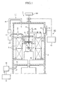
- Figure 1 is a cross sectional side view of a first embodiment of a crystal growing apparatus of the present invention.
- Figure 2 is a cross sectional side view of a partition plate of the crystal growing apparatus.
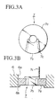
- Figure 3A is a plan view of a first transparent plate of the apparatus.
- Figure 3B is a cross sectional view of the transparent plate.
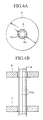
- Figure 4A is an enlarged view of the portion where the pulling rod passes through the transparent plate.
- Figure 4B is a cross sectional view of the section shown in Figure 3A.
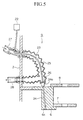
- Figure 5 is a cross sectional side view of the crystal illumination device of the apparatus.
- Figure 6 is a block diagram of the crystal size measurement device.
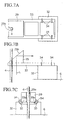
- Figure 7A is a plan view of a support structure for a quartz prism of the apparatus.
- Figure 7B is a side view of the structure shown in Figure 7A.
- Figure 7C is a front view of the structure shown in Figure 7A.
- Figure 8 is a flowchart for crystal size determination process.
- Figure 9 is a portion of the flowchart shown in Figure 8 which determines the perimeter length.
- Figure 10A-10D are schematic drawing to explain the process of determining the perimeter length.
- the object is achieved in a crystal manufacturing apparatus comprising :
- a crystal illumination mechanism to illuminate the growing crystal, and crystal size determination mechanism to measure the side of the crystal when the shape is non-circular.
- the actual elements of the crystal illumination mechanism are a visible light source for emitting visible light ; a glass fiber transparent to said visible light, whose one end is in optical contact with said light source ; an illumination plate attached to other end of said glass fiber ; a sapphire fiber optically aligned with said illumination plate in an non-contacting manner to transmit said visible light; and a cooling tube surrounding said glass fiber for permitting water to circulate for cooling said glass fiber.
- the actual elements of the crystal size determination mechanism are an optical path changing means for altering an optical path of infrared radiation emitted from said growing crystal and said melt and an optical path of said visible light and passed though said transparent plate; a crystal size determination device for measuring and determining dimensions of said growing crystal by receiving infrared radiation and reflected light which passes through said optical path changing device to form an image of said growing crystal, outputs said image and measurement data of said growing crystal.
- the optical path changing means can be made of a prism having a slit for allowing the pull rod to pass through.
- the actual construction of the crystal size determination mechanism are an electro-optic recording device for receiving infrared radiation and reflected light which have passed through said optical path changing means so as to form an image of said growing crystal; an image processing section for sampling said image of said growing crystal in synchronization with a rotational speed of said pulling rod so as to form a still image of said growing crystal; and an output device for outputting results of image processing produced by said image processing section. It is also permissible to provide a phase angle setting device for setting a phase angle for a revolving growing crystal.
- the crystal size determination device may utilize an infrared transmitting filter between the optical changing device and the recording device such as a camera.
- An ambient atmosphere sweeping device may be provided for admitting an ambient atmosphere from a top region and discharging from a bottom region of said chamber.
- said first transparent plate consists of a U-shaped first piece and a fan-shaped second piece having a pick-up bar.
- the feature of the present apparatus is that thermal distribution is carefully controlled.
- the crucible exterior is surrounded with a heater, and the top region is covered with an insulation member having a center hole, therefore, during the crystal growing operation, there is considerable heat loss through the transparent plate covering the center hole of the insulation member.
- the apparatus compensates for the heat loss and achieves the required temperature for crystal growth by supplying the lost heat through the heater, thereby compensating a large heat loss through the transparent plates by a large quantity of heat from the heater. Therefore, the temperatures of the outer periphery of the crucible and the bottom region of the insulation member rise compared with the center region of the crucible, thus producing a large temperature gradient in the melt contained in the crucible.
- the transparent plates serve as peek window to enable observation of the behavior of the growing crystal.
- Additional features include the novel crystal illumination and crystal size determination mechanisms to enable determination of the size of the growing crystal even when the shape is non-circular, by utilizing infrared radiation emitted from the high temperature crystal and the melt or visible light generated from the illumination device and reflected from the crystal. For example, when it is necessary to measure the perimeter length of a square-shaped crystal, the image processing section samples the crystal image in synchronization with the rotational speed of the growing crystal. By doing so, it becomes possible to generate a still image of the square-shaped growing crystal, and the still image can be numerically processed to compute the perimeter length.
- the apparatus when the apparatus is provided with ambient atmosphere sweeping means, the ambient atmosphere flows from the top region to the bottom region of the apparatus.
- the atmosphere passing downwards through the space between the pull rod and the center hole of the transparent plates, the rotational action of the fins makes the gas to flow from the center region toward the outer region of the plates underneath the plates. This action of the gas flow ensures that only the atmosphere gas containing no vapors from the melt will pass over the bottom of the plates.
- the second transparent plate By providing the second transparent plate above the first transparent plate, the second transparent plate acts as a thermal insulator to the first transparent plate thereby perverting the condensation of vapors released by the melt.
- FIG. 1 shows the overall construction of the crystal growing apparatus (shortened to apparatus hereinbelow).
- the apparatus 1 is suitable for making a square shaped single crystal having a perimeter dimension of about two inches of such high temperature oxide superconducting systems as Y-Ba-Cu-O.
- the apparatus comprises: a chamber 2; a crucible 3; a pulling rod 4; a heater 5; thermal insulation 6; a first transparent plate 7; a second transparent plate 8; a crystal illumination device (crystal illumination means) 9; a crystal size determination mechanism (crystal size determination means) 45; and an ambient atmosphere sweeping mechanism (ambient atmosphere sweeping means) 11.
- a stainless steel is used to form a cylindrical chamber 2.
- a support base 12 In the lower portion of the chamber 2, there is a support base 12 so that the crucible 3 can be placed in the center of the chamber 2.
- the pulling rod 4 is disposed along the central axis of the chamber 2, and the top portion of the pulling rod 4 extends upwards through the top of the chamber 2 and is connected to a pulling device 44 which raises the rod while simultaneously rotating it at their respective speeds.
- the ambient atmosphere sweeping mechanism 11 is thus comprised of the elements described above, thereby allowing the gas to sweep through the chamber 2 from the bottom to the top thereof.
- a ring-shaped divider plate 20 is fixed to the side wall of the chamber 2 by means of a fastener 21, and as shown in Figure 1, a ring-shaped insulation member 6 is attached to the opening of the divider plate 20.
- the insulation member 6 is made of such thermal insulation materials as Al 2 O 3 and CaO.
- the interior space of the chamber 2 is divided into two spaces, a top space and a bottom space, by means of the divider plate 20 and the insulation member 6.
- a cylindrical heater 5 surrounding the crucible 3 is disposed coaxially with the chamber 2.
- the heater 5 is a resistance heating type for radiatively heating of the melt M in the crucible 3.
- an inwardly protruding protrusion section 6b is formed on the lower end of the center hole 6a of the insulation member 6, and a first transparent plate 7 is placed on top of the protrusion section 6b.
- the first transparent plate 7 is made of sapphire, and transmits visible light and a part of the infrared light.
- the first transparent plate 7 is divided planarly into two plate pieces, along a portion of the circumference, to result in a first piece 7a which is a U-shaped piece and a second nephew 7h which is a fan-shaped piece.
- a pick-up handle 7c having a length longer than the width of the second piece 7b is attached, as seen in Figure 3B, to a circumferential end of the second piece 7b.
- the reason for dividing the transparent plate 7 into two pieces is to enable placing the transparent plate 7 on top of the insulation member 6 while the pull rod 4 is being firmly positioned.
- the particular shapes of the pieces are chosen because if the plate 7 is split in half, a semicircular-shaped may fall through the center hole 6a of the insulation member 6.
- the process of installing the pieces is to place the first piece 7a first followed by picking up the second piece 7b by means of the pick-up rod 7c, thus enabling to position the first transparent plate 7 while avoiding any danger of dropping either of the two pieces 7a, 7b.
- a second transparent plate 8 is provided on the top surface of the insulation member 6.
- the second transparent plate 8 is made of quartz glass, and this material also transmits visible light and a part of the infrared light.
- the second transparent plate 8 may also be divided into smaller pieces as in the case of the first transparent plate 7.
- the reason for using sapphire for the first transparent plate 7 and quartz glass for the second transparent plate 8 is that the first transparent plate 7 comes into a direct contact with the vapor from the melt so that a corrosion-resistant sapphire plate is needed while the second transparent plate 8 does not come into contact with the vapor, and quartz glass is sufficient for the purpose.
- the overall cross sectional shape of the pull rod 4 is circular except for the region which is located within the first and second transparent plates 7, 8, as shown in Figure 4B; in this region of the pull rod 4, the cross sectional shape is as illustrated in Figures 4A, which is a star-shaped cross section having a series of fins 4a (in this example, there are eight fins).
- the apparatus 1 is additionally provided with a crystal illumination device 9 and a crystal size determination mechanism 45.
- the crystal illumination device 9 comprises: a visible light source 22; a glass fiber 23; a sapphire fiber 24; a bellows 25 (cooling pipe); and a transparent plate 26, as shown in Figure 5.
- One end of the glass fiber 23 is in optical contact with the visible light source 22 disposed exterior to the chamber 2.
- the transparent plate 26 is firmly attached to the end of that section of the bellows 25 which is located in the interior of the chamber 2, and the other end of the glass fiber 23 is fixed to the transparent plate 26.
- the sapphire fiber 24 having a diameter of about 2 mm is passed through the interior passage of an insulation hole 6c.
- One end of the sapphire fiber 24 has an expanded section 24a, so as to prevent falling through the passage, which opposes the tip end of the glass fiber 23 without touching.
- a cooling water inlet pipe 27 and an outlet pipe 28 are connected to the bellows 25 for cooling the exterior portion of the chamber 25 so that the water circulating through the bellows 25 can provide cooling to the glass fiber 23.
- the crystal illumination device 9 is thus constructed to prevent damage to the constituting members from thermal distortion from the heat of the upper section of the chamber 2, by the combined properties flexibility of the bellows 25, non-contacting arrangement of the transparent plate 26 and the sapphire fiber 24 as well as the cooling provided for the glass fiber 23.
- the crystal size determination mechanism 45 comprises: a quartz prism 29 (optical path changing means) disposed in the interior of the chamber 2, as shown in Figure 1; a quartz window 30 disposed on the vertical wall of the chamber 2; an infrared filter 31; and a crystal size determination device 10, shown in Figure 6.
- the crystal size determination mechanism 45 used in this embodiment produces an image of the crystal on the basis of in either the difference in the reflective intensities of visible light (from the visible light source 22) and reflected from crystal and the melt surfaces, or the difference based on the radiative efficiencies of the infrared radiation emitted from the crystal and the melt.
- the difference in the radiative efficiencies is that when light is emitted from a hot body, for example about a 1,000°C body, the frequency of the maximum intensity is shifted to the infrared region compared to the case of visible light, and the radiation intensity is dependent on the physical state (solid or liquid) of the substance emitting the radiation. It follows that even if the crystal and the melt are at the same temperature, it becomes possible to distinguish whether the source of the radiation is a solid or liquid, depending on the radiative efficiency of the emitted radiation.
- the crystal size determination mechanism 45 utilizes infrared radiation, the image can be further made clear by placing an infrared transmitting filter 31 in the optical path.
- FIGs 7A ⁇ 7C show the support structure for a quartz prism 29.
- the prism 29 is held on a prism holder 33 which is fixed on a holder base 32 which is fixed to the top surface of the insulation member 6.
- the cross sectional shape of the prism 29 is a right angle triangle, and is positioned so that one plane of the triangle is parallel to the prism holder 33.
- a slit 29a is formed on one surface of the prism 29 so as to be parallel to the pull rod 4 which passes through the slit space with a slight spacing therebetween. This manner of construction permits the prism 29 to be installed or removed while the pull rod 4 is firmly position in the apparatus 1.
- a beam of infrared light L entering from the bottom of the prism 29 along the pull rod 4 is reflected on a prism surface 29b and propagated in a direction parallel to the prism holder 33.
- the prism holder 33 is made of alumina pipes in a ladder-like shape, as illustrated in Figure 7A.
- the prism 29 is fixed in place on the prism holder 33 in a manner shown in Figure 7C by slitting the inside top portions of the two opposing alumina pipes, and fixing the prism 29 in the seat section 33a thus formed.
- the bottom portion of the prism holder 33, opposite to the area where the prism 29 is fixated, is firmly held in place on the holder base 32 by means of wires 34 and adhesive.
- the crystal size determination device 10 comprises: a revolution count circuit 35; a phase angle setting circuit 36; a CCD camera 37 (electro-optic recording device); an image processing section 38; and a TV monitor 42 (output device).
- the pull rod 4 is connected to the revolution count circuit 35 which is used to measure the number of revolutions of the pull rod 4.
- the phase angle setting circuit 36 is for setting the phase angle of the rotating crystal.
- a (charge coupled device) camera 37 to capture the image of the growing crystal.
- the revolution count signals from the revolution count circuit 35, the phase angle signals from the phase angle setting circuit 35 and the image data from the CCD camera are forwarded to an image processing section 38 which is explained in the following.
- the image processing section 38 comprises a image sampling circuit and memory 39, a binary processing circuit (digitization circuit) 40 and a perimeter computation device 41.
- the image sampling circuit and memory circuit 39 performs image sampling which is synchronized to the rotational speed of the pull rod 4, and in some cases, the sampling period is shifted by an amount equal to a phase angle and stores a still image thus generated.
- the digitization circuit 40 is for binary conversion of each point in the still image of the growing crystal in accordance with a certain threshold value.
- the perimeter computation circuit 41 is for computation of two perimeters of a square-shaped crystal. In the stage following the image processing section 38, there is a TV monitor 42 for outputting the image of the growing crystal and the results of the perimeter computation process.
- feed materials for growing the crystal are charged into the crucible 3.
- the heater 5 is turned on to heat the crucible 3.
- the pull rod 4 having a seed crystal mounted at the bottom end, the first and second transparent plates 7, 8 and the prism 29 and all other operating components are arranged in place.
- the drive mechanism is operated to rotate the seed crystal S which is lowered to touch the surface of the melt M.
- the seed crystal S is pulled up while being rotated, at a rotational speed of 10 ⁇ 100 r.p.m. and the pulling speed of about 0.1 mm/hr for example. This process produces a square-shaped crystal at the end of the seed crystal S.
- the ambient atmosphere is made to flow from the top region to the bottom region of the chamber 2 from a gas supply source 15, and by means of a pump 18, the gas is made to discharge from the chamber 2 at a velocity of about 500 cm 3 /min, thus flowing the ambient gas through the chamber from the top section to the bottom section of the chamber 2.
- the intensity difference based on the difference in radiative efficiencies of the solid/liquid bodies is used, or the intensity difference in the reflected visible light generated by the crystal illumination mechanism 45.
- the perimeter measurements are computed automatically, and the image of the growing crystal and the perimeter data are output on the TV monitor 42.
- the revolution count of the pull rod 4 is measured by the revolution count circuit 35, and a suitable phase angle for the growing crystal selected by the phase angle setting circuit 36 are forwarded to the image sampling circuit 39 (step S8-1).
- reflected visible light or infrared radiation is injected into the CCD camera after passing through the first and second transparent plates 7, 8, the prism 29 and the window 30 (if infrared radiation is used, an infrared transmitting filter 31 is included in the stage after the window 30).
- the CCD camera 37 captures an image of the region of the melt including the growing crystal and outputs the image data to the image sampling circuit 39.
- the image sampling circuit 39 receives the revolution count signal and the phase measurement signal, and computes a sampling rate synchronized to the rotational speed of the pull rod 4 (step S8-2).
- the image sampling circuit 39 produces a still image of the growing crystal by inputting the image signal delivered at the sampling rate (step S8-3).
- the still image produced is stored in the memory 39.
- the operator decides whether to undertake binary conversion step (step S8-4). If the binary conversion step is to be carried out (step S8-5), the digitization circuit 40 converts the image intensity of every point in the still image according to a certain threshold value (step S8-6) and forwards the still image to the TV monitor 42 (step S8-7).
- step S8-8 If the binary conversion step is not be undertaken (step S8-8), the still image is directly forwarded to the TV monitor 42 (step S8-7). It should be noted that when the digitization is carried out, delicate shades of the still image are lost, and the image becomes one of simple black and white spats, thereby decreasing the information contained in the still image. Therefore, to carry out accurate observation, the digitization step should be stopped, as necessary as indicated in the flowchart, so as to confirm the quality of the image displayed on the monitor.
- the perimeter measurements are undertaken according to the flowchart shown in Figure 9 (step S8-9).
- the solid/liquid boundary is determined (step S9-1).
- the three apexes of an angular crystal is determined (step S9-2).
- the differential values of the image are checked starting from the left of the position. In this case, in the region to the left of P1, the differential values are almost constant. However, to the right of the apex P1, there more than two points whose values are very much larger. One of these apex points is P1.
- step S8-10 the operator decides whether to continue or stop the measurement step on the basis of the image output on the TV monitor 42 (step S8-10). If it is to be stopped (step S8-11), the process is stopped at this point, and if it is to be continued (step S8-12), the program step returns again to the revolution count of the pull rod 4 and the phase measurement step S8-11.
- image sampling circuit 39 shifts sampling by an amount equivalent to the phase angle. For example, if sampled image is recorded every 1 second on the crystal rotating at a speed of 1 revolution per second, every image recorded would be at the same location of the crystal. If the sampling rate is changed to 1.25 seconds, the images recorded would be separated by a phase difference of 90 degrees. When the sampling rate is returned to 1 second, then the image existing at that time will be recorded every time. As explained above, the sampling rate is determined by the rotational speed of the pull rod 4, but without the phase angle adjustment, the observation location cannot be selected at will. Therefore, by permitting the operator to set the phase angle as needed, the operator is able to observe a still image of any location of the growing crystal or to obtain different images at the same location.
- the apparatus 1 is designed so that a crucible 3 is surrounded by a heater 5, and the top portion of the crucible 3 is covered with an insulation member 6. Therefore, during the growth process of the crystal, there is a large amount of heat loss through the first and second transparent plates 7, 8. To compensate for the heat loss, the heater 5 supplies a large quantity of heat to produce the temperature required for the growth of the crystal. That is, the large heat loss through the plates 7, 8 are supplanted with a large heat supply from the heater 5.
- the temperature at the heater 5 increases by 90°C
- the temperature of the insulation 6 increases by about 15°C, for example
- the temperature gradient inside the crucible 3 increases by ten fold from 0.5 to 5.0°C.
- the planar distribution of temperature on the melt surface becomes concentric, thus eliminating local distortion. Therefore, compared with the conventional apparatus, it becomes possible to suppress nucleation of stray crystals and reducing the formation of floating debris significantly, thus leading to a substantially improved quality of the grown crystal.
- the apparatus 1 is provided with a crystal illumination mechanism 9 which can radiate visible light, and in conjunction with the first and second transparent plates 7, 8 which act as a peek window, therefore, reflected visible light or infrared radiation can be used to produce an image on the CCD camera 37, which permits the operator to readily observe the process of crystal growth.
- the ambient atmosphere during the crystal growth period is made to flow from the top to bottom section of the chamber in the space between the center hole of the first and second transparent plates 7, 8 and the pull rod 4.
- the gas flows underneath the plates 7, 8 from the center region towards the peripheral region of the plates 7, 8.
- the lower surface of the plate 7 is always protected by flowing gas which does not contain vapors released from the melt M.
- the second transparent plate 8 acts as an insulation member for the first transparent plate 7.
- the apparatus 1 is further provided with a crystal size determination mechanism 45.
- the mechanism 45 is able to automatically measure the perimeter length of a square-shaped crystal, therefore, the operator only needs to examine an image on the TV monitor 42 to determine the perimeter length of a growing crystal. It also permits detailed continual observation of the conditions of crystal growth, including the polycrystal formation and floating debris in the vicinity of the growing crystal.
- the various elements of the apparatus 1 explained above can be modified without departing from the principle of thermal design disclosed in the present invention.
- the insulation member 6 instead of making the insulation member 6 from one type of material, it is permissible to make only that section of the insulation member 6 which comes into contact with the first transparent plate 7 from a material of higher thermal conductivity. By doing so, it is possible to retain the temperature of the first transparent plate 7 at a higher temperature, thereby preventing fogging on the plate 7.
- the crystal illumination mechanism used visible light it is desirable to place more than 4 reflective mirrors equidistantly around the pull rod to reflect light from a visible light source.
- the optical path changing device may utilize any device, such as a mirror, which reflect and bend the light path at a desired angle. It is also permissible to alter the actual construction for the gas passage device for the ambient atmosphere and the crystal size determination mechanism. It is clear that the present apparatus is applicable to other types of materials such as semiconductors, such as silicon, in addition to manufacturing of high temperature oxide superconductor crystals.
Landscapes
- Chemical & Material Sciences (AREA)
- Engineering & Computer Science (AREA)
- Crystallography & Structural Chemistry (AREA)
- Materials Engineering (AREA)
- Metallurgy (AREA)
- Organic Chemistry (AREA)
- Inorganic Chemistry (AREA)
- Crystals, And After-Treatments Of Crystals (AREA)
Description
- The present invention relates in general to a pulling-type crystal manufacturing apparatus, and relates in particular to a crystal pulling apparatus suitable for use in producing a crystal of a high temperature oxide superconductor material.
- In recent years, there have been active research into high temperature oxide superconducting materials especially into those systems having a high critical temperature above the liquid nitrogen temperature, typified by the Y-Ba-Cu-O system. Presently, some of these superconducting materials are being evaluated for applications in superconducting devices. A special problem in making these materials in a thin film form is that the lattice mismatch between the single crystal substrate material and the thin film superconductor material affects the performance of the device significantly, and therefore, the selection of the single crystal of the substrate material and the development of a process for producing a high quality large diameter single crystal have become a very important subject matter.
- Crystal pulling is an effective technique of growing a large single crystal under controlled the conditions of growth. In the past, almost all of the high temperature oxide superconducting materials has been carried out using some type of crystal pulling apparatus. The crystal pulling apparatus broadly comprises a furnace section and a drive mechanism for pulling up a crystal. The method of operation is broadly as follows: a seed crystal is attached to the bottom end of a pulling rod located within the furnace section, next the seed crystal is made to touch the surface of a molten solution of the superconductor material held in a crucible, and the seed crystal is rotated and pulled up so that a crystal can be grown on the seed crystal. From time to time during the growth process of the single crystal, it is necessary for the apparatus operator to observe the manner and progress of crystal growth, and in the conventional apparatus of this type, a small peek window is provided on the side wall of the furnace section to permit observation of the growth behavior of the crystal. If it is necessary to measure the dimension of the grown crystal, measurements are taken from an image of the crystal produced on a monitoring screen provided for the apparatus.
- In the type of apparatus described above, because of the presence of the peek window on the side wall of the furnace section, there is a loss of heat from the furnace interior during the growth process of the single crystal. For comparatively large furnaces, the effects of this loss of thermal energy through the peek window on the growth behavior is negligible relative to the overall large heat capacity of the furnace section. However, for small apparatus such as those used in research, effects of the loss of heat from the peek window could not be neglected. This is because, for growing of single crystal of a multi-component system, especially for high temperature oxide systems such as Y-Ba-Cu-O, a phenomenon is observed particularly frequently that stray crystals nucleated on the surface float about on the melt surface, and the presence of the peek window increases the formation of the floating stray crystals, thus making is difficult to grow the single crystal continuously.
- Furthermore, it has been discovered that it is necessary to increase the temperature difference in the horizontal direction on the surface of the melt (hereafter referred to as the temperature gradient) for growing a high quality crystal. However, the conventional apparatus is designed so as to insulate the upper portion the furnace section for retention of heat, and consequently, it has been difficult to increase the temperature gradient. It follows therefore that the conventional apparatus inherently presented a problem that the stray crystals nucleated around the growing single crystal gradually increase in number during the subsequent growth process of the single crystal.
- An additional problem in the conventional apparatus is that, as the growth process is continued, the peek window becomes fogged by the vapor released from the melt thus making it difficult to observe the growth behavior over a long period of time. In the case of yttrium-based high temperature oxide system, such as Y-Ba-Cu-O, the single crystal grows in a square shape reflecting the anisotropic nature of the structure of the material, and it has not been possible to perform size measurements of the growing crystal using the conventional monitor.
- The document Patent Abstracts of Japan, vol. 13, n°241 (C-604), 6 June 1989 and JP-01 051390 A, 27 February 1989 discloses a crystal growth apparatus, without insulation member.
- The document EP-A-0 417 948 discloses a crystal growth apparatus with an insulation member disposed on the side of a crucible in a manner such that a heater is between the crucible and the insulation member.
- The document Patent Abstracts of Japan, vol. 009, N°211 (C-300), 29 august 1985 and JP 60-077195 A 1 may 1985 discloses a crystal growth apparatus with an insulation member disposed as in the preceding document.
- Figure 1 is a cross sectional side view of a first embodiment of a crystal growing apparatus of the present invention.
- Figure 2 is a cross sectional side view of a partition plate of the crystal growing apparatus.
- Figure 3A is a plan view of a first transparent plate of the apparatus.
- Figure 3B is a cross sectional view of the transparent plate.
- Figure 4A is an enlarged view of the portion where the pulling rod passes through the transparent plate.
- Figure 4B is a cross sectional view of the section shown in Figure 3A.
- Figure 5 is a cross sectional side view of the crystal illumination device of the apparatus.
- Figure 6 is a block diagram of the crystal size measurement device.
- Figure 7A is a plan view of a support structure for a quartz prism of the apparatus.
- Figure 7B is a side view of the structure shown in Figure 7A.
- Figure 7C is a front view of the structure shown in Figure 7A.
- Figure 8 is a flowchart for crystal size determination process.
- Figure 9 is a portion of the flowchart shown in Figure 8 which determines the perimeter length.
- Figure 10A-10D are schematic drawing to explain the process of determining the perimeter length.
- It is an object of the present invention to provide a crystal growing apparatus which enables to grow a high quality single crystal by suppressing the formation of floating debris by preventing nucleation of stray crystals as well as to enable observation and the measurements of the size of growing crystal.
- The object is achieved in a crystal manufacturing apparatus comprising :
- a cylindrical chamber having a crucible disposed coaxially within a chamber space, said crucible having a top region ;
- a cylindrical heater coaxially surrounding said crucible ;
- an insulation member, having a center hole, disposed so as to divide said chamber into upper and lower sections, said top region of said crucible being covered by said insulation member ;
- transparent plates, having a center hole, disposed on said insulation member so as to cover over said center hole of said insulation member ; and
- a pulling rod disposed centrally in said cylindrical chamber so as to pass through said center hole of said transparent plates.
-
- In addition to the elements presented above, it is also permissible to provide a crystal illumination mechanism to illuminate the growing crystal, and crystal size determination mechanism to measure the side of the crystal when the shape is non-circular. The actual elements of the crystal illumination mechanism are a visible light source for emitting visible light ; a glass fiber transparent to said visible light, whose one end is in optical contact with said light source ; an illumination plate attached to other end of said glass fiber ; a sapphire fiber optically aligned with said illumination plate in an non-contacting manner to transmit said visible light; and a cooling tube surrounding said glass fiber for permitting water to circulate for cooling said glass fiber. The actual elements of the crystal size determination mechanism are an optical path changing means for altering an optical path of infrared radiation emitted from said growing crystal and said melt and an optical path of said visible light and passed though said transparent plate; a crystal size determination device for measuring and determining dimensions of said growing crystal by receiving infrared radiation and reflected light which passes through said optical path changing device to form an image of said growing crystal, outputs said image and measurement data of said growing crystal.
- The optical path changing means can be made of a prism having a slit for allowing the pull rod to pass through. The actual construction of the crystal size determination mechanism are an electro-optic recording device for receiving infrared radiation and reflected light which have passed through said optical path changing means so as to form an image of said growing crystal; an image processing section for sampling said image of said growing crystal in synchronization with a rotational speed of said pulling rod so as to form a still image of said growing crystal; and an output device for outputting results of image processing produced by said image processing section. It is also permissible to provide a phase angle setting device for setting a phase angle for a revolving growing crystal. The crystal size determination device may utilize an infrared transmitting filter between the optical changing device and the recording device such as a camera.
- An ambient atmosphere sweeping device may be provided for admitting an ambient atmosphere from a top region and discharging from a bottom region of said chamber. In this case, it is desirable to provide fins in at least the region of said pull rod passing through the transparent plates. It is also possible to provide a first transparent plate on a bottom section of said insulation member and a second transparent plate on a top section of said insulation member acting as a thermal insulation to said first transparent plate. In this case, said first transparent plate consists of a U-shaped first piece and a fan-shaped second piece having a pick-up bar.
- The feature of the present apparatus is that thermal distribution is carefully controlled. The crucible exterior is surrounded with a heater, and the top region is covered with an insulation member having a center hole, therefore, during the crystal growing operation, there is considerable heat loss through the transparent plate covering the center hole of the insulation member. In this instance, the apparatus compensates for the heat loss and achieves the required temperature for crystal growth by supplying the lost heat through the heater, thereby compensating a large heat loss through the transparent plates by a large quantity of heat from the heater. Therefore, the temperatures of the outer periphery of the crucible and the bottom region of the insulation member rise compared with the center region of the crucible, thus producing a large temperature gradient in the melt contained in the crucible. The result is that, compared with the conventional design of the pulling furnace, it becomes possible to control the increase in the number of stray crystal nucleation and floating debris, thereby improving the quality of the crystal produced. In addition to these features, the transparent plates serve as peek window to enable observation of the behavior of the growing crystal.
- Additional features include the novel crystal illumination and crystal size determination mechanisms to enable determination of the size of the growing crystal even when the shape is non-circular, by utilizing infrared radiation emitted from the high temperature crystal and the melt or visible light generated from the illumination device and reflected from the crystal. For example, when it is necessary to measure the perimeter length of a square-shaped crystal, the image processing section samples the crystal image in synchronization with the rotational speed of the growing crystal. By doing so, it becomes possible to generate a still image of the square-shaped growing crystal, and the still image can be numerically processed to compute the perimeter length.
- Also, when the apparatus is provided with ambient atmosphere sweeping means, the ambient atmosphere flows from the top region to the bottom region of the apparatus. By providing fins in the portion of the pull rod which passes through the transparent plates, the atmosphere passing downwards through the space between the pull rod and the center hole of the transparent plates, the rotational action of the fins makes the gas to flow from the center region toward the outer region of the plates underneath the plates. This action of the gas flow ensures that only the atmosphere gas containing no vapors from the melt will pass over the bottom of the plates. By providing the second transparent plate above the first transparent plate, the second transparent plate acts as a thermal insulator to the first transparent plate thereby perverting the condensation of vapors released by the melt.
- The embodiments of the present apparatus will be explained below with reference to the drawings provided in Figures 1 to 10D inclusively.
- Figure 1 shows the overall construction of the crystal growing apparatus (shortened to apparatus hereinbelow). The
apparatus 1 is suitable for making a square shaped single crystal having a perimeter dimension of about two inches of such high temperature oxide superconducting systems as Y-Ba-Cu-O. The apparatus comprises: achamber 2; acrucible 3; a pullingrod 4; aheater 5;thermal insulation 6; a firsttransparent plate 7; a secondtransparent plate 8; a crystal illumination device (crystal illumination means) 9; a crystal size determination mechanism (crystal size determination means) 45; and an ambient atmosphere sweeping mechanism (ambient atmosphere sweeping means) 11. - As shown in Figure 1, a stainless steel is used to form a
cylindrical chamber 2. In the lower portion of thechamber 2, there is asupport base 12 so that thecrucible 3 can be placed in the center of thechamber 2. The pullingrod 4 is disposed along the central axis of thechamber 2, and the top portion of the pullingrod 4 extends upwards through the top of thechamber 2 and is connected to a pullingdevice 44 which raises the rod while simultaneously rotating it at their respective speeds. - At the top of the
chamber 2, there is anentry port 13 for the ambient atmosphere which is supplied from agas supply source 15 through adelivery pipe 14. Thegas supply source 15 is used to supply a gas mixture containing such gases as argon, nitrogen mixed with oxygen to thechamber 2. At the bottom of thechamber 2, there is anexhaust port 16 which is connected through apipe 17 to apump 18 and oxygen monitor 19 in succession. Thepump 18 is used to exhaust the interior atmosphere from thechamber 2, and theoxygen monitor 19 is used to check the oxygen level in the ambient atmosphere which affects the crystal growing behavior. The ambientatmosphere sweeping mechanism 11 is thus comprised of the elements described above, thereby allowing the gas to sweep through thechamber 2 from the bottom to the top thereof. - As shown in Figure 2, a ring-shaped
divider plate 20 is fixed to the side wall of thechamber 2 by means of afastener 21, and as shown in Figure 1, a ring-shapedinsulation member 6 is attached to the opening of thedivider plate 20. Theinsulation member 6 is made of such thermal insulation materials as Al2O3 and CaO. The interior space of thechamber 2 is divided into two spaces, a top space and a bottom space, by means of thedivider plate 20 and theinsulation member 6. In the bottom space, acylindrical heater 5 surrounding thecrucible 3 is disposed coaxially with thechamber 2. Theheater 5 is a resistance heating type for radiatively heating of the melt M in thecrucible 3. - As shown in Figure 3B, an inwardly protruding
protrusion section 6b is formed on the lower end of the center hole 6a of theinsulation member 6, and a firsttransparent plate 7 is placed on top of theprotrusion section 6b. The firsttransparent plate 7 is made of sapphire, and transmits visible light and a part of the infrared light. As shown in Figure 3A, the firsttransparent plate 7 is divided planarly into two plate pieces, along a portion of the circumference, to result in afirst piece 7a which is a U-shaped piece and a second niece 7h which is a fan-shaped piece. A pick-uphandle 7c having a length longer than the width of thesecond piece 7b is attached, as seen in Figure 3B, to a circumferential end of thesecond piece 7b. - The reason for dividing the
transparent plate 7 into two pieces is to enable placing thetransparent plate 7 on top of theinsulation member 6 while thepull rod 4 is being firmly positioned. The particular shapes of the pieces are chosen because if theplate 7 is split in half, a semicircular-shaped may fall through the center hole 6a of theinsulation member 6. The process of installing the pieces is to place thefirst piece 7a first followed by picking up thesecond piece 7b by means of the pick-uprod 7c, thus enabling to position the firsttransparent plate 7 while avoiding any danger of dropping either of the twopieces - Returning to Figure 1, a second
transparent plate 8 is provided on the top surface of theinsulation member 6. The secondtransparent plate 8 is made of quartz glass, and this material also transmits visible light and a part of the infrared light. The secondtransparent plate 8 may also be divided into smaller pieces as in the case of the firsttransparent plate 7. The reason for using sapphire for the firsttransparent plate 7 and quartz glass for the secondtransparent plate 8 is that the firsttransparent plate 7 comes into a direct contact with the vapor from the melt so that a corrosion-resistant sapphire plate is needed while the secondtransparent plate 8 does not come into contact with the vapor, and quartz glass is sufficient for the purpose. - The overall cross sectional shape of the
pull rod 4 is circular except for the region which is located within the first and secondtransparent plates pull rod 4, the cross sectional shape is as illustrated in Figures 4A, which is a star-shaped cross section having a series of fins 4a (in this example, there are eight fins). - The
apparatus 1 is additionally provided with acrystal illumination device 9 and a crystalsize determination mechanism 45. Thecrystal illumination device 9 comprises: a visiblelight source 22; aglass fiber 23; asapphire fiber 24; a bellows 25 (cooling pipe); and atransparent plate 26, as shown in Figure 5. One end of theglass fiber 23 is in optical contact with the visiblelight source 22 disposed exterior to thechamber 2. Thetransparent plate 26 is firmly attached to the end of that section of thebellows 25 which is located in the interior of thechamber 2, and the other end of theglass fiber 23 is fixed to thetransparent plate 26. Thesapphire fiber 24 having a diameter of about 2 mm is passed through the interior passage of aninsulation hole 6c. One end of thesapphire fiber 24 has an expanded section 24a, so as to prevent falling through the passage, which opposes the tip end of theglass fiber 23 without touching. - A cooling
water inlet pipe 27 and anoutlet pipe 28 are connected to thebellows 25 for cooling the exterior portion of thechamber 25 so that the water circulating through thebellows 25 can provide cooling to theglass fiber 23. Thecrystal illumination device 9 is thus constructed to prevent damage to the constituting members from thermal distortion from the heat of the upper section of thechamber 2, by the combined properties flexibility of thebellows 25, non-contacting arrangement of thetransparent plate 26 and thesapphire fiber 24 as well as the cooling provided for theglass fiber 23. - The crystal
size determination mechanism 45 comprises: a quartz prism 29 (optical path changing means) disposed in the interior of thechamber 2, as shown in Figure 1; aquartz window 30 disposed on the vertical wall of thechamber 2; aninfrared filter 31; and a crystalsize determination device 10, shown in Figure 6. The crystalsize determination mechanism 45 used in this embodiment produces an image of the crystal on the basis of in either the difference in the reflective intensities of visible light (from the visible light source 22) and reflected from crystal and the melt surfaces, or the difference based on the radiative efficiencies of the infrared radiation emitted from the crystal and the melt. - More specifically, what is meant by the difference in the radiative efficiencies is that when light is emitted from a hot body, for example about a 1,000°C body, the frequency of the maximum intensity is shifted to the infrared region compared to the case of visible light, and the radiation intensity is dependent on the physical state (solid or liquid) of the substance emitting the radiation. It follows that even if the crystal and the melt are at the same temperature, it becomes possible to distinguish whether the source of the radiation is a solid or liquid, depending on the radiative efficiency of the emitted radiation. When the crystal
size determination mechanism 45 utilizes infrared radiation, the image can be further made clear by placing aninfrared transmitting filter 31 in the optical path. - Figures 7A~7C show the support structure for a
quartz prism 29. As shown in Figure 7B, theprism 29 is held on aprism holder 33 which is fixed on aholder base 32 which is fixed to the top surface of theinsulation member 6. The cross sectional shape of theprism 29 is a right angle triangle, and is positioned so that one plane of the triangle is parallel to theprism holder 33. As shown in Figure 7A, a slit 29a is formed on one surface of theprism 29 so as to be parallel to thepull rod 4 which passes through the slit space with a slight spacing therebetween. This manner of construction permits theprism 29 to be installed or removed while thepull rod 4 is firmly position in theapparatus 1. A beam of infrared light L entering from the bottom of theprism 29 along thepull rod 4 is reflected on aprism surface 29b and propagated in a direction parallel to theprism holder 33. - The
prism holder 33 is made of alumina pipes in a ladder-like shape, as illustrated in Figure 7A. Theprism 29 is fixed in place on theprism holder 33 in a manner shown in Figure 7C by slitting the inside top portions of the two opposing alumina pipes, and fixing theprism 29 in theseat section 33a thus formed. The bottom portion of theprism holder 33, opposite to the area where theprism 29 is fixated, is firmly held in place on theholder base 32 by means ofwires 34 and adhesive. - The crystal
size determination device 10, shown in Figure 6, comprises: arevolution count circuit 35; a phase angle setting circuit 36; a CCD camera 37 (electro-optic recording device); animage processing section 38; and a TV monitor 42 (output device). Thepull rod 4 is connected to therevolution count circuit 35 which is used to measure the number of revolutions of thepull rod 4. The phase angle setting circuit 36 is for setting the phase angle of the rotating crystal. In the stage following the infrared transmittingfilter 31, there is disposed a (charge coupled device) camera 37 to capture the image of the growing crystal. The revolution count signals from therevolution count circuit 35, the phase angle signals from the phaseangle setting circuit 35 and the image data from the CCD camera are forwarded to animage processing section 38 which is explained in the following. - The
image processing section 38 comprises a image sampling circuit andmemory 39, a binary processing circuit (digitization circuit) 40 and a perimeter computation device 41. The image sampling circuit andmemory circuit 39 performs image sampling which is synchronized to the rotational speed of thepull rod 4, and in some cases, the sampling period is shifted by an amount equal to a phase angle and stores a still image thus generated. Thedigitization circuit 40 is for binary conversion of each point in the still image of the growing crystal in accordance with a certain threshold value. The perimeter computation circuit 41 is for computation of two perimeters of a square-shaped crystal. In the stage following theimage processing section 38, there is a TV monitor 42 for outputting the image of the growing crystal and the results of the perimeter computation process. - The method of operating the
apparatus 1 will be explained next. - First, feed materials for growing the crystal are charged into the
crucible 3. Next, theheater 5 is turned on to heat thecrucible 3. Next, thepull rod 4 having a seed crystal mounted at the bottom end, the first and secondtransparent plates prism 29 and all other operating components are arranged in place. After the melt M reaches a certain temperature, the drive mechanism is operated to rotate the seed crystal S which is lowered to touch the surface of the melt M. After this step, the seed crystal S is pulled up while being rotated, at a rotational speed of 10~100 r.p.m. and the pulling speed of about 0.1 mm/hr for example. This process produces a square-shaped crystal at the end of the seed crystal S. In this case, the ambient atmosphere is made to flow from the top region to the bottom region of thechamber 2 from agas supply source 15, and by means of apump 18, the gas is made to discharge from thechamber 2 at a velocity of about 500 cm3/min, thus flowing the ambient gas through the chamber from the top section to the bottom section of thechamber 2. - For observing the growth behavior of the crystal and determining the size of the crystal, the intensity difference based on the difference in radiative efficiencies of the solid/liquid bodies is used, or the intensity difference in the reflected visible light generated by the
crystal illumination mechanism 45. The perimeter measurements are computed automatically, and the image of the growing crystal and the perimeter data are output on the TV monitor 42. Next, the steps for the data processing by the crystalsize determination mechanism 45 will be explained with reference to a flowchart shown in Figure 8. - The revolution count of the
pull rod 4 is measured by therevolution count circuit 35, and a suitable phase angle for the growing crystal selected by the phase angle setting circuit 36 are forwarded to the image sampling circuit 39 (step S8-1). In the meantime, reflected visible light or infrared radiation is injected into the CCD camera after passing through the first and secondtransparent plates prism 29 and the window 30 (if infrared radiation is used, aninfrared transmitting filter 31 is included in the stage after the window 30). Then the CCD camera 37 captures an image of the region of the melt including the growing crystal and outputs the image data to theimage sampling circuit 39. - The
image sampling circuit 39 receives the revolution count signal and the phase measurement signal, and computes a sampling rate synchronized to the rotational speed of the pull rod 4 (step S8-2). Theimage sampling circuit 39 produces a still image of the growing crystal by inputting the image signal delivered at the sampling rate (step S8-3). The still image produced is stored in thememory 39. Next, the operator decides whether to undertake binary conversion step (step S8-4). If the binary conversion step is to be carried out (step S8-5), thedigitization circuit 40 converts the image intensity of every point in the still image according to a certain threshold value (step S8-6) and forwards the still image to the TV monitor 42 (step S8-7). - If the binary conversion step is not be undertaken (step S8-8), the still image is directly forwarded to the TV monitor 42 (step S8-7). It should be noted that when the digitization is carried out, delicate shades of the still image are lost, and the image becomes one of simple black and white spats, thereby decreasing the information contained in the still image. Therefore, to carry out accurate observation, the digitization step should be stopped, as necessary as indicated in the flowchart, so as to confirm the quality of the image displayed on the monitor.
- After sending the image to the TV monitor 42, the perimeter measurements are undertaken according to the flowchart shown in Figure 9 (step S8-9). First, based on the image on the TV monitor 42 as illustrated in Figure 10A, the solid/liquid boundary is determined (step S9-1). Based on the results of the solid/liquid boundary measurements, the three apexes of an angular crystal is determined (step S9-2). To compute the apex P1 shown in Figure 10C, for example, according to this technique, the differential values of the image are checked starting from the left of the position. In this case, in the region to the left of P1, the differential values are almost constant. However, to the right of the apex P1, there more than two points whose values are very much larger. One of these apex points is P1. Finally, the coordinate values of the apexes P1, P2 and P3 (x1, y1), (x2, y2) and (x3, y3) are determined, and as shown in Figure 10D, the lengths of the two perimeter are computed using the usual triangle formula (step S9-3).
- At this time, the operator decides whether to continue or stop the measurement step on the basis of the image output on the TV monitor 42 (step S8-10). If it is to be stopped (step S8-11), the process is stopped at this point, and if it is to be continued (step S8-12), the program step returns again to the revolution count of the
pull rod 4 and the phase measurement step S8-11. - After completing the observation and size measurement on one still image, if it is desired to change the position of the crystal to be observed,
image sampling circuit 39 shifts sampling by an amount equivalent to the phase angle. For example, if sampled image is recorded every 1 second on the crystal rotating at a speed of 1 revolution per second, every image recorded would be at the same location of the crystal. If the sampling rate is changed to 1.25 seconds, the images recorded would be separated by a phase difference of 90 degrees. When the sampling rate is returned to 1 second, then the image existing at that time will be recorded every time. As explained above, the sampling rate is determined by the rotational speed of thepull rod 4, but without the phase angle adjustment, the observation location cannot be selected at will. Therefore, by permitting the operator to set the phase angle as needed, the operator is able to observe a still image of any location of the growing crystal or to obtain different images at the same location. - The features of the
apparatus 1 will be summarized below. Theapparatus 1 is designed so that acrucible 3 is surrounded by aheater 5, and the top portion of thecrucible 3 is covered with aninsulation member 6. Therefore, during the growth process of the crystal, there is a large amount of heat loss through the first and secondtransparent plates heater 5 supplies a large quantity of heat to produce the temperature required for the growth of the crystal. That is, the large heat loss through theplates heater 5. The result is that, compared with the conventional design of crystal growing apparatus in which the upper portion of the crucible is covered with an insulation material, the temperature at theheater 5 increases by 90°C, and the temperature of theinsulation 6 increases by about 15°C, for example, and the temperature gradient inside thecrucible 3 increases by ten fold from 0.5 to 5.0°C. Furthermore, the planar distribution of temperature on the melt surface becomes concentric, thus eliminating local distortion. Therefore, compared with the conventional apparatus, it becomes possible to suppress nucleation of stray crystals and reducing the formation of floating debris significantly, thus leading to a substantially improved quality of the grown crystal. - Further, the
apparatus 1 is provided with acrystal illumination mechanism 9 which can radiate visible light, and in conjunction with the first and secondtransparent plates transparent plates pull rod 4. By providing fins 4a in the region of thepull rod 4 between theplates plates plates plate 7 is always protected by flowing gas which does not contain vapors released from the melt M. It should also be noted that the secondtransparent plate 8 acts as an insulation member for the firsttransparent plate 7. These two effects are superimposed upon one another to prevent fogging on theplates apparatus 1. - The
apparatus 1 is further provided with a crystalsize determination mechanism 45. Themechanism 45 is able to automatically measure the perimeter length of a square-shaped crystal, therefore, the operator only needs to examine an image on the TV monitor 42 to determine the perimeter length of a growing crystal. It also permits detailed continual observation of the conditions of crystal growth, including the polycrystal formation and floating debris in the vicinity of the growing crystal. - It should be noted that the various elements of the
apparatus 1 explained above can be modified without departing from the principle of thermal design disclosed in the present invention. For example, instead of making theinsulation member 6 from one type of material, it is permissible to make only that section of theinsulation member 6 which comes into contact with the firsttransparent plate 7 from a material of higher thermal conductivity. By doing so, it is possible to retain the temperature of the firsttransparent plate 7 at a higher temperature, thereby preventing fogging on theplate 7. When the crystal illumination mechanism used visible light, it is desirable to place more than 4 reflective mirrors equidistantly around the pull rod to reflect light from a visible light source. Further, instead of theprism 29, the optical path changing device may utilize any device, such as a mirror, which reflect and bend the light path at a desired angle. It is also permissible to alter the actual construction for the gas passage device for the ambient atmosphere and the crystal size determination mechanism. It is clear that the present apparatus is applicable to other types of materials such as semiconductors, such as silicon, in addition to manufacturing of high temperature oxide superconductor crystals.
Claims (4)
- A crystal manufacturing apparatus for growing a crystal on a seed crystal by pulling said see crystal from a melt comprising :a cylindrical chamber (2) having a crucible (3) disposed coaxially within a chamber space, said crucible having a top region ;a cylindrical heater (5) coaxially surrounding said crucible (3) ;an insulation member (6), having a center hole, disposed so as to divide said chamber (2) into upper and lower sections, said top region of said crucible (3) being covered by said insulation member (6) ;transparent plates (7, 8), having a center hole, disposed on said insulation member (6) so as to cover over said center hole of said insulation member (6) ; anda pulling rod (4) disposed centrally in said cylindrical chamber (2) so as to pass through said center hole of said transparent plates (7, 8).
- A crystal manufacturing apparatus according to claim 1, wherein said apparatus is provided with a first transparent plate (7) on a bottom section of said insulation member (6) and a second transparent plate (8) on a top section of said insulation member (6) acting as a thermal insulation to said first transparent plate (7).
- A crystal manufacturing apparatus according to claim 2, wherein said first transparent plate (7) consists of a U-shaped first piece (7a) and a fan-shaped second piece (7b) having a pick-up bar (7c).
- A crystal manufacturing apparatus according to claim 2 or 3, wherein said first transparent plate (7) is made of sapphire and said second transparent plate (8) is made of quartz glass.
Applications Claiming Priority (3)
| Application Number | Priority Date | Filing Date | Title |
|---|---|---|---|
| JP7263283A JPH09110582A (en) | 1995-10-11 | 1995-10-11 | Crystal manufacturing equipment |
| JP263283/95 | 1995-10-11 | ||
| JP26328395 | 1995-10-11 |
Publications (3)
| Publication Number | Publication Date |
|---|---|
| EP0768392A2 EP0768392A2 (en) | 1997-04-16 |
| EP0768392A3 EP0768392A3 (en) | 1998-04-01 |
| EP0768392B1 true EP0768392B1 (en) | 2001-06-13 |
Family
ID=17387321
Family Applications (1)
| Application Number | Title | Priority Date | Filing Date |
|---|---|---|---|
| EP96402139A Expired - Lifetime EP0768392B1 (en) | 1995-10-11 | 1996-10-09 | Crystal manufacturing apparatus |
Country Status (4)
| Country | Link |
|---|---|
| US (1) | US5846323A (en) |
| EP (1) | EP0768392B1 (en) |
| JP (1) | JPH09110582A (en) |
| DE (1) | DE69613306T2 (en) |
Families Citing this family (5)
| Publication number | Priority date | Publication date | Assignee | Title |
|---|---|---|---|---|
| US5846318A (en) * | 1997-07-17 | 1998-12-08 | Memc Electric Materials, Inc. | Method and system for controlling growth of a silicon crystal |
| KR20040044146A (en) * | 2002-11-19 | 2004-05-27 | 가부시끼가이샤 도꾸야마 | Single crystal pulling apparatus for metal fluoride |
| US9753858B2 (en) | 2011-11-30 | 2017-09-05 | Advanced Micro Devices, Inc. | DRAM cache with tags and data jointly stored in physical rows |
| US8984368B2 (en) | 2012-10-11 | 2015-03-17 | Advanced Micro Devices, Inc. | High reliability memory controller |
| JPWO2014156780A1 (en) * | 2013-03-29 | 2017-02-16 | 株式会社トクヤマ | Method for producing sapphire single crystal |
Family Cites Families (6)
| Publication number | Priority date | Publication date | Assignee | Title |
|---|---|---|---|---|
| US3701636A (en) * | 1970-09-23 | 1972-10-31 | Tyco Laboratories Inc | Crystal growing apparatus |
| US4314128A (en) * | 1980-01-28 | 1982-02-02 | Photowatt International, Inc. | Silicon growth technique and apparatus using controlled microwave heating |
| JPS6077195A (en) * | 1983-10-03 | 1985-05-01 | Agency Of Ind Science & Technol | Apparatus for producing compound semiconductor single crystal |
| SU1592414A1 (en) * | 1986-11-26 | 1990-09-15 | Vni Pk T I Elektrotermicheskog | Method and apparatus for growing profiled crystals of high-melting compounds |
| JPS6451390A (en) * | 1987-08-19 | 1989-02-27 | Chichibu Cement Kk | Method for controlling single crystal pulling up device |
| JPH0388794A (en) * | 1989-08-31 | 1991-04-15 | Nippon Steel Corp | Method and device for pulling up silicon single crystal |
-
1995
- 1995-10-11 JP JP7263283A patent/JPH09110582A/en not_active Withdrawn
-
1996
- 1996-10-08 US US08/725,939 patent/US5846323A/en not_active Expired - Fee Related
- 1996-10-09 DE DE69613306T patent/DE69613306T2/en not_active Expired - Fee Related
- 1996-10-09 EP EP96402139A patent/EP0768392B1/en not_active Expired - Lifetime
Also Published As
| Publication number | Publication date |
|---|---|
| US5846323A (en) | 1998-12-08 |
| DE69613306D1 (en) | 2001-07-19 |
| DE69613306T2 (en) | 2002-05-02 |
| EP0768392A2 (en) | 1997-04-16 |
| EP0768392A3 (en) | 1998-04-01 |
| JPH09110582A (en) | 1997-04-28 |
Similar Documents
| Publication | Publication Date | Title |
|---|---|---|
| US7868708B2 (en) | Method and apparatus for making a highly uniform low-stress single crystal by drawing from a melt and uses of said crystal | |
| KR101416093B1 (en) | A method for measuring the distance between the bottom surface of the heat insulating member and the surface of the raw material melt and a method for controlling the distance | |
| KR100491392B1 (en) | Method and system for controlling growth of a silicon crystal | |
| CN1172869A (en) | Non-distorting video camera for use with system for controlling growth of silicon crystal | |
| TWI812511B (en) | Single crystal diameter control method and device, single crystal silicon crystal pulling furnace | |
| Schweizer et al. | Measurement of temperature fluctuations and microscopic growth rates in a silicon floating zone under microgravity | |
| JP2002005745A (en) | Temperature measuring device and temperature measuring method | |
| US5846323A (en) | Crystal manufacturing apparatus | |
| KR100197340B1 (en) | Method and apparatus for determining the diameter of a growing single crystal | |
| US4184907A (en) | Control of capillary die shaped crystal growth of silicon and germanium crystals | |
| JP4450992B2 (en) | Crystal growth apparatus and method | |
| US4957711A (en) | Single crystal growing apparatus | |
| US4290835A (en) | Method for crystal growth control | |
| Jin et al. | Development of optical system for high temperature in situ observation of oxide crystal growth | |
| KR930006955B1 (en) | Apparatus for growing single-crystal | |
| JP3611364B2 (en) | Single crystal diameter control method | |
| KR20210117780A (en) | Apparatus and method for growing silicon single crystal ingot | |
| JP3642188B2 (en) | Silicon single crystal pulling device | |
| CN214361839U (en) | Quartz pin and monocrystalline silicon growth device | |
| Liang et al. | Experimental measurement of temperature distribution across a loop-like heater | |
| Gonda et al. | In situ observation of internal structure in growing ice crystals by laser scattering tomography | |
| KR100415172B1 (en) | Grower for single crystalline silicon ingot | |
| JPH10142063A (en) | Temperature measurement method for single crystal surface | |
| US4267151A (en) | Apparatus for crystal growth control | |
| JPH04144990A (en) | Growth of crystal |
Legal Events
| Date | Code | Title | Description |
|---|---|---|---|
| PUAI | Public reference made under article 153(3) epc to a published international application that has entered the european phase |
Free format text: ORIGINAL CODE: 0009012 |
|
| AK | Designated contracting states |
Kind code of ref document: A2 Designated state(s): DE FR GB |
|
| PUAL | Search report despatched |
Free format text: ORIGINAL CODE: 0009013 |
|
| AK | Designated contracting states |
Kind code of ref document: A3 Designated state(s): DE FR GB |
|
| 17P | Request for examination filed |
Effective date: 19980605 |
|
| 17Q | First examination report despatched |
Effective date: 19990312 |
|
| GRAG | Despatch of communication of intention to grant |
Free format text: ORIGINAL CODE: EPIDOS AGRA |
|
| GRAG | Despatch of communication of intention to grant |
Free format text: ORIGINAL CODE: EPIDOS AGRA |
|
| GRAH | Despatch of communication of intention to grant a patent |
Free format text: ORIGINAL CODE: EPIDOS IGRA |
|
| GRAH | Despatch of communication of intention to grant a patent |
Free format text: ORIGINAL CODE: EPIDOS IGRA |
|
| RAP1 | Party data changed (applicant data changed or rights of an application transferred) |
Owner name: INTERNATIONAL SUPERCONDUCTIVITY TECHNOLOGY CENTER |
|
| GRAA | (expected) grant |
Free format text: ORIGINAL CODE: 0009210 |
|
| RAP1 | Party data changed (applicant data changed or rights of an application transferred) |
Owner name: INTERNATIONAL SUPERCONDUCTIVITY TECHNOLOGY CENTER, |
|
| AK | Designated contracting states |
Kind code of ref document: B1 Designated state(s): DE FR GB |
|
| REF | Corresponds to: |
Ref document number: 69613306 Country of ref document: DE Date of ref document: 20010719 |
|
| ET | Fr: translation filed | ||
| REG | Reference to a national code |
Ref country code: GB Ref legal event code: IF02 |
|
| PLBE | No opposition filed within time limit |
Free format text: ORIGINAL CODE: 0009261 |
|
| STAA | Information on the status of an ep patent application or granted ep patent |
Free format text: STATUS: NO OPPOSITION FILED WITHIN TIME LIMIT |
|
| 26N | No opposition filed | ||
| REG | Reference to a national code |
Ref country code: GB Ref legal event code: 732E |
|
| REG | Reference to a national code |
Ref country code: FR Ref legal event code: TQ |
|
| PGFP | Annual fee paid to national office [announced via postgrant information from national office to epo] |
Ref country code: DE Payment date: 20081024 Year of fee payment: 13 |
|
| PGFP | Annual fee paid to national office [announced via postgrant information from national office to epo] |
Ref country code: FR Payment date: 20081029 Year of fee payment: 13 |
|
| PGFP | Annual fee paid to national office [announced via postgrant information from national office to epo] |
Ref country code: GB Payment date: 20081008 Year of fee payment: 13 |
|
| REG | Reference to a national code |
Ref country code: FR Ref legal event code: ST Effective date: 20100630 |
|
| PG25 | Lapsed in a contracting state [announced via postgrant information from national office to epo] |
Ref country code: FR Free format text: LAPSE BECAUSE OF NON-PAYMENT OF DUE FEES Effective date: 20091102 Ref country code: DE Free format text: LAPSE BECAUSE OF NON-PAYMENT OF DUE FEES Effective date: 20100501 |
|
| PG25 | Lapsed in a contracting state [announced via postgrant information from national office to epo] |
Ref country code: GB Free format text: LAPSE BECAUSE OF NON-PAYMENT OF DUE FEES Effective date: 20091009 |