EP0768184A2 - Wire-dot printing head - Google Patents
Wire-dot printing head Download PDFInfo
- Publication number
- EP0768184A2 EP0768184A2 EP96120767A EP96120767A EP0768184A2 EP 0768184 A2 EP0768184 A2 EP 0768184A2 EP 96120767 A EP96120767 A EP 96120767A EP 96120767 A EP96120767 A EP 96120767A EP 0768184 A2 EP0768184 A2 EP 0768184A2
- Authority
- EP
- European Patent Office
- Prior art keywords
- printing head
- hollow space
- set forth
- damping material
- wire
- Prior art date
- Legal status (The legal status is an assumption and is not a legal conclusion. Google has not performed a legal analysis and makes no representation as to the accuracy of the status listed.)
- Granted
Links
- 238000013016 damping Methods 0.000 claims abstract description 37
- 239000000463 material Substances 0.000 claims abstract description 31
- 239000011796 hollow space material Substances 0.000 claims abstract description 27
- 229920001971 elastomer Polymers 0.000 claims abstract description 9
- 229920005830 Polyurethane Foam Polymers 0.000 claims abstract description 5
- 239000011496 polyurethane foam Substances 0.000 claims abstract description 5
- 229920002050 silicone resin Polymers 0.000 claims description 8
- 229920001821 foam rubber Polymers 0.000 claims description 7
- 230000000712 assembly Effects 0.000 abstract description 12
- 238000000429 assembly Methods 0.000 abstract description 12
- 230000004048 modification Effects 0.000 description 8
- 238000012986 modification Methods 0.000 description 8
- 230000015572 biosynthetic process Effects 0.000 description 2
- 239000007769 metal material Substances 0.000 description 2
- 229910000831 Steel Inorganic materials 0.000 description 1
- 230000003321 amplification Effects 0.000 description 1
- 238000006459 hydrosilylation reaction Methods 0.000 description 1
- 239000000696 magnetic material Substances 0.000 description 1
- 239000002184 metal Substances 0.000 description 1
- 238000003199 nucleic acid amplification method Methods 0.000 description 1
- 230000002093 peripheral effect Effects 0.000 description 1
- 229920005989 resin Polymers 0.000 description 1
- 239000011347 resin Substances 0.000 description 1
- 229920002545 silicone oil Polymers 0.000 description 1
- 229920002379 silicone rubber Polymers 0.000 description 1
- 239000010959 steel Substances 0.000 description 1
Images


Classifications
-
- B—PERFORMING OPERATIONS; TRANSPORTING
- B41—PRINTING; LINING MACHINES; TYPEWRITERS; STAMPS
- B41J—TYPEWRITERS; SELECTIVE PRINTING MECHANISMS, i.e. MECHANISMS PRINTING OTHERWISE THAN FROM A FORME; CORRECTION OF TYPOGRAPHICAL ERRORS
- B41J2/00—Typewriters or selective printing mechanisms characterised by the printing or marking process for which they are designed
- B41J2/22—Typewriters or selective printing mechanisms characterised by the printing or marking process for which they are designed characterised by selective application of impact or pressure on a printing material or impression-transfer material
- B41J2/23—Typewriters or selective printing mechanisms characterised by the printing or marking process for which they are designed characterised by selective application of impact or pressure on a printing material or impression-transfer material using print wires
- B41J2/27—Actuators for print wires
- B41J2/295—Actuators for print wires using piezoelectric elements
-
- B—PERFORMING OPERATIONS; TRANSPORTING
- B41—PRINTING; LINING MACHINES; TYPEWRITERS; STAMPS
- B41J—TYPEWRITERS; SELECTIVE PRINTING MECHANISMS, i.e. MECHANISMS PRINTING OTHERWISE THAN FROM A FORME; CORRECTION OF TYPOGRAPHICAL ERRORS
- B41J2/00—Typewriters or selective printing mechanisms characterised by the printing or marking process for which they are designed
- B41J2/22—Typewriters or selective printing mechanisms characterised by the printing or marking process for which they are designed characterised by selective application of impact or pressure on a printing material or impression-transfer material
- B41J2/23—Typewriters or selective printing mechanisms characterised by the printing or marking process for which they are designed characterised by selective application of impact or pressure on a printing material or impression-transfer material using print wires
- B41J2/235—Print head assemblies
-
- B—PERFORMING OPERATIONS; TRANSPORTING
- B41—PRINTING; LINING MACHINES; TYPEWRITERS; STAMPS
- B41J—TYPEWRITERS; SELECTIVE PRINTING MECHANISMS, i.e. MECHANISMS PRINTING OTHERWISE THAN FROM A FORME; CORRECTION OF TYPOGRAPHICAL ERRORS
- B41J29/00—Details of, or accessories for, typewriters or selective printing mechanisms not otherwise provided for
- B41J29/377—Cooling or ventilating arrangements
Definitions
- the present invention relates to a printing head for a wire-dot printer.
- wire-dot printer is an impact printer. Such printers are in widespread use as office-type printers because the running costs thereof are relatively low. Nevertheless, wire-dot printers are inherently noisy and produce considerable vibration during their operation. This constitutes a factor hindering the spread of the wire-dot printer as a personal-use type.
- Japanese Unexamined Patent Publication (KOKAI) No. 4(1992)-70356 discloses a wire-dot printing head, the interior of which is partially charged with gel-like silicone resin for damping the noise and vibration produced during the operation thereof.
- the gel-like silicone resin is obtained from silicone oil, by hydrosilylation reaction, and has a cross-link density 1/5 to 1/10 less than that of silicone elastomer.
- the gel-like silicone resin can exhibit a desired viscoelastic property (elastic coefficient, dissipation factor) to effectively damp the noise and vibration produced by the operation of the printing head.
- the inertial mass of the printing head is increased due to the charging of the gel-like silicone resin, to thereby cause an amplification of the lateral shake of a wire-dot printer in which this type of printing head is incorporated, and this lateral shaking of the printer produces another noise. Further, the increase in the inertial mass of the printing head impedes the high-speed printing of the printer, because it is more difficult to quickly accelerate and decelerate the printing head as its inertial mass increases.
- a wire-dot printing head comprising a housing and actuator means accommodated in the housing for driving a plurality of wire elements of the printing head, the interior of the housing being partially charged with gel-like damping material for damping noise and vibration produced during operation of the printing head, characterised in that the damping material has a hollow space therein, such that the inertial mass of the printing head is lower due to the presence of the hollow space.
- the damping material may advantageously be composed of gel-like silicone resin.
- the actuator assemblies may for example be of the piezoelectric type, as exemplified by EP-A-0350258, or of the electromagnetic type, as exemplified by EP-A-0343994.
- the hollow space is substantially empty.
- the hollow space contains foam rubber, for example polyurethane foam rubber.
- Figure 1 shows a representative type of wire-dot printer having a printing head 10 in which the present invention is embodied.
- the printing head 10 is attached to and supported by a carrier 12 which is slidably mounded on a guide bar 14 extended along a platen 16.
- the carrier 12 with the printing head 10 is moved along the guide bar 14 by a suitable drive mechanism.
- FIG 2 shows a perspective, external, view of the printing head 10 and Figure 3 shows the internal arrangement according to a first embodiment.
- the printing head 10 comprises an annular housing 18, formed of a suitable metal such as steel, and having heat-radiating fins 20 extended outward form an outer side wall thereof and an inner flange 22 extended inward from an inner peripheral edge of a front annular end thereof.
- the printing head 10 also comprises a disk-like plate 24 securely attached to the inner flange 22 of the housing 18 and having a nose member 26 integrally formed thereon, there being a printed circuit board 28 securely attached to the other or rear annular end of the housing 18 through the intermediary of a suitable rubber sheet 30.
- the printing head 10 shown comprises twenty four piezo-actuator assemblies 32 accommodated in the housing 18 and annularly arranged along an inner wall surface thereof at regular intervals.
- each of the piezo-actuator assemblies 32 includes a block member 34 (to be securely attached to the inner flange 22 of the housing through the intermediary of a ring member 36 - Fig. 3) and a piezo stack 38 supported by the block member 34.
- the piezo stack 38 is composed of a plurality of piezo elements integrally held by a tie band 40 the ends of which are securely joined to the respective front and rear ends of the piezo stack 38.
- the front end of the piezo stack 38 is joined to the block member 34 through the intermediary of a tie strip 44 and the rear end thereof is joined to an end of a screw 44 threaded in a portion 46 extended inward from the rear end of the block member 34.
- a connector 48 is attached to the extended portion 46 of the block member 38 and has a pair of connecting pins 50 which are inserted into the printed circuit board 28, as shown in Fig. 3, and which are electrically connected to plus and minus electrode terminals of the piezo stack 38 through a pair of electric leads 52.
- a multi-connector 54 is mounted on the circuit board 28, as shown in Figs. 2 and 3, and has a plurality of connecting pins 56 which are electrically connected to a control circuit board of the printer through a flexible flat cable (not shown).
- the respective connecting pins 56 of the multiconnector 54 are connected to the connecting pins of the connectors 48 of the twenty four piezo-actuator assemblies through a circuit pattern formed on the board 28.
- the twenty four piezo stacks 38 can be selectively energized by a driver source circuit provided on the control circuit board of the printer.
- Each of the piezo-actuator assemblies 32 further includes an arm 58 which is supported by the block member 34 and the piezo stack 38 through the intermediary of a pair of parallel leaf spring elements 60a and 60b, as best shown in Fig. 4.
- one end the leaf spring element 60a is securely joined to an outer end of the arm 58 and the other end thereof is securely joined to a block piece 62 fixed to the front end of the piezo stack 38.
- one end of the leaf spring element 60b is securely joined to an outer end of the arm 58 and the other end thereof is securely joined to a portion 64 extended inward from the front end of the block member 34.
- the arm 58 has a wire element 66 securely attached to an inner or free end thereof, and the wire element 66 is extended through the disk-like plate 24 and the nose member 26 such that a free end 66a of the wire element 66 projects from a front face 26a of the nose member 26, as shown in Fig. 3.
- the piezo stack 38 shown in Fig. 4 is electrically energized, the height or length thereof is increased, so that the arm 58 is rotated in a direction indicated by an arrow A about a middle point of a span length of the leaf spring element 60b. Accordingly, although the increment of the height or length of the piezo stack 38 is very small, it is amplified by the arm 58 so that the wire element 66 can be driven at a sufficient stroke.
- the free ends 66a of the twenty four wire elements 66 are arranged in two parallel columns at a given pitch and the free ends 66a included in one of the two columns are offset by one-half of said pitch with respect to the free ends 66a included in the other column.
- the one-half of the pitch represents a dot pitch at which a printing is carried out by the illustrated printing head.
- the interior of the housing 18 is partially charged with gel-like noise/vibration damping material 112 so that the movable elements are not embedded in the charged damping material.
- the damping material 112 is composed of gel-like silicone resin as disclosed in the JUPP '356.
- a hollow space 114 is formed in the charged damping material 112; thus the increase in the inertial mass of the printing head 10 can be limited due to the formation of the hollow space 114. Further, the existence of the hollow space 114 in the damping material 112 contributes toward damping the noise and the vibration produced by the operation of the printing head 10.
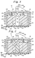
- FIG 5 is a view corresponding to that of Figure 3 and showing a modification of the first embodiment.
- the hollow space formed in the damping material 112 is charged with foam rubber 116 which is generally very light and which may be polyurethane foam rubber.
- the charging of the foam rubber can further contribute toward damping the noise and the vibration produced by the operation of the printing head 10.
- FIG. 6 is a longitudinal cross-section of a wire-dot printing head according to a second embodiment.
- This wire-dot printing head which is generally indicated by reference 72, comprises an annular housing 74 formed of a suitable metal material and having a nose member 76 securely mounted on a front end wall 74a thereof and a printed circuit board 77 securely attached to a rear annular end of the housing 74 through the intermediary of a suitable rubber sheet 78.
- the printing head 72 comprises a ring-like permanent magnet member 80 accommodated in the housing and securely attached to the inner face of the front end wall 74a thereof, an annular block member 82 made of a suitable magnetic material and securely attached to the permanent magnet 80, and twenty four electromagnetic actuator assemblies 84 which are accommodated in an inner chamber defined by the magnet member 80 and the block member 82, and which are annularly arranged along an inner wall surface thereof at regular intervals.
- Each of the electromagnetic actuator assemblies 84 includes a core 86 securely mounted on an inner flange portion 82a extended inward from the annular block member 82, and a solenoid 88 surrounding the core 86 and electrically connected to a multi-connector 90 through a circuit pattern formed on the printed circuit board 77.
- the multi-connector 90 is mounted on the circuit board 77 and has a plurality of connecting pins 92 which are electrically connected to a control circuit board of the printer through a flexible flat cable (not shown).
- the twenty four solenoids 88 can be selectively energized by a driver source circuit provided on the control circuit board of the printer.
- Each of the electromagnetic assemblies 84 further includes an armature 94 supported by a leaf spring 96 projected from the magnet member 80 in a cantilever manner and a beam member or arm 98 securely attached to the armature and extended toward a centre of the housing 74.
- the beam member 98 has a wire element 100 securely attached to an inner or free end thereof and the wire element 98 is extended through and projected out of the nose member 76.
- a through bore 102 is formed in the nose member 76 for the passage of the wire elements 100 and a guide plate 104 and an end wall member 106 are provided in the through bore 102.
- the guide plate 104 may be formed of a suitable metal material and has twenty four small guide holes formed therein through which holes the respective wire elements 100 are passed.
- the end wall member 106 which may be formed of a suitable hard resin material, defines a front face 76a of the nose member 76 and has twenty four small holes formed therein, through which the free ends 100a of the wire elements project out of the front face 76a.
- the corresponding core 86 cooperates with the permanent magnet member 80 and the magnetic block member 82 to form a closed magnetic circuit, and thus the corresponding armature 94 is magnetically adhered to the free end face of the core 86 against a resilient force of the leaf spring 96.
- Electrical energization of the solenoid 88 causes the closed magnetic circuit to be broken, so that the armature 88 is quickly moved from the position at which it is magnetically adhered to the free end face of the core 86, due to the resilient force of the leaf spring.
- the corresponding wire element 100 is driven so as to make a dot.
- the interior of the housing 74 is partially charged with noise/vibration damping material 118 so that the movable elements are not embedded in the charged damping material.
- the damping material 118 is preferably composed of gel-like silicone resin as disclosed in the JUPP '356.
- the charged damping material 118 also features a hollow space 120 formed therein, and thus the increase in the inertial mass of the printing head 72 can be limited due to the formation of the hollow space 120.
- the existence of the hollow space 120 in the damping material 118 contributes toward damping the noise and the vibration produced by the operation of the printing head 72.
- Figure 7 shows a modification of the embodiment shown in Fig. 6.
- the hollow space formed in the damping material 118 is charged with foam rubber 122 which is generally very light, and which may be polyurethane foam rubber. Similar to the embodiment shown in Fig. 5, the charging of the foam rubber can further contribute toward damping the noise and the vibration produced by the operation of the printing head 72.
- the wire elements are driven by actuator means in the form of an array of actuator assemblies arranged around a hollow space, in a concentric fashion in the examples given.
- the hollow space extends through a substantial part of the extent of the damping material in a direction from one side to an opposite side of the damping material, in the examples given from an internal base of the housing, constituted by the rubber sheet 30 or 78, towards the wire elements.
- the examples show a hollow space which terminates in a dome shape short of the upper surface of the gel-like material, which upper surface lies below the substantially horizontally extending arms 58 or 98 and approximately level with the upper ends of the stacks or cores 38 or 86.
- the hollow space is thus bounded on one side by a rubber sheet and on its other sides by the gel-like damping material itself.
Abstract
Description
- The present invention relates to a printing head for a wire-dot printer.
- As is well known, a wire-dot printer is an impact printer. Such printers are in widespread use as office-type printers because the running costs thereof are relatively low. Nevertheless, wire-dot printers are inherently noisy and produce considerable vibration during their operation. This constitutes a factor hindering the spread of the wire-dot printer as a personal-use type.
- Japanese Unexamined Patent Publication (KOKAI) No. 4(1992)-70356 discloses a wire-dot printing head, the interior of which is partially charged with gel-like silicone resin for damping the noise and vibration produced during the operation thereof. The gel-like silicone resin is obtained from silicone oil, by hydrosilylation reaction, and has a cross-link density 1/5 to 1/10 less than that of silicone elastomer. The gel-like silicone resin can exhibit a desired viscoelastic property (elastic coefficient, dissipation factor) to effectively damp the noise and vibration produced by the operation of the printing head. Nevertheless, the inertial mass of the printing head is increased due to the charging of the gel-like silicone resin, to thereby cause an amplification of the lateral shake of a wire-dot printer in which this type of printing head is incorporated, and this lateral shaking of the printer produces another noise. Further, the increase in the inertial mass of the printing head impedes the high-speed printing of the printer, because it is more difficult to quickly accelerate and decelerate the printing head as its inertial mass increases.
- According to the present invention, there is provided a wire-dot printing head comprising a housing and actuator means accommodated in the housing for driving a plurality of wire elements of the printing head, the interior of the housing being partially charged with gel-like damping material for damping noise and vibration produced during operation of the printing head, characterised in that the damping material has a hollow space therein, such that the inertial mass of the printing head is lower due to the presence of the hollow space.
- The damping material may advantageously be composed of gel-like silicone resin. The actuator assemblies may for example be of the piezoelectric type, as exemplified by EP-A-0350258, or of the electromagnetic type, as exemplified by EP-A-0343994.
- In one embodiment, the hollow space is substantially empty. In another embodiment, the hollow space contains foam rubber, for example polyurethane foam rubber.
- Reference will now be made, by way of example, to the accompanying drawings, in which:
- Figure 1 is a perspective view showing a wire-dot printer in which a printing head embodying the present invention can be incorporated;
- Figure 2 is an enlarged perspective view of an assembled printing head of the printer of Figure 1;
- Figure 3 is a longitudinal cross-sectional view of the printing head of Figure 2;
- Figure 4 is an enlarged elevation view showing one of the piezo-actuator assemblies incorporated in the printing head of Figures 2 and 3;
- Figure 5 is a longitudinal cross-sectional view corresponding to that of Figure 3 and showing a modification of the first embodiment;
- Figure 6 is a longitudinal cross-sectional view of a wire-dot printing head of the printer of Figure 1 according to a second embodiment; and
- Figure 7 is a longitudinal cross-sectional view corresponding to that of Figure 6 and showing a modification of the second embodiment.
- Figure 1 shows a representative type of wire-dot printer having a
printing head 10 in which the present invention is embodied. Theprinting head 10 is attached to and supported by acarrier 12 which is slidably mounded on aguide bar 14 extended along aplaten 16. During operation of the printer, thecarrier 12 with theprinting head 10 is moved along theguide bar 14 by a suitable drive mechanism. - Figure 2 shows a perspective, external, view of the
printing head 10 and Figure 3 shows the internal arrangement according to a first embodiment. Theprinting head 10 comprises anannular housing 18, formed of a suitable metal such as steel, and having heat-radiating fins 20 extended outward form an outer side wall thereof and aninner flange 22 extended inward from an inner peripheral edge of a front annular end thereof. Theprinting head 10 also comprises a disk-like plate 24 securely attached to theinner flange 22 of thehousing 18 and having anose member 26 integrally formed thereon, there being a printedcircuit board 28 securely attached to the other or rear annular end of thehousing 18 through the intermediary of asuitable rubber sheet 30. - The
printing head 10 shown comprises twenty four piezo-actuator assemblies 32 accommodated in thehousing 18 and annularly arranged along an inner wall surface thereof at regular intervals. As shown in Fig. 4, each of the piezo-actuator assemblies 32 includes a block member 34 (to be securely attached to theinner flange 22 of the housing through the intermediary of a ring member 36 - Fig. 3) and apiezo stack 38 supported by theblock member 34. In particular, thepiezo stack 38 is composed of a plurality of piezo elements integrally held by atie band 40 the ends of which are securely joined to the respective front and rear ends of thepiezo stack 38. The front end of thepiezo stack 38 is joined to theblock member 34 through the intermediary of atie strip 44 and the rear end thereof is joined to an end of ascrew 44 threaded in aportion 46 extended inward from the rear end of theblock member 34. - A
connector 48 is attached to the extendedportion 46 of theblock member 38 and has a pair of connectingpins 50 which are inserted into the printedcircuit board 28, as shown in Fig. 3, and which are electrically connected to plus and minus electrode terminals of thepiezo stack 38 through a pair ofelectric leads 52. Also, a multi-connector 54 is mounted on thecircuit board 28, as shown in Figs. 2 and 3, and has a plurality of connectingpins 56 which are electrically connected to a control circuit board of the printer through a flexible flat cable (not shown). Of course, the respective connectingpins 56 of themulticonnector 54 are connected to the connecting pins of theconnectors 48 of the twenty four piezo-actuator assemblies through a circuit pattern formed on theboard 28. Thus, the twenty fourpiezo stacks 38 can be selectively energized by a driver source circuit provided on the control circuit board of the printer. - Each of the piezo-
actuator assemblies 32 further includes anarm 58 which is supported by theblock member 34 and thepiezo stack 38 through the intermediary of a pair of parallelleaf spring elements leaf spring element 60a is securely joined to an outer end of thearm 58 and the other end thereof is securely joined to ablock piece 62 fixed to the front end of thepiezo stack 38. Also, one end of theleaf spring element 60b is securely joined to an outer end of thearm 58 and the other end thereof is securely joined to aportion 64 extended inward from the front end of theblock member 34. Thearm 58 has awire element 66 securely attached to an inner or free end thereof, and thewire element 66 is extended through the disk-like plate 24 and thenose member 26 such that afree end 66a of thewire element 66 projects from afront face 26a of thenose member 26, as shown in Fig. 3. When thepiezo stack 38 shown in Fig. 4 is electrically energized, the height or length thereof is increased, so that thearm 58 is rotated in a direction indicated by an arrow A about a middle point of a span length of theleaf spring element 60b. Accordingly, although the increment of the height or length of thepiezo stack 38 is very small, it is amplified by thearm 58 so that thewire element 66 can be driven at a sufficient stroke. - As best shown in Fig. 2, the
free ends 66a of the twenty fourwire elements 66 are arranged in two parallel columns at a given pitch and thefree ends 66a included in one of the two columns are offset by one-half of said pitch with respect to thefree ends 66a included in the other column. Namely, the one-half of the pitch represents a dot pitch at which a printing is carried out by the illustrated printing head. - In the first embodiment, the interior of the
housing 18 is partially charged with gel-like noise/vibration damping material 112 so that the movable elements are not embedded in the charged damping material. Preferably, thedamping material 112 is composed of gel-like silicone resin as disclosed in the JUPP '356. - A
hollow space 114 is formed in thecharged damping material 112; thus the increase in the inertial mass of theprinting head 10 can be limited due to the formation of thehollow space 114. Further, the existence of thehollow space 114 in the dampingmaterial 112 contributes toward damping the noise and the vibration produced by the operation of theprinting head 10. - Figure 5 is a view corresponding to that of Figure 3 and showing a modification of the first embodiment. In this modification, the hollow space formed in the damping
material 112 is charged withfoam rubber 116 which is generally very light and which may be polyurethane foam rubber. The charging of the foam rubber can further contribute toward damping the noise and the vibration produced by the operation of theprinting head 10. - Figure 6 is a longitudinal cross-section of a wire-dot printing head according to a second embodiment. This wire-dot printing head, which is generally indicated by
reference 72, comprises anannular housing 74 formed of a suitable metal material and having anose member 76 securely mounted on afront end wall 74a thereof and a printedcircuit board 77 securely attached to a rear annular end of thehousing 74 through the intermediary of asuitable rubber sheet 78. - The
printing head 72 comprises a ring-likepermanent magnet member 80 accommodated in the housing and securely attached to the inner face of thefront end wall 74a thereof, anannular block member 82 made of a suitable magnetic material and securely attached to thepermanent magnet 80, and twenty fourelectromagnetic actuator assemblies 84 which are accommodated in an inner chamber defined by themagnet member 80 and theblock member 82, and which are annularly arranged along an inner wall surface thereof at regular intervals. Each of theelectromagnetic actuator assemblies 84 includes acore 86 securely mounted on an inner flange portion 82a extended inward from theannular block member 82, and asolenoid 88 surrounding thecore 86 and electrically connected to a multi-connector 90 through a circuit pattern formed on the printedcircuit board 77. The multi-connector 90 is mounted on thecircuit board 77 and has a plurality of connectingpins 92 which are electrically connected to a control circuit board of the printer through a flexible flat cable (not shown). Thus, the twenty foursolenoids 88 can be selectively energized by a driver source circuit provided on the control circuit board of the printer. - Each of the
electromagnetic assemblies 84 further includes anarmature 94 supported by aleaf spring 96 projected from themagnet member 80 in a cantilever manner and a beam member orarm 98 securely attached to the armature and extended toward a centre of thehousing 74. Thebeam member 98 has awire element 100 securely attached to an inner or free end thereof and thewire element 98 is extended through and projected out of thenose member 76. In particular, athrough bore 102 is formed in thenose member 76 for the passage of thewire elements 100 and aguide plate 104 and anend wall member 106 are provided in thethrough bore 102. Theguide plate 104 may be formed of a suitable metal material and has twenty four small guide holes formed therein through which holes therespective wire elements 100 are passed. Theend wall member 106, which may be formed of a suitable hard resin material, defines afront face 76a of thenose member 76 and has twenty four small holes formed therein, through which thefree ends 100a of the wire elements project out of thefront face 76a. - When each of the
solenoids 88 is not electrically energized, thecorresponding core 86 cooperates with thepermanent magnet member 80 and themagnetic block member 82 to form a closed magnetic circuit, and thus thecorresponding armature 94 is magnetically adhered to the free end face of thecore 86 against a resilient force of theleaf spring 96. Electrical energization of thesolenoid 88 causes the closed magnetic circuit to be broken, so that thearmature 88 is quickly moved from the position at which it is magnetically adhered to the free end face of thecore 86, due to the resilient force of the leaf spring. Thus, thecorresponding wire element 100 is driven so as to make a dot. - In this second embodiment, the interior of the
housing 74 is partially charged with noise/vibration damping material 118 so that the movable elements are not embedded in the charged damping material. The dampingmaterial 118 is preferably composed of gel-like silicone resin as disclosed in the JUPP '356. The charged dampingmaterial 118 also features ahollow space 120 formed therein, and thus the increase in the inertial mass of theprinting head 72 can be limited due to the formation of thehollow space 120. Of course, the existence of thehollow space 120 in the dampingmaterial 118 contributes toward damping the noise and the vibration produced by the operation of theprinting head 72. - Figure 7 shows a modification of the embodiment shown in Fig. 6. In this modification, the hollow space formed in the damping
material 118 is charged with foam rubber 122 which is generally very light, and which may be polyurethane foam rubber. Similar to the embodiment shown in Fig. 5, the charging of the foam rubber can further contribute toward damping the noise and the vibration produced by the operation of theprinting head 72. - As can be appreciated from the first and second embodiments and their modifications as shown in Figures 3, 5, 6 and 7, the wire elements are driven by actuator means in the form of an array of actuator assemblies arranged around a hollow space, in a concentric fashion in the examples given. The hollow space extends through a substantial part of the extent of the damping material in a direction from one side to an opposite side of the damping material, in the examples given from an internal base of the housing, constituted by the
rubber sheet arms cores - From all the above, it will thus be understood that the empty or filled hollow space in the gel-like damping material results in a substantial reduction in the inertial mass presented to the actuator assemblies in operation by reducing the amount of gel-like damping material which they resiliently act against as they are driven.
- Finally, it will be understood by those skilled in the art that the foregoing description is of preferred embodiments of the present invention, and that various changes and modifications can be made thereto.
Claims (11)
- A wire-dot printing head comprising a housing (18) and actuator means (38, 88) accommodated in the housing for driving a plurality of wire elements (66) of the printing head, the interior of the housing (18) being partially charged with gel-like damping material for damping noise and vibration produced during operation of the printing head, characterised in that the damping material has a hollow space (114) therein, such that the inertial mass of the printing head is lower due to the presence of the hollow space (114).
- A printing head as set forth in claim 1, wherein the damping material is composed of gel-like silicone resin.
- A printing head as set forth in claim 1 or 2, wherein the hollow space (114) is substantially empty.
- A printing head as set forth in claim 1 or 2, wherein the hollow space (114) contains foam rubber (116).
- A printing head as set forth in claim 4, wherein said foam rubber comprises polyurethane foam rubber.
- A printing head as set forth in any one of the preceding claims, wherein the actuator means (38, 88) comprises an array of actuator elements arranged around the hollow space (114).
- A printing head as set forth in any one of the preceding claims, wherein the hollow space extends through a substantial part of the extent of the damping material in a direction from one side to an opposite side of the damping material.
- A printing head as set forth in claims 6 and 7 wherein said direction extends generally axially of the array of actuating elements.
- A printing head as set forth in any one of the preceding claims, wherein the hollow space is partially bounded by the damping material.
- A printing head as set forth in any one of the preceding claims, wherein the actuator means comprises piezoelectric type actuator means (38).
- A printing head as set forth in any one of claims 1 to 9, wherein the actuator means comprises electromagnetic type actuator means (86, 88).
Applications Claiming Priority (7)
| Application Number | Priority Date | Filing Date | Title |
|---|---|---|---|
| JP4164468A JP2787637B2 (en) | 1992-06-23 | 1992-06-23 | Print head |
| JP16446892 | 1992-06-23 | ||
| JP164468/92 | 1992-06-23 | ||
| JP16446992A JP2743231B2 (en) | 1992-06-23 | 1992-06-23 | Print head |
| JP16446992 | 1992-06-23 | ||
| JP164469/92 | 1992-06-23 | ||
| EP93304915A EP0576274B1 (en) | 1992-06-23 | 1993-06-23 | Wire-dot printing heads |
Related Parent Applications (2)
| Application Number | Title | Priority Date | Filing Date |
|---|---|---|---|
| EP93304915A Division EP0576274B1 (en) | 1992-06-23 | 1993-06-23 | Wire-dot printing heads |
| EP93304915.7 Division | 1993-06-23 |
Publications (3)
| Publication Number | Publication Date |
|---|---|
| EP0768184A2 true EP0768184A2 (en) | 1997-04-16 |
| EP0768184A3 EP0768184A3 (en) | 1997-05-14 |
| EP0768184B1 EP0768184B1 (en) | 2000-05-24 |
Family
ID=26489548
Family Applications (2)
| Application Number | Title | Priority Date | Filing Date |
|---|---|---|---|
| EP93304915A Expired - Lifetime EP0576274B1 (en) | 1992-06-23 | 1993-06-23 | Wire-dot printing heads |
| EP96120767A Expired - Lifetime EP0768184B1 (en) | 1992-06-23 | 1993-06-23 | Wire-dot printing head |
Family Applications Before (1)
| Application Number | Title | Priority Date | Filing Date |
|---|---|---|---|
| EP93304915A Expired - Lifetime EP0576274B1 (en) | 1992-06-23 | 1993-06-23 | Wire-dot printing heads |
Country Status (3)
| Country | Link |
|---|---|
| US (1) | US5639170A (en) |
| EP (2) | EP0576274B1 (en) |
| DE (2) | DE69313370T2 (en) |
Families Citing this family (1)
| Publication number | Priority date | Publication date | Assignee | Title |
|---|---|---|---|---|
| NL2005690A (en) * | 2009-12-22 | 2011-06-23 | Asml Netherlands Bv | Lithographic apparatus. |
Citations (3)
| Publication number | Priority date | Publication date | Assignee | Title |
|---|---|---|---|---|
| EP0343994A2 (en) | 1988-05-27 | 1989-11-29 | Tokyo Electric Co., Ltd. | Dot print head |
| EP0350258A2 (en) | 1988-07-08 | 1990-01-10 | Fujitsu Limited | Dot matrix printing heads |
| JPH0470356A (en) | 1990-07-02 | 1992-03-05 | Fujitsu Ltd | Piezoelectric element-type printing head |
Family Cites Families (13)
| Publication number | Priority date | Publication date | Assignee | Title |
|---|---|---|---|---|
| BE790981A (en) * | 1971-11-04 | 1973-05-07 | Centronics Data Computer | ELASTIC GUIDED PRINTING HEAD |
| US4661002A (en) * | 1983-08-19 | 1987-04-28 | Canon Kabushiki Kaisha | Dot matrix printer |
| JPS60178078A (en) * | 1984-02-27 | 1985-09-12 | Nec Corp | Printer |
| JPS62256160A (en) * | 1986-04-30 | 1987-11-07 | Fujitsu Ltd | Simultaneous access preventing system for interprocessor register |
| JPS63281858A (en) * | 1987-05-15 | 1988-11-18 | Hitachi Ltd | Wire dot printer |
| JPH01190461A (en) * | 1988-01-26 | 1989-07-31 | Seiko Epson Corp | Impact dot head |
| JPH01267049A (en) * | 1988-04-19 | 1989-10-24 | Nec Corp | Printing head assembly |
| JPH0231744U (en) * | 1988-08-23 | 1990-02-28 | ||
| JPH0313348A (en) * | 1989-06-12 | 1991-01-22 | Nec Corp | Printing head cover |
| JPH03288660A (en) * | 1990-04-05 | 1991-12-18 | Seiko Epson Corp | Impact dot head |
| JP2644919B2 (en) * | 1990-11-30 | 1997-08-25 | 富士通株式会社 | Print head |
| JPH04214364A (en) * | 1990-12-10 | 1992-08-05 | Nec Corp | Wire dot-type printing head |
| JP2887908B2 (en) * | 1991-01-16 | 1999-05-10 | 富士通株式会社 | Piezoelectric element print head |
-
1993
- 1993-06-23 DE DE69313370T patent/DE69313370T2/en not_active Expired - Fee Related
- 1993-06-23 DE DE69328734T patent/DE69328734T2/en not_active Expired - Fee Related
- 1993-06-23 EP EP93304915A patent/EP0576274B1/en not_active Expired - Lifetime
- 1993-06-23 EP EP96120767A patent/EP0768184B1/en not_active Expired - Lifetime
-
1995
- 1995-05-30 US US08/453,516 patent/US5639170A/en not_active Expired - Fee Related
Patent Citations (3)
| Publication number | Priority date | Publication date | Assignee | Title |
|---|---|---|---|---|
| EP0343994A2 (en) | 1988-05-27 | 1989-11-29 | Tokyo Electric Co., Ltd. | Dot print head |
| EP0350258A2 (en) | 1988-07-08 | 1990-01-10 | Fujitsu Limited | Dot matrix printing heads |
| JPH0470356A (en) | 1990-07-02 | 1992-03-05 | Fujitsu Ltd | Piezoelectric element-type printing head |
Also Published As
| Publication number | Publication date |
|---|---|
| US5639170A (en) | 1997-06-17 |
| DE69328734D1 (en) | 2000-06-29 |
| EP0576274B1 (en) | 1997-08-27 |
| EP0768184A3 (en) | 1997-05-14 |
| EP0768184B1 (en) | 2000-05-24 |
| DE69313370T2 (en) | 1998-01-02 |
| DE69313370D1 (en) | 1997-10-02 |
| DE69328734T2 (en) | 2000-09-07 |
| EP0576274A3 (en) | 1994-06-29 |
| EP0576274A2 (en) | 1993-12-29 |
Similar Documents
| Publication | Publication Date | Title |
|---|---|---|
| EP1872954B1 (en) | Impact printhead | |
| EP0140658B1 (en) | Ink dot printer | |
| EP0768184B1 (en) | Wire-dot printing head | |
| GB2129740A (en) | Wire drive unit for use in a wire dot print head | |
| EP0267716A2 (en) | Print head for use in a wire matrix printer | |
| WO1983003387A1 (en) | Print wire actuating device and method of manufacture thereof | |
| KR0121784B1 (en) | Wire dot print head | |
| JP2788867B2 (en) | Printing actuator | |
| EP0357057B1 (en) | Armature of printing head for use in wire printer | |
| US4484519A (en) | Stylus driving apparatus for printers | |
| US5322379A (en) | Impact dot print head and printer including same | |
| JPH0237559Y2 (en) | ||
| JPS633819Y2 (en) | ||
| US4839621A (en) | Electromagnetic actuator having improved dampening means | |
| JPS6052360A (en) | Dot impact printing head | |
| KR890003917B1 (en) | Printing mechanism | |
| EP0247621A2 (en) | Dot print head | |
| JP2775843B2 (en) | Print head | |
| JPH0467957A (en) | Impact dot print head for printer | |
| JPS5857971A (en) | Printing head for dot printer | |
| KR200151272Y1 (en) | Impact-type dot matrix print head | |
| JPS61217259A (en) | Wire dot head | |
| JPS63153156A (en) | Wire dot head | |
| KR200155122Y1 (en) | Needle assembler of head for dot printer | |
| KR850003345Y1 (en) | Dot impact printer |
Legal Events
| Date | Code | Title | Description |
|---|---|---|---|
| PUAI | Public reference made under article 153(3) epc to a published international application that has entered the european phase |
Free format text: ORIGINAL CODE: 0009012 |
|
| PUAL | Search report despatched |
Free format text: ORIGINAL CODE: 0009013 |
|
| AC | Divisional application: reference to earlier application |
Ref document number: 576274 Country of ref document: EP |
|
| AK | Designated contracting states |
Kind code of ref document: A2 Designated state(s): DE GB |
|
| AK | Designated contracting states |
Kind code of ref document: A3 Designated state(s): DE GB |
|
| 17P | Request for examination filed |
Effective date: 19971028 |
|
| 17Q | First examination report despatched |
Effective date: 19981105 |
|
| GRAG | Despatch of communication of intention to grant |
Free format text: ORIGINAL CODE: EPIDOS AGRA |
|
| GRAG | Despatch of communication of intention to grant |
Free format text: ORIGINAL CODE: EPIDOS AGRA |
|
| GRAH | Despatch of communication of intention to grant a patent |
Free format text: ORIGINAL CODE: EPIDOS IGRA |
|
| GRAH | Despatch of communication of intention to grant a patent |
Free format text: ORIGINAL CODE: EPIDOS IGRA |
|
| GRAA | (expected) grant |
Free format text: ORIGINAL CODE: 0009210 |
|
| AC | Divisional application: reference to earlier application |
Ref document number: 576274 Country of ref document: EP |
|
| AK | Designated contracting states |
Kind code of ref document: B1 Designated state(s): DE GB |
|
| REF | Corresponds to: |
Ref document number: 69328734 Country of ref document: DE Date of ref document: 20000629 |
|
| EN | Fr: translation not filed | ||
| PLBE | No opposition filed within time limit |
Free format text: ORIGINAL CODE: 0009261 |
|
| STAA | Information on the status of an ep patent application or granted ep patent |
Free format text: STATUS: NO OPPOSITION FILED WITHIN TIME LIMIT |
|
| 26N | No opposition filed | ||
| REG | Reference to a national code |
Ref country code: GB Ref legal event code: IF02 |
|
| PGFP | Annual fee paid to national office [announced via postgrant information from national office to epo] |
Ref country code: DE Payment date: 20080626 Year of fee payment: 16 |
|
| PGFP | Annual fee paid to national office [announced via postgrant information from national office to epo] |
Ref country code: GB Payment date: 20080625 Year of fee payment: 16 |
|
| GBPC | Gb: european patent ceased through non-payment of renewal fee |
Effective date: 20090623 |
|
| PG25 | Lapsed in a contracting state [announced via postgrant information from national office to epo] |
Ref country code: GB Free format text: LAPSE BECAUSE OF NON-PAYMENT OF DUE FEES Effective date: 20090623 |
|
| PG25 | Lapsed in a contracting state [announced via postgrant information from national office to epo] |
Ref country code: DE Free format text: LAPSE BECAUSE OF NON-PAYMENT OF DUE FEES Effective date: 20100101 |