EP0767475A2 - Cord switch - Google Patents
Cord switch Download PDFInfo
- Publication number
- EP0767475A2 EP0767475A2 EP96307277A EP96307277A EP0767475A2 EP 0767475 A2 EP0767475 A2 EP 0767475A2 EP 96307277 A EP96307277 A EP 96307277A EP 96307277 A EP96307277 A EP 96307277A EP 0767475 A2 EP0767475 A2 EP 0767475A2
- Authority
- EP
- European Patent Office
- Prior art keywords
- cord
- cord switch
- wall portion
- predetermined wall
- switch
- Prior art date
- Legal status (The legal status is an assumption and is not a legal conclusion. Google has not performed a legal analysis and makes no representation as to the accuracy of the status listed.)
- Granted
Links
Images


Classifications
-
- H—ELECTRICITY
- H01—ELECTRIC ELEMENTS
- H01H—ELECTRIC SWITCHES; RELAYS; SELECTORS; EMERGENCY PROTECTIVE DEVICES
- H01H3/00—Mechanisms for operating contacts
- H01H3/02—Operating parts, i.e. for operating driving mechanism by a mechanical force external to the switch
- H01H3/14—Operating parts, i.e. for operating driving mechanism by a mechanical force external to the switch adapted for operation by a part of the human body other than the hand, e.g. by foot
- H01H3/141—Cushion or mat switches
- H01H3/142—Cushion or mat switches of the elongated strip type
-
- B—PERFORMING OPERATIONS; TRANSPORTING
- B60—VEHICLES IN GENERAL
- B60J—WINDOWS, WINDSCREENS, NON-FIXED ROOFS, DOORS, OR SIMILAR DEVICES FOR VEHICLES; REMOVABLE EXTERNAL PROTECTIVE COVERINGS SPECIALLY ADAPTED FOR VEHICLES
- B60J10/00—Sealing arrangements
-
- E—FIXED CONSTRUCTIONS
- E05—LOCKS; KEYS; WINDOW OR DOOR FITTINGS; SAFES
- E05F—DEVICES FOR MOVING WINGS INTO OPEN OR CLOSED POSITION; CHECKS FOR WINGS; WING FITTINGS NOT OTHERWISE PROVIDED FOR, CONCERNED WITH THE FUNCTIONING OF THE WING
- E05F15/00—Power-operated mechanisms for wings
- E05F15/40—Safety devices, e.g. detection of obstructions or end positions
- E05F15/42—Detection using safety edges
- E05F15/44—Detection using safety edges responsive to changes in electrical conductivity
- E05F15/443—Detection using safety edges responsive to changes in electrical conductivity specially adapted for vehicle windows or roofs
-
- E—FIXED CONSTRUCTIONS
- E05—LOCKS; KEYS; WINDOW OR DOOR FITTINGS; SAFES
- E05Y—INDEXING SCHEME RELATING TO HINGES OR OTHER SUSPENSION DEVICES FOR DOORS, WINDOWS OR WINGS AND DEVICES FOR MOVING WINGS INTO OPEN OR CLOSED POSITION, CHECKS FOR WINGS AND WING FITTINGS NOT OTHERWISE PROVIDED FOR, CONCERNED WITH THE FUNCTIONING OF THE WING
- E05Y2900/00—Application of doors, windows, wings or fittings thereof
- E05Y2900/50—Application of doors, windows, wings or fittings thereof for vehicles
- E05Y2900/53—Application of doors, windows, wings or fittings thereof for vehicles characterised by the type of wing
- E05Y2900/55—Windows
-
- H—ELECTRICITY
- H01—ELECTRIC ELEMENTS
- H01H—ELECTRIC SWITCHES; RELAYS; SELECTORS; EMERGENCY PROTECTIVE DEVICES
- H01H3/00—Mechanisms for operating contacts
- H01H3/02—Operating parts, i.e. for operating driving mechanism by a mechanical force external to the switch
- H01H3/14—Operating parts, i.e. for operating driving mechanism by a mechanical force external to the switch adapted for operation by a part of the human body other than the hand, e.g. by foot
- H01H3/141—Cushion or mat switches
- H01H3/142—Cushion or mat switches of the elongated strip type
- H01H2003/143—Cushion or mat switches of the elongated strip type provisions for avoiding the contact actuation when the elongated strip is bended
Definitions
- a cord switch 60 has a hollow flexible cord member 62 such as a silicone, a rubber or the like in which the cord member 62 is provided with contact lines 64 at an upper wall portion 62A (which corresponds to one of two wall portions of the cord member 62 generally opposed to each other) and at a lower wall portion 62B (which corresponds to the other of the two wall portions), respectively.
- these contact lines 64 are made contact each other.
- the contact lines 64 may be made contact each other when the cord switch 60 is mounted on the window frame.
- the cord switch 72 is structured such that even when a bending force is applied to the cord switch 72, because the distal end portion of the barrier wall 70 abuts on the bridge conductor 68, the bridge conductor 68 and the contact lines 71 are not made contact each other unnecessarily.
- the bridge conductor 68 do not contact these contact lines 71. Further, when the pressing force acts on the barrier wall 70 vertically, the bridge conductor 68 is pressed in parallel to the barrier wall 70 and does contact the contact lines 71. However, if the pressing force acts on the barrier wall 70 from a transverse or diagonal direction, the barrier wall 70 is not deformed but is inclined due to the pressing force, the bridge conductor 68 is pressed diagonally, so that the bridge conductor 68 does not contact any of the contact lines 71.
- a cord switch comprises a flexible hollow cord member which includes a predetermined wall portion and an opposing portion which generally opposes to the predetermined wall portion and has a transverse cross sectional configuration in which a neutral axis of the cord switch is provided at the predetermined wall portion side of the center of the distance between the predetermined wall portion and the opposing portion, a contact portion which is disposed inwardly of the hollow cord member and which extends on a portion of the predetermined wall portion along the longitudinal direction of the hollow cord member, and a contact body which is disposed apart from the contact portion and extends along the longitudinal direction of the hollow cord member, the contact body being disposed inwardly of the hollow cord member and extending from the opposing portion to the portions between the predetermined wall portion and the opposing portion in the hollow cord member as viewed from a transverse cross section of the hollow cord member.
- the cord switch according to the first aspect when the cord switch according to the first aspect is mounted along an inner peripheral portion of a window frame of a vehicle door through the predetermined wall portion of the cord member, a portion of the cord switch which is positioned at the corner portion of the window frame is bent such that a tensile stress is applied to the predetermined wall portion of the cord member and a compression stress is applied to the opposing portion thereof.
- the cord switch is more bendable at the opposing portion of the cord member because the distance between the opposing portion and the neutral axis is longer than that between the neutral axis and the predetermined wall portion, so that the mounting of the cord switch on the corner portion of the window frame or the like of the vehicle can be facilitated.
- the cross sectional configuration of the opposing portion of the cord member before the cord switch is bent can be maintained, and unless the opposing portion of the cord member is pressed inwardly of the cord switch, an unnecessary contact between the contact portion and the contact body can be prevented.
- positioning the neutral axis at the predetermined wall portion side can be accomplished by inclining the side wall portions of the cord member positioned between the predetermined wall portion and the opposing portion so as to approach each other toward the opposing portion.
- the cross sectional configuration of the cord member may have a generally trapezoidal, a generally semi-circular or a generally triangular configuration.
- the predetermined wall portion is a wall portion which corresponds to a bottom side of the trapezoid.
- the predetermined wall portion is a wall portion which corresponds to a chord portion of the semi-circle and the opposing portion of the cord member is a wall portion which corresponds to a substantially center point (i.e., central portion) of an arc of the semi-circle.
- the predetermined wall portion is a wall portion which corresponds to one of the three sides of the triangle and the opposing portion is a wall portion which corresponds to a vertex of the triangle.
- the cord switch 10 is adhered to the weather strip 24.
- the cord switch 10 may be embedded in the weather strip 24.
- a T-shaped projection (i.e., convex) 40 on the upper wall portion 12A of the cord member 12 and providing on the weather strip 24, a recessed portion (i.e., groove) 42 into which the T-shaped projection 40 is press-fitted, the mounting work of the cord switch 12 can be facilitated.
- the cross sectional configuration of a projection is not limited to a T-shaped configuration. Namely, an anchor-shaped (arrow-shaped) projection (i.e., convex) 50 which is shown in Fig.
Abstract
Description
- The present invention relates to a cord switch which is switched over when a cord member of the cord switch is pressed.
- Considering the safety for the user of the vehicle, a window regulator which is driven by a motor to raise and lower a glass of a vehicle door, for example, has been provided in which a cord switch is mounted on a window frame of the vehicle door, and when any obstacle (or foreign object) has been jammed between the cord switch and the glass of the vehicle door, the cord switch is pressed and switched over, so that rotation of the motor is stopped or reversed.
- As shown in Fig. 14, a cord switch 60 has a hollow
flexible cord member 62 such as a silicone, a rubber or the like in which thecord member 62 is provided withcontact lines 64 at anupper wall portion 62A (which corresponds to one of two wall portions of thecord member 62 generally opposed to each other) and at alower wall portion 62B (which corresponds to the other of the two wall portions), respectively. When thecord member 62 is pressed, thesecontact lines 64 are made contact each other. - However, when the cord switch 60 is mounted on the window frame of the vehicle door, it may be bent largely at the corner of the window frame. Therefore, the
contact lines 64 may be made contact each other when the cord switch 60 is mounted on the window frame. - Therefore, in a
cord switch 72 shown in Fig. 15, abridge conductor 68 is disposed at anupper wall portion 66A of acord member 66 and twocontact lines 71 are disposed at alower wall portion 66B of thecord member 66 with abarrier wall 70 being interposed between these contact lines 71 (see JP-A (Japanese Patent Application Laid-Open) No. 5-41282). - The
cord switch 72 is structured such that even when a bending force is applied to thecord switch 72, because the distal end portion of thebarrier wall 70 abuts on thebridge conductor 68, thebridge conductor 68 and thecontact lines 71 are not made contact each other unnecessarily. - However, unless a pressing force which acts on the
cord member 66 is strong enough to deform thebarrier wall 70, thebridge conductor 68 do not contact thesecontact lines 71. Further, when the pressing force acts on thebarrier wall 70 vertically, thebridge conductor 68 is pressed in parallel to thebarrier wall 70 and does contact thecontact lines 71. However, if the pressing force acts on thebarrier wall 70 from a transverse or diagonal direction, thebarrier wall 70 is not deformed but is inclined due to the pressing force, thebridge conductor 68 is pressed diagonally, so that thebridge conductor 68 does not contact any of thecontact lines 71. - In view of the aforementioned facts, it is an object of the present invention to provide a cord switch in which the desired bendability of the cord switch is accomplished, a contact portion and a contact body are not made contact each other even when the cord switch is bent or flexed, the contact portion and the contact body are made contact each other even when a pressing force which acts on the cord switch is relatively small, and the contact portion and the contact body are made contact each other, regardless of the angle at which the cord switch is pressed.
- In accordance with a first aspect of the present invention, a cord switch comprises a flexible hollow cord member which includes a predetermined wall portion and an opposing portion which generally opposes to the predetermined wall portion and has a transverse cross sectional configuration in which a neutral axis of the cord switch is provided at the predetermined wall portion side of the center of the distance between the predetermined wall portion and the opposing portion, a contact portion which is disposed inwardly of the hollow cord member and which extends on a portion of the predetermined wall portion along the longitudinal direction of the hollow cord member, and a contact body which is disposed apart from the contact portion and extends along the longitudinal direction of the hollow cord member, the contact body being disposed inwardly of the hollow cord member and extending from the opposing portion to the portions between the predetermined wall portion and the opposing portion in the hollow cord member as viewed from a transverse cross section of the hollow cord member.
- Namely, the cord switch according to the first aspect of the present invention is characterized in that the cord switch has a cross sectional configuration of the flexible hollow cord member, in which the neutral axis of the cord switch is provided at the predetermined wall portion side of the center of the distance between the predetermined wall portion and the opposing portion which generally opposes to the predetermined wall portion.
- For example, when the cord switch according to the first aspect is mounted along an inner peripheral portion of a window frame of a vehicle door through the predetermined wall portion of the cord member, a portion of the cord switch which is positioned at the corner portion of the window frame is bent such that a tensile stress is applied to the predetermined wall portion of the cord member and a compression stress is applied to the opposing portion thereof. However, the cord switch is more bendable at the opposing portion of the cord member because the distance between the opposing portion and the neutral axis is longer than that between the neutral axis and the predetermined wall portion, so that the mounting of the cord switch on the corner portion of the window frame or the like of the vehicle can be facilitated. Therefore, even at the corner portion of the window frame, the cross sectional configuration of the opposing portion of the cord member before the cord switch is bent can be maintained, and unless the opposing portion of the cord member is pressed inwardly of the cord switch, an unnecessary contact between the contact portion and the contact body can be prevented.
- Further, positioning the neutral axis at the predetermined wall portion side can be accomplished by inclining the side wall portions of the cord member positioned between the predetermined wall portion and the opposing portion so as to approach each other toward the opposing portion. The cross sectional configuration of the cord member may have a generally trapezoidal, a generally semi-circular or a generally triangular configuration. For example, if the cross sectional configuration of the cord member is generally trapezoidal, the predetermined wall portion is a wall portion which corresponds to a bottom side of the trapezoid. If the cross sectional configuration of the cord member is generally semi-circular, the predetermined wall portion is a wall portion which corresponds to a chord portion of the semi-circle and the opposing portion of the cord member is a wall portion which corresponds to a substantially center point (i.e., central portion) of an arc of the semi-circle. Further, if the cross sectional configuration of the cord member is generally triangular, the predetermined wall portion is a wall portion which corresponds to one of the three sides of the triangle and the opposing portion is a wall portion which corresponds to a vertex of the triangle.
- The contact body is disposed so as to cover the contact portion by extending from both of the side wall portions to the opposing portion in the cord member. Therefore, regardless of the angle at which the cord switch according to the first aspect is pressed, the contact body and the contact portion necessarily contact each other, so that very reliable switching-over of the cord switch can be effected in the cord switch.
- In accordance with a second aspect of the present invention, the cord switch according to the first aspect is provided in which at least one of the contact portion and the contact body is made of a conductive rubber or a conductive rubber in which a wire is embedded. For this reason, these contact portion and contact body can be deformed easily in conformity with deformation or bending of the cord switch. As a result, the cord switch itself according to the second aspect of the present invention can be deformed or bent easily.
- In accordance with a third aspect of the present invention, the cord switch according to the first or second aspect is provided in which one of the cord switch and a member to be mounted on which the cord switch is mounted has a projecting portion and the other of the cord switch and the member to be mounted on which the cord switch is mounted has a recessed portion into which the projecting portion is press-fitted. For this reason, the projecting portion is press-fitted into the recessed portion by merely pressing the cord switch. Further, the projecting portion may be a convex line which extends along the longitudinal direction of the one of the cord switch and the member to be mounted on which the cord switch is mounted, while the recessed portion may be a groove which extends along the longitudinal direction of the other of the cord switch and the member to be mounted on which the cord switch is mounted. Moreover, the projecting portion or the recessed portion is provided at the predetermined wall portion.
- In accordance with a fourth aspect of the present invention, the cord switch according to the first or second aspect is mounted by means of adhesion, embedding or press-fitting on a member to be mounted on which the cord switch is mounted along the inner periphery of a window frame for a window glass which can raise and lower. In this case, when any obstacle has been jammed between the glass and the cord switch, the contact body contacts the contact potion and switching-over of the cord switch is conducted. As a result, it is sensed that the glass has struck any obstacle.
- Preferred embodiments of the present invention will now be described hereinbelow by way of example only with reference to the accompanying drawings, in which:
- Fig. 1 is a cross sectional view illustrating a state in which a cord switch according to a first embodiment of the present invention is mounted;
- Fig. 2 is a cross sectional view of the cord switch according to the first embodiment of the present invention;
- Fig. 3 is a cross sectional view illustrating a state in which a pressing force acts on the cord switch from directly beneath the cord switch according to the first embodiment of the present invention;
- Fig. 4 is a cross sectional view illustrating a state in which a pressing force from a directly transverse direction acts on the cord switch according to the first embodiment of the present invention;
- Fig. 5 is a cross sectional view illustrating a state in which a pressing force from a diagonally downward direction acts on the cord switch according to the first embodiment of the present invention;
- Fig. 6 is a side view of a window frame of a door of a vehicle on which the cord switch according to the first embodiment of the present invention is mounted;
- Fig. 7 is a cross sectional view of a cord switch according to a second embodiment of the present invention;
- Fig. 8 is a cross sectional view of a cord switch according to a third embodiment of the present invention;
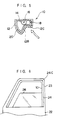
- Fig. 9 is a partially transverse cross sectional view of a modified embodiment illustrating a state in which the cord switch according to the first embodiment of the present invention is mounted on a weather strip;
- Fig. 10 is a partially transverse cross sectional view of another modified embodiment illustrating a state in which the cord switch according to the first embodiment of the present invention is mounted on the weather strip;
- Fig. 11 is a partially transverse cross sectional view of another modified embodiment illustrating a state in which the cord switch according to the first embodiment of the present invention is mounted on the weather strip;
- Fig. 12 is a partially transverse cross sectional view of another modified embodiment illustrating a state in which the cord switch according to the first embodiment of the present invention is mounted on the weather strip;
- Fig. 13 is a partially transverse cross sectional view of another modified embodiment illustrating a state in which the cord switch according to the first embodiment of the present invention is mounted on the weather strip;
- Fig. 14 is a cross sectional view of a conventional cord switch; and
- Fig. 15 is a cross sectional view of a conventional cord switch.
- As shown in Fig. 1, a
cord switch 10 according to a first embodiment of the present invention has a flexiblehollow cord member 12. Thecord member 12 has a trapezoidal cross sectional configuration. In this way, since thecord member 12 has a trapezoidal cross sectional configuration, a neutral axis N of thecord member 12 is positioned at anupper wall portion 12A side of the center of the distance between theupper wall portion 12A and thelower wall portion 12B, so that thecord member 12 is more bendable at thelower wall portion 12B thereof than is at theupper wall portion 12A thereof, and the mounting of thecord member 12 on awindow frame 23 of a vehicle can be facilitated.
Further, even when a tensile force is applied to theupper wall portion 12A and a compression force is applied to thelower wall portion 12B, namely, thecord member 12 is bent such that thelower wall portion 12B is positioned inwardly, a substantially original cross sectional configuration of thecord member 12 is maintained at thelower wall portion 12B thereof, so that an oversensitive contact between theupper wall portion 12A and thelower wall portion 12B is prevented, that is, a malfunction of the cord switch is prevented. In addition, theupper wall portion 12A corresponds to one of the two wall portions which substantially oppose to each other, of thecord member 12. On the other hand, thelower wall portion 12B, that is, the opposing portion described in the above aspects, corresponds to the other of the two wall portions. - On the other hand, at a substantially central portion of the
upper wall portion 12A, aconductive rubber 14 constituting a contact portion is provided to extend along the longitudinal direction of thecord member 12. In this way, when theconductive rubber 14 serving as a contact portion is used, the whole body of thecord switch 10 becomes more bendable than the body of a cord switch in which only metal conductive lines are used. Moreover, theconductive rubber 14 has awire 16 which is embedded at the core portion thereof and decreases the electrical resistance of theconductive rubber 14. - Meanwhile, a
conductive rubber 20 in which awire 18 is embedded is disposed in thecord member 12 so as to extend fromside wall portions 12C of thecord member 12 which are substantially opposed to each other to thelower wall portion 12B in a generally U-shaped configuration. - Next, a description of a state in which the
cord switch 10 according to the present embodiment is mounted on a window frame of a vehicle door will be given in detail hereinafter. - As shown in Fig. 6, a
weather strip 24 is mounted on the generallyrectangular window frame 23 of the vehicle door to be bent along an inner peripheral wall thereof. As shown in Fig. 1, theweather strip 24 has a cross section of a generally L-shaped configuration. Aglass sealing member 26 is attached to astep portion 24A of theweather strip 24. An outer edge of the raiseddoor glass 28 is fitted into theglass sealing member 26 to close the opening of thewindow frame 23. - Further, the
upper wall portion 12A of thecord member 12 is adhered to thelower edge portion 24B of theweather strip 24 and thecord switch 10 is disposed at a position slightly shifted from the moving track of thedoor glass 28. For this reason, even when the door window is closed fully by thewindow glass 28, thecord switch 10 is not pressed by thedoor glass 28 and is not switched over, accordingly. Therefore, it becomes unnecessary to dispose a limit switch or the like for detecting the position of the door glass to determine whether the opening of the door window has been fully closed by thedoor glass 28 or any obstacle has been jammed between the door glass and thewindow frame 23. As a result, a jam preventing mechanism is simplified and the control circuitry for the mechanism can also be simplified. - Further, even when the
cord switch 10 is bent at a corner portion 24C of theweather strip 24, thecord switch 10 is more bendable at thelower wall portion 12B of thecord member 12 than at theupper wall portion 12A thereof, so that thecord switch 10 can substantially maintain the cross sectional configuration thereof before the bending of thecord switch 10. Accordingly, the distance between theconductive rubber 14 and theconductive rubber 20 is maintained substantially constant before and after the bending of thecord switch 10. As a result, an unnecessary contact between theconductive rubber 14 and theconductive rubber 20 can be prevented. - When any obstacle has been jammed, or clamped, between the
door glass 28 and thecord switch 10, thelower wall portion 12B is pressed upwardly, and theconductive rubber 14 and theconductive rubber 20 are made contact each other. Therefore, thecord switch 20 is switched over, for example, from ON to OF switching-over, or from OFF to ON switching-over so as to stop or reverse (i.e., inversely lower the window glass 28) an elevating apparatus (i.e., window regulator) which is not shown. Further, the sensitivity adjustment of thecord switch 10 can be effected easily by changing the thicknesses of the cord member and the conductive rubber, and the distance between the conductive rubbers. - As shown in Fig. 2, regardless of the angle at which the
cord switch 10 is pressed, very reliable switching-over can be effected in thecord switch 10. - As shown in Fig. 3, when a pressing force acts on the
cord switch 10 upwardly, thelower wall portion 12B of thecord member 12 is deformed to protrude upwardly, so that theconductive rubber 14 and theconductive rubber 20 are made contact each other. As shown in Fig. 4, when a pressing force from a directly transverse direction acts on thecord switch 10, one of theside wall portions 12C of thecord member 12 is deformed to make theconductive rubber 14 and theconductive rubber 20 contact each other. Further, as shown in Fig. 5, a pressing force acts on thecord switch 10 diagonally, one of thesidewall portions 12C and thelower wall portion 12B are deformed to make theconductive rubber 14 and theconductive rubber 20 contact each other. - It should be noted that the cross sectional configuration of the
cord member 12 is not limited to a trapezoidal. In order to position a neutral axis of the cord member at the upper wall portion side of the center of the distance between the upper wall portion and the lower wall portion, atriangular cord switch 30 according to a second embodiment of the present invention may be used as shown in Fig. 7 and asemi-circular cord switch 32 according to a third embodiment of the present invention may be used as shown in Fig. 8. - In accordance with the present embodiment, the
cord switch 10 is adhered to theweather strip 24. However, as shown in Fig. 9, thecord switch 10 may be embedded in theweather strip 24. Further, as shown in Fig. 10, by forming a T-shaped projection (i.e., convex) 40 on theupper wall portion 12A of thecord member 12 and providing on theweather strip 24, a recessed portion (i.e., groove) 42 into which the T-shapedprojection 40 is press-fitted, the mounting work of thecord switch 12 can be facilitated. The cross sectional configuration of a projection is not limited to a T-shaped configuration. Namely, an anchor-shaped (arrow-shaped) projection (i.e., convex) 50 which is shown in Fig. 11 or an umbrella-shaped projection (i.e., convex) 52 which is shown in Fig. 12 may be used, alternatively. Further, as shown in Fig. 13, a projecting portion or a convex 56 may be formed on theweather strip 24 and a recessed portion (i.e., groove) 58 into which the projecting portion or the convex 56 is press-fitted may be formed in thecord member 12. - Further, the present embodiment has been applied to a jam preventing apparatus used for the door glass of the vehicle. However, the present invention can be applied to a driverless or radio-controlled vehicle in which the cord switch is mounted on a bumper or the like of the vehicle in order to detect a collision of the vehicle. The present invention can also be applied to prevent any obstacle from being jammed in a so-called sunroof system in which a movable portion of a vehicle roof is automatically opened and closed and in an autodoor system of a 1-box-car type vehicle or the like. Thus, the present invention may be used for a jam preventing application or the like in which a cord switch is provided to be bent adjacent to a movable portion of a vehicle body to prevent any obstacle from being jammed around the movable portion of the vehicle body.
- Since the cord switch according to the present invention has the above-described structure, the cord switch is more bendable than a conventional cord switch. Namely, the contact portion and the contact body are not made contact each other even when the cord switch is bent, they contact each other even when a pressing force which acts on the cord switch is small, and they contact each other regardless of the angle at which the cord switch is pressed.
Claims (10)
- A cord switch, comprising:a flexible hollow cord member which includes a predetermined wall portion, and an opposing portion which generally opposes to said predetermined wall portion, and has a transverse cross sectional configuration in which the neutral axis of said cord switch is provided at the predetermined wall portion side of the center of the distance between said predetermined wall portion and said opposing portion;a contact portion which is disposed inwardly of said hollow cord member and extends on a portion of said predetermined wall portion along the longitudinal direction of said hollow cord member; anda contact body which is disposed apart from said contact portion and extends along the longitudinal direction of said hollow cord member, the contact body being disposed inwardly of said hollow cord member along said opposing portion and the portions between said predetermined wall portion and said opposing portion in said hollow cord member, as viewed from a transverse cross section of said hollow cord member.
- A cord switch according to claim 1, wherein at least one of said contact portion and said contact body is made of a conductive rubber or a conductive rubber in which a wire is embedded.
- A cord switch according to claim 1, wherein one of said cord switch and a member to be mounted on which said cord switch is mounted has a projecting portion and the other of said cord switch and the member to be mounted on which said cord switch is mounted has a recessed portion into which said projecting portion is press-fitted.
- A cord switch according to claim 2, wherein one of said cord switch and a member to be mounted on which said cord switch is mounted has a projecting portion and the other of said cord switch and the member to be mounted on which said cord switch is mounted has a recessed portion into which said projecting portion is press-fitted.
- A cord switch according to claim 1, wherein said cord switch is mounted by means of adhesion, embedding or press-fitting on a member to be mounted which is mounted along the inner periphery of a window frame for a window glass which can raise and lower.
- A cord switch according to claim 2, wherein said cord switch is mounted by means of adhesion, embedding or press-fitting on the member to be mounted which is mounted along the inner periphery of the window frame for the window glass which can raise and lower.
- A cord switch according to claim 1, wherein said cord switch is mounted on the member to be mounted on which said cord switch is mounted via said predetermined wall portion.
- A cord switch according to claim 1, wherein a transverse cross sectional configuration of said cord member is substantially trapezoidal and said predetermined wall portion is a wall portion which corresponds to a bottom side of said substantial trapezoid of said cord member.
- A cord switch according to claim 1, wherein the transverse cross sectional configuration of said cord member is substantially triangular and said predetermined wall portion is a wall portion which corresponds to a side of three sides of said substantial triangle of said cord member.
- A cord switch according to claim 1, wherein the transverse cross sectional configuration of said cord member is substantially semi-circular and said predetermined wall portion is a wall portion which corresponds to a chord of said substantial semi-circle of said cord member.
Applications Claiming Priority (3)
| Application Number | Priority Date | Filing Date | Title |
|---|---|---|---|
| JP7259062A JPH09102239A (en) | 1995-10-05 | 1995-10-05 | Cord switch |
| JP259062/95 | 1995-10-05 | ||
| JP25906295 | 1995-10-05 |
Publications (3)
| Publication Number | Publication Date |
|---|---|
| EP0767475A2 true EP0767475A2 (en) | 1997-04-09 |
| EP0767475A3 EP0767475A3 (en) | 1998-10-21 |
| EP0767475B1 EP0767475B1 (en) | 2004-05-06 |
Family
ID=17328803
Family Applications (1)
| Application Number | Title | Priority Date | Filing Date |
|---|---|---|---|
| EP96307277A Expired - Lifetime EP0767475B1 (en) | 1995-10-05 | 1996-10-04 | Cord switch |
Country Status (5)
| Country | Link |
|---|---|
| US (1) | US5920044A (en) |
| EP (1) | EP0767475B1 (en) |
| JP (1) | JPH09102239A (en) |
| CA (1) | CA2187059C (en) |
| DE (1) | DE69632372T2 (en) |
Cited By (6)
| Publication number | Priority date | Publication date | Assignee | Title |
|---|---|---|---|---|
| EP0935268A2 (en) * | 1998-02-09 | 1999-08-11 | Shinmei Rubber Ind. Co., Ltd. | Omnidirectional response cable switch |
| GB2351656B (en) * | 1998-11-03 | 2001-10-17 | Ulland Islwyn Watkins | A detector arrangement |
| EP1876048A1 (en) * | 2006-07-08 | 2008-01-09 | GUMMI-WELZ GmbH u. Co. KG GUMMI-KUNSTSTOFFTECHNIK-SCHAUMSTOFFE | Finger protection strip, in particular for indoor and outdoor swing doors |
| EP3023279A1 (en) * | 2014-11-21 | 2016-05-25 | Nishikawa Rubber Co., Ltd. | Protector with sensor |
| EP3023280A1 (en) * | 2014-11-21 | 2016-05-25 | Nishikawa Rubber Co., Ltd. | Protector with sensor |
| EP3564978A1 (en) * | 2018-05-03 | 2019-11-06 | Electrolux Appliances Aktiebolag | Ignition switch |
Families Citing this family (10)
| Publication number | Priority date | Publication date | Assignee | Title |
|---|---|---|---|---|
| DE19908385C2 (en) * | 1999-02-26 | 2001-11-15 | Petri Ag | Contact profile for horn release |
| JP2001266701A (en) * | 2000-03-15 | 2001-09-28 | Bridgestone Corp | Pressure-sensitive switch |
| GB0030097D0 (en) * | 2000-12-09 | 2001-01-24 | Meritor Light Vehicle Sys Ltd | Assembly |
| ITBS20010019A1 (en) * | 2001-03-12 | 2002-09-12 | Stagnoli T G S R L | EDGE EDGE PERFECTED FOR UP-AND-OVER SHUTTERS |
| US6437263B1 (en) * | 2001-10-11 | 2002-08-20 | Lester E. Burgess | Drape sensor |
| US20050117270A1 (en) * | 2003-10-20 | 2005-06-02 | Mayser Gmbh & Co. Kg | Profile arrangement for jamming protection and injection mould |
| JP6317144B2 (en) * | 2014-03-18 | 2018-04-25 | 西川ゴム工業株式会社 | Protector with sensor |
| JP6424073B2 (en) * | 2014-11-21 | 2018-11-14 | 西川ゴム工業株式会社 | Protector with sensor |
| JP6424072B2 (en) * | 2014-11-21 | 2018-11-14 | 西川ゴム工業株式会社 | Protector with sensor |
| EP3653824A1 (en) * | 2018-11-15 | 2020-05-20 | Inalfa Roof Systems Group B.V. | Device for detecting an impact force and a method of manufacturing thereof |
Citations (1)
| Publication number | Priority date | Publication date | Assignee | Title |
|---|---|---|---|---|
| EP0654575A1 (en) * | 1993-11-22 | 1995-05-24 | Karlheinz Beckhausen | Safety contact edge with protective coating |
Family Cites Families (9)
| Publication number | Priority date | Publication date | Assignee | Title |
|---|---|---|---|---|
| US3710050A (en) * | 1970-09-14 | 1973-01-09 | A Richards | Electronic pressure sensitive switch |
| EP0104414B1 (en) * | 1982-08-31 | 1987-05-06 | Erwin Sick GmbH Optik-Elektronik | An elongate resilient section at the closure edge of a closure |
| DE3232365C2 (en) * | 1982-08-31 | 1986-07-10 | Erwin Sick Gmbh Optik-Elektronik, 7808 Waldkirch | Elastic profile on the closing edge of a cover |
| DE3427771A1 (en) * | 1984-07-27 | 1986-02-06 | Audi AG, 8070 Ingolstadt | Anti-jam device for vehicles equipped with an electrically actuable window lifter |
| ATE104011T1 (en) * | 1988-08-05 | 1994-04-15 | Karlheinz Beckhausen | SAFETY CONTACT RAIL. |
| DE3921533A1 (en) * | 1989-06-30 | 1991-01-03 | Karlheinz Beckhausen | SAFETY CONTACT RAIL |
| US5259143A (en) * | 1992-04-17 | 1993-11-09 | Wayne-Dalton Corp. | Astragal for closure members |
| US5296658A (en) * | 1992-09-25 | 1994-03-22 | Rockwell International Corporation | Safety edge switch for detection of obstructions encountered by a moving object |
| JPH077035A (en) * | 1993-06-18 | 1995-01-10 | Matsushita Electric Ind Co Ltd | Wire bonder |
-
1995
- 1995-10-05 JP JP7259062A patent/JPH09102239A/en active Pending
-
1996
- 1996-10-01 US US08/724,218 patent/US5920044A/en not_active Expired - Lifetime
- 1996-10-03 CA CA002187059A patent/CA2187059C/en not_active Expired - Fee Related
- 1996-10-04 DE DE69632372T patent/DE69632372T2/en not_active Expired - Lifetime
- 1996-10-04 EP EP96307277A patent/EP0767475B1/en not_active Expired - Lifetime
Patent Citations (1)
| Publication number | Priority date | Publication date | Assignee | Title |
|---|---|---|---|---|
| EP0654575A1 (en) * | 1993-11-22 | 1995-05-24 | Karlheinz Beckhausen | Safety contact edge with protective coating |
Cited By (10)
| Publication number | Priority date | Publication date | Assignee | Title |
|---|---|---|---|---|
| EP0935268A2 (en) * | 1998-02-09 | 1999-08-11 | Shinmei Rubber Ind. Co., Ltd. | Omnidirectional response cable switch |
| EP0935268A3 (en) * | 1998-02-09 | 2000-09-06 | Shinmei Rubber Ind. Co., Ltd. | Omnidirectional response cable switch |
| GB2351656B (en) * | 1998-11-03 | 2001-10-17 | Ulland Islwyn Watkins | A detector arrangement |
| EP1876048A1 (en) * | 2006-07-08 | 2008-01-09 | GUMMI-WELZ GmbH u. Co. KG GUMMI-KUNSTSTOFFTECHNIK-SCHAUMSTOFFE | Finger protection strip, in particular for indoor and outdoor swing doors |
| EP3023279A1 (en) * | 2014-11-21 | 2016-05-25 | Nishikawa Rubber Co., Ltd. | Protector with sensor |
| EP3023280A1 (en) * | 2014-11-21 | 2016-05-25 | Nishikawa Rubber Co., Ltd. | Protector with sensor |
| US9759003B2 (en) | 2014-11-21 | 2017-09-12 | Nishikawa Rubber Co., Ltd. | Protector with sensor |
| US9758108B2 (en) | 2014-11-21 | 2017-09-12 | Nishikawa Rubber Co., Ltd. | Protector with sensor |
| EP3564978A1 (en) * | 2018-05-03 | 2019-11-06 | Electrolux Appliances Aktiebolag | Ignition switch |
| WO2019211126A1 (en) * | 2018-05-03 | 2019-11-07 | Electrolux Appliances Aktiebolag | Ignition switch |
Also Published As
| Publication number | Publication date |
|---|---|
| EP0767475A3 (en) | 1998-10-21 |
| EP0767475B1 (en) | 2004-05-06 |
| JPH09102239A (en) | 1997-04-15 |
| DE69632372T2 (en) | 2004-09-09 |
| CA2187059A1 (en) | 1997-04-06 |
| US5920044A (en) | 1999-07-06 |
| CA2187059C (en) | 2004-06-22 |
| DE69632372D1 (en) | 2004-06-09 |
Similar Documents
| Publication | Publication Date | Title |
|---|---|---|
| EP0767475B1 (en) | Cord switch | |
| CA2182649C (en) | Cord switch | |
| CA2203431C (en) | Side visor having pinching sensing member and power window apparatus using the same | |
| US6340199B1 (en) | Electricity feeding device for vehicular slide doors | |
| US6955079B2 (en) | Foreign material detector for sliding door and detecting method thereof | |
| EP0666956B1 (en) | Safety edge switch for detection of obstructions encountered by a moving object | |
| US5932931A (en) | Vehicle window control system responsive to external force | |
| US10745959B2 (en) | Touch sensor unit | |
| EP0782158A2 (en) | Pressure-sensitive cable switch | |
| US6290283B1 (en) | Drive device for vehicular slide doors | |
| CN1086839C (en) | Force-responsive detectors and systems | |
| JPH11278049A (en) | Obstacle detecting system for automatic lifting device of pane of automobile | |
| US20020117983A1 (en) | Electrically moving apparatus for moving a movable member | |
| US20030074840A1 (en) | Vehicular power window safety device | |
| JP3784969B2 (en) | Pressure detection device | |
| JP3853958B2 (en) | Pinch detection device | |
| JPH09288931A (en) | Cord switch | |
| JP3334477B2 (en) | Powered window opener | |
| JP2006150993A (en) | Weather strip for automobile | |
| JPH10100677A (en) | Seal structure of door window glass used for automobile | |
| JPH1116441A (en) | Attaching structure of pressure sensor | |
| JPH1136701A (en) | Foreign mater detecting element for window of automobile | |
| JPH09180580A (en) | Cord switch | |
| KR100439909B1 (en) | Device for detecting an obstruction for an electric regulator of a door windows in a motor vehicle | |
| US7605553B2 (en) | System for safely opening/closing power window of vehicle |
Legal Events
| Date | Code | Title | Description |
|---|---|---|---|
| PUAI | Public reference made under article 153(3) epc to a published international application that has entered the european phase |
Free format text: ORIGINAL CODE: 0009012 |
|
| AK | Designated contracting states |
Kind code of ref document: A2 Designated state(s): CH DE FR GB IT LI SE |
|
| RAP1 | Party data changed (applicant data changed or rights of an application transferred) |
Owner name: ASMO CO. LTD. Owner name: BRIDGESTONE CORPORATION |
|
| PUAL | Search report despatched |
Free format text: ORIGINAL CODE: 0009013 |
|
| AK | Designated contracting states |
Kind code of ref document: A3 Designated state(s): CH DE FR GB IT LI SE |
|
| 17P | Request for examination filed |
Effective date: 19990206 |
|
| 17Q | First examination report despatched |
Effective date: 20030225 |
|
| GRAP | Despatch of communication of intention to grant a patent |
Free format text: ORIGINAL CODE: EPIDOSNIGR1 |
|
| GRAS | Grant fee paid |
Free format text: ORIGINAL CODE: EPIDOSNIGR3 |
|
| GRAA | (expected) grant |
Free format text: ORIGINAL CODE: 0009210 |
|
| RAP1 | Party data changed (applicant data changed or rights of an application transferred) |
Owner name: ASMO CO. LTD. |
|
| AK | Designated contracting states |
Kind code of ref document: B1 Designated state(s): CH DE FR GB IT LI SE |
|
| PG25 | Lapsed in a contracting state [announced via postgrant information from national office to epo] |
Ref country code: LI Free format text: LAPSE BECAUSE OF FAILURE TO SUBMIT A TRANSLATION OF THE DESCRIPTION OR TO PAY THE FEE WITHIN THE PRESCRIBED TIME-LIMIT Effective date: 20040506 Ref country code: IT Free format text: LAPSE BECAUSE OF FAILURE TO SUBMIT A TRANSLATION OF THE DESCRIPTION OR TO PAY THE FEE WITHIN THE PRE;WARNING: LAPSES OF ITALIAN PATENTS WITH EFFECTIVE DATE BEFORE 2007 MAY HAVE OCCURRED AT ANY TIME BEFORE 2007. THE CORRECT EFFECTIVE DATE MAY BE DIFFERENT FROM THE ONE RECORDED.SCRIBED TIME-LIMIT Effective date: 20040506 Ref country code: CH Free format text: LAPSE BECAUSE OF FAILURE TO SUBMIT A TRANSLATION OF THE DESCRIPTION OR TO PAY THE FEE WITHIN THE PRESCRIBED TIME-LIMIT Effective date: 20040506 |
|
| REG | Reference to a national code |
Ref country code: GB Ref legal event code: FG4D |
|
| REG | Reference to a national code |
Ref country code: CH Ref legal event code: EP |
|
| REF | Corresponds to: |
Ref document number: 69632372 Country of ref document: DE Date of ref document: 20040609 Kind code of ref document: P |
|
| PG25 | Lapsed in a contracting state [announced via postgrant information from national office to epo] |
Ref country code: SE Free format text: LAPSE BECAUSE OF FAILURE TO SUBMIT A TRANSLATION OF THE DESCRIPTION OR TO PAY THE FEE WITHIN THE PRESCRIBED TIME-LIMIT Effective date: 20040806 |
|
| REG | Reference to a national code |
Ref country code: CH Ref legal event code: PL |
|
| ET | Fr: translation filed | ||
| PLBE | No opposition filed within time limit |
Free format text: ORIGINAL CODE: 0009261 |
|
| STAA | Information on the status of an ep patent application or granted ep patent |
Free format text: STATUS: NO OPPOSITION FILED WITHIN TIME LIMIT |
|
| 26N | No opposition filed |
Effective date: 20050208 |
|
| PGFP | Annual fee paid to national office [announced via postgrant information from national office to epo] |
Ref country code: DE Payment date: 20100929 Year of fee payment: 15 |
|
| PGFP | Annual fee paid to national office [announced via postgrant information from national office to epo] |
Ref country code: GB Payment date: 20110928 Year of fee payment: 16 |
|
| PGFP | Annual fee paid to national office [announced via postgrant information from national office to epo] |
Ref country code: FR Payment date: 20111103 Year of fee payment: 16 |
|
| GBPC | Gb: european patent ceased through non-payment of renewal fee |
Effective date: 20121004 |
|
| REG | Reference to a national code |
Ref country code: FR Ref legal event code: ST Effective date: 20130628 |
|
| PG25 | Lapsed in a contracting state [announced via postgrant information from national office to epo] |
Ref country code: DE Free format text: LAPSE BECAUSE OF NON-PAYMENT OF DUE FEES Effective date: 20130501 Ref country code: GB Free format text: LAPSE BECAUSE OF NON-PAYMENT OF DUE FEES Effective date: 20121004 |
|
| REG | Reference to a national code |
Ref country code: DE Ref legal event code: R119 Ref document number: 69632372 Country of ref document: DE Effective date: 20130501 |
|
| PG25 | Lapsed in a contracting state [announced via postgrant information from national office to epo] |
Ref country code: FR Free format text: LAPSE BECAUSE OF NON-PAYMENT OF DUE FEES Effective date: 20121031 |