EP0767346A2 - Brennstoffbefeuerter Brenner - Google Patents
Brennstoffbefeuerter Brenner Download PDFInfo
- Publication number
- EP0767346A2 EP0767346A2 EP96307255A EP96307255A EP0767346A2 EP 0767346 A2 EP0767346 A2 EP 0767346A2 EP 96307255 A EP96307255 A EP 96307255A EP 96307255 A EP96307255 A EP 96307255A EP 0767346 A2 EP0767346 A2 EP 0767346A2
- Authority
- EP
- European Patent Office
- Prior art keywords
- burner
- port
- flame
- fuel
- ports
- Prior art date
- Legal status (The legal status is an assumption and is not a legal conclusion. Google has not performed a legal analysis and makes no representation as to the accuracy of the status listed.)
- Ceased
Links
Images


Classifications
-
- F—MECHANICAL ENGINEERING; LIGHTING; HEATING; WEAPONS; BLASTING
- F24—HEATING; RANGES; VENTILATING
- F24C—DOMESTIC STOVES OR RANGES ; DETAILS OF DOMESTIC STOVES OR RANGES, OF GENERAL APPLICATION
- F24C3/00—Stoves or ranges for gaseous fuels
- F24C3/002—Stoves
- F24C3/006—Stoves simulating flames
Definitions
- the present invention relates to fuel-fired burners and, more particularly, to so-called solid fuel effect fires, such as coal or log effect gas fires, incorporating such burners.
- Some known solid fuel effect space heating fires are available with imitation flame effects. Such effects may be operated by electricity.
- a flicker intended to imitate the flames of a real coal or log fire may be produced by spinners mounted on pivots over light bulbs and rotated by a current of warm air rising from a burner below. The flickering light is seen by an observer through imitation solid fuel and/or as reflected light from a wall of surface behind the imitation solid fuel.
- these decorative effect flames are generally constant, i.e. they do not change substantially in appearance over a period of time during which the fire is in use.
- An object of this invention is to provide a burner which produces a more dynamic or realistic decorative live flame effect.
- the invention provides a fuel fired burner for use in a solid fuel effect fire, the burner having at least one burner port for supporting a decorative effect flame, in which the port is connected to a power driven means which, when the burner is in use, is operable so as to vary automatically and continually the aeration of the fuel/air mixture which emerges from the burner port such that the flame supported by the burner port is of continually changing visual appearance.
- the burner may have two or more such decorative flame effect burner ports.
- the aerating varying means may be arranged to vary the aeration to both or all of the ports in such a manner that for the majority of the time the means is operating the appearance of the flame at any one port is different to the appearance of the flame at the other port or at least at one of the other ports.
- the means may vary the aeration at the or each port in a substantially cyclical manner.
- the means may be arranged so as to vary the primary aeration at the or each port such that the flame supported therefrom varies between being a blue flame and a yellow flame.
- the decorative effect varying means of the burner may be arranged so as to vary the primary aeration at the or each port such that the flame, during the stage when it is yellow, momentarily becomes detached from the port.
- the power driven means may comprise a movable member having one or more openings in communication with a source of oxygen, for example ambient or surrounding air, and a stationary member having one or more holes to which the port is, or respective ones of the ports are, connected by conduit means for conveying air (as pre-aeration air) towards the port or ports.
- the movable member is movable in a substantially repetitive manner and such that at various times and to different extent the or each opening overlaps with the or one of the apertures thereby placing the, or the associated, burner port in communication with the source of air.
- the appearance of the flame(s) at the port(s) also changes.
- the movable member may have different sized openings whilst the stationary member may have substantially equi-sized holes.
- the movable member may be a rotatable member, in which case one of the rotatable member and stationary member may be located inside the other member, the rotatable member being provided with the or each opening, and the stationary member being provided with the or each hole.
- the rotatable member may be generally cylindrical and be mounted in a complimentary cylindrical recess provided in the stationary member, with the cylindrical wall of the rotatable member being provided with the or each opening and the corresponding wall of the stationary member being provided with the or each hole.
- the rotatable means is provided with a spindle via which rotary movement is transferred to the rotatable member.
- the invention provides a solid fuel effect fire, such as a fuel-gas space heating fire, incorporating a burner according to the first aspect of this invention.
- the burner 1 comprises a power drivable means 2 for varying automatically and continually the pre-aeration of the fuel gas/air mixture supplied to burner ports 3.
- the means 2 comprises a first movable part 5 of generally cylindrical form and a second stationary part 7 in the form of a generally square block having a complimentary cylindrical recess 9 in which the cylindrical part 5 is mounted and is rotatable.
- the cylindrical part 5 comprises a circular base 11 and a cylindrical wall 13 extending upwardly from the periphery of the base and having cut-out openings 15a, 15b, 15c, 15d and 15e between cylindrical wall segments 13a.
- Each side wall 17 of the block 7 is provided with a through hole 19 with each such hole providing communication between the recess and the outside of the block.
- Respective pipes 21 are fitted at one end into the holes 19 and at the other end are connected to a branch portion 23a of a tube 23 extending from fuel gas nozzles 25 to respective burner ports.
- Fuel gas supply pipes or lines are connected to the gas nozzles 25 as indicated by chain lines 27 when the burner is installed and ready for use in, for example, a coal effect fire.
- a drive spindle 31 is located in a recess 32 in a hub-like portion 33 at the centre of the rotatable part 5.
- the spindle 31 extends through an aperture 35 in the base of the block 7.
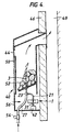
- the spindle 31 When the burner 1 is mounted in a gas fire 40 the spindle 31 is connected to a rotary drive means such as an electric motor as shown at 42 in Figure 4.
- a rotary drive means such as an electric motor as shown at 42 in Figure 4.
- the stationary part 2 and the rotatable part 5 may be made, for example, of plastics material.
- the two parts are, of course, so arranged and constructed that the rotatable part is readily rotatable in the stationary block.
- FIGS 3 and 4 show, schematically, a solid fuel effect space heating gas fire 40.
- the fire comprises a housing 44 mounted on a wall 46 such that gaseous products of combustion pass to the chimney 48.
- the housing has a transparent panel 50 in its front. As viewed through the panel 50 there is supported in the housing 44 an arrangement or pile of ceramic logs or coals 52 to simulate the appearance of an actual log or coal fire.
- the housing 44 also houses the burner 1 described in Figures 1 and 2. For sake of simplicity, just one of the three burner ports 3 is shown in Figures 3 and 4.
- the port 3 is positioned within the ceramic logs or coals preferably so as not to be visible when the logs or coals are viewed through the glass panel.
- the tube 27 is connected to a supply of fuel gas via on/off control valve 54, and the spindle 31 is connected to small electric motor 42.
- An apertured cover 56 is fitted over the open top of the rotary part and this enables the hole 19 in the stationary to communicate with ambient air which enters the housing 44 via a grill 56 in the lower front part of the housing.
- the gas supply to the burner ports 3 is turned on, the electric motor 42 is switched on, and the gas emerging from ports is ignited by energising ignition means (not shown).
- the hole 19 is fully closed, or partially or fully open to the ambient air, depending on the position of the openings 15a, 15b, 15c, 15d and 15e and wall segments 13a as they pass directly in front of the hole 19.
- Each of the openings is of different width and each of the wall segments is of different width such that the flame appearing at the port 3 constantly changes in accordance with the pattern of the alternating openings and wall segments for each rotation of the rotary part.
- the arrangement is so designed that a plurality of dynamic flames that continually grow and shrink in size and are out of phase with each other is produced.
- the rotatable part may be different.
- the electric motor may be omitted and the spindle depending from the rotatable part may carry a vane device which, in response to an upward draught from below of channelled warm air from, for example, the main burner, rotates to cause the spindle and thus the rotatable part to rotate.
- the stationary part may comprise an apertured flat disc with the pipes 21 connected to the apertures
- the rotary part may comprise a flat disc which is also apertured or provided with gaps through its thickness.
Landscapes
- Engineering & Computer Science (AREA)
- Chemical & Material Sciences (AREA)
- Combustion & Propulsion (AREA)
- Mechanical Engineering (AREA)
- General Engineering & Computer Science (AREA)
- Gas Burners (AREA)
- Combustion Of Fluid Fuel (AREA)
Applications Claiming Priority (2)
| Application Number | Priority Date | Filing Date | Title |
|---|---|---|---|
| GB9520450 | 1995-10-06 | ||
| GB9520450A GB2306001B (en) | 1995-10-06 | 1995-10-06 | Fuel-fired burners |
Publications (2)
| Publication Number | Publication Date |
|---|---|
| EP0767346A2 true EP0767346A2 (de) | 1997-04-09 |
| EP0767346A3 EP0767346A3 (de) | 1999-03-24 |
Family
ID=10781894
Family Applications (1)
| Application Number | Title | Priority Date | Filing Date |
|---|---|---|---|
| EP96307255A Ceased EP0767346A3 (de) | 1995-10-06 | 1996-10-04 | Brennstoffbefeuerter Brenner |
Country Status (4)
| Country | Link |
|---|---|
| US (1) | US5795144A (de) |
| EP (1) | EP0767346A3 (de) |
| AU (1) | AU695286B2 (de) |
| GB (1) | GB2306001B (de) |
Cited By (1)
| Publication number | Priority date | Publication date | Assignee | Title |
|---|---|---|---|---|
| EP1632717A3 (de) * | 2004-09-04 | 2006-04-12 | Schott AG | Flächiger atmosphärischer Gasbrenner |
Families Citing this family (5)
| Publication number | Priority date | Publication date | Assignee | Title |
|---|---|---|---|---|
| US5938421A (en) * | 1997-11-12 | 1999-08-17 | Gas Research Institute | Flame movement method and system |
| US5934269A (en) * | 1998-03-27 | 1999-08-10 | Tru-Flex Metal Hose Corporation | Flexible fuel tube assembly for gas-fired appliance and installation method |
| GB2345956A (en) * | 1999-01-21 | 2000-07-26 | Windsor & Sons Ltd B | Artificial coal log gas fire |
| EP1039229A3 (de) | 1999-03-23 | 2002-04-17 | Concentric Controls Limited | Gasgreät |
| GB2381309B (en) * | 2001-10-05 | 2005-06-15 | Valor Ltd | Heating appliance |
Family Cites Families (9)
| Publication number | Priority date | Publication date | Assignee | Title |
|---|---|---|---|---|
| US816154A (en) * | 1904-04-04 | 1906-03-27 | Fortunato Marciano D Arsi | Illuminated display apparatus. |
| US830092A (en) * | 1905-02-08 | 1906-09-04 | Charles Matthews Jr | Device for intermittent gas-lights. |
| GB1455558A (en) * | 1972-10-30 | 1976-11-17 | Wsa Eng Co Ltd | Gas burners |
| DE3276834D1 (en) * | 1982-05-07 | 1987-08-27 | Mer Joseph Le | Programme apparatus with a combustion-air damper for operating boiler burners |
| GB2168472A (en) * | 1984-12-13 | 1986-06-18 | Frederich Hans Rathgeber | Heating appliance control system |
| US4728284A (en) * | 1987-02-12 | 1988-03-01 | Maxon Corporation | Adjustable combustion rate air/fuel proportioned burner assembly |
| GB2208703A (en) * | 1987-08-14 | 1989-04-12 | Grate Glow Fires | Fuel effect gas fires |
| GB8910607D0 (en) * | 1989-05-09 | 1989-06-21 | Turnright Controls | Gas fuelled appliances |
| GB2280023B (en) * | 1993-07-09 | 1997-01-08 | British Gas Plc | Apparatus for detecting the effective ratio of air to fuel gas in a combustible mixture |
-
1995
- 1995-10-06 GB GB9520450A patent/GB2306001B/en not_active Expired - Fee Related
-
1996
- 1996-10-04 EP EP96307255A patent/EP0767346A3/de not_active Ceased
- 1996-10-07 US US08/726,931 patent/US5795144A/en not_active Expired - Fee Related
- 1996-10-08 AU AU68071/96A patent/AU695286B2/en not_active Ceased
Non-Patent Citations (1)
| Title |
|---|
| None |
Cited By (1)
| Publication number | Priority date | Publication date | Assignee | Title |
|---|---|---|---|---|
| EP1632717A3 (de) * | 2004-09-04 | 2006-04-12 | Schott AG | Flächiger atmosphärischer Gasbrenner |
Also Published As
| Publication number | Publication date |
|---|---|
| GB2306001B (en) | 1999-09-08 |
| EP0767346A3 (de) | 1999-03-24 |
| AU6807196A (en) | 1997-04-10 |
| GB9520450D0 (en) | 1995-12-06 |
| US5795144A (en) | 1998-08-18 |
| AU695286B2 (en) | 1998-08-13 |
| GB2306001A (en) | 1997-04-23 |
Similar Documents
| Publication | Publication Date | Title |
|---|---|---|
| EP1020685B1 (de) | Elektrischer Kaminofen | |
| US5452709A (en) | Tiered-logs gas-burning heaters or fireplace insert | |
| CN1461398B (zh) | 火焰模拟装置 | |
| GB2151772A (en) | Domestic heating appliance | |
| GB2152655A (en) | Gas fire with coal effect | |
| US3760790A (en) | Gas fireplace unit | |
| CA2022678A1 (en) | Method and apparatus for burning gas in the combustion chamber of a fireplace | |
| NZ231644A (en) | Gas fired artificial log fireplace assembly | |
| US4602609A (en) | Gas fire appliances | |
| US5795144A (en) | Fuel-fired burners | |
| US6250913B1 (en) | Burner | |
| GB2182431A (en) | Gas fire | |
| EP0926445B1 (de) | Gasbrenner für Kamin | |
| GB2072832A (en) | Gas fires | |
| US7160103B2 (en) | Method and apparatus for modifying the path of a flame | |
| CA1239945A (en) | Flicker flame fire | |
| GB2169700A (en) | Simulated solid-fuel gas fires | |
| GB2350420A (en) | Gas fired heating appliance with a simulated flame effect | |
| GB2147995A (en) | Simulated solid fuel gas fires | |
| JPH068403Y2 (ja) | 薪型暖房機 | |
| EP0400845B1 (de) | Gasbrenner | |
| EP0700500A1 (de) | Ölbefeuerter brenner | |
| GB2221026A (en) | Gas burner | |
| CA2255305C (en) | Gas burner for fireplace | |
| GB2156068A (en) | Solid fuel effect gas fires |
Legal Events
| Date | Code | Title | Description |
|---|---|---|---|
| PUAI | Public reference made under article 153(3) epc to a published international application that has entered the european phase |
Free format text: ORIGINAL CODE: 0009012 |
|
| 17P | Request for examination filed |
Effective date: 19961104 |
|
| AK | Designated contracting states |
Kind code of ref document: A2 Designated state(s): BE DE ES FR GB IT NL SE |
|
| RAP1 | Party data changed (applicant data changed or rights of an application transferred) |
Owner name: BG PUBLIC LIMITED COMPANY |
|
| RAP1 | Party data changed (applicant data changed or rights of an application transferred) |
Owner name: BG PLC |
|
| PUAL | Search report despatched |
Free format text: ORIGINAL CODE: 0009013 |
|
| AK | Designated contracting states |
Kind code of ref document: A3 Designated state(s): BE DE ES FR GB IT NL SE |
|
| 17Q | First examination report despatched |
Effective date: 20010810 |
|
| GRAG | Despatch of communication of intention to grant |
Free format text: ORIGINAL CODE: EPIDOS AGRA |
|
| RAP1 | Party data changed (applicant data changed or rights of an application transferred) |
Owner name: LATTICE INTELLECTUAL PROPERTY LIMITED |
|
| STAA | Information on the status of an ep patent application or granted ep patent |
Free format text: STATUS: THE APPLICATION HAS BEEN REFUSED |
|
| 18R | Application refused |
Effective date: 20030223 |