EP0767337A2 - Tubular joint - Google Patents
Tubular joint Download PDFInfo
- Publication number
- EP0767337A2 EP0767337A2 EP96306251A EP96306251A EP0767337A2 EP 0767337 A2 EP0767337 A2 EP 0767337A2 EP 96306251 A EP96306251 A EP 96306251A EP 96306251 A EP96306251 A EP 96306251A EP 0767337 A2 EP0767337 A2 EP 0767337A2
- Authority
- EP
- European Patent Office
- Prior art keywords
- circumferential face
- connection
- tubular
- tube
- tubular joint
- Prior art date
- Legal status (The legal status is an assumption and is not a legal conclusion. Google has not performed a legal analysis and makes no representation as to the accuracy of the status listed.)
- Withdrawn
Links
Images






Classifications
-
- F—MECHANICAL ENGINEERING; LIGHTING; HEATING; WEAPONS; BLASTING
- F16—ENGINEERING ELEMENTS AND UNITS; GENERAL MEASURES FOR PRODUCING AND MAINTAINING EFFECTIVE FUNCTIONING OF MACHINES OR INSTALLATIONS; THERMAL INSULATION IN GENERAL
- F16L—PIPES; JOINTS OR FITTINGS FOR PIPES; SUPPORTS FOR PIPES, CABLES OR PROTECTIVE TUBING; MEANS FOR THERMAL INSULATION IN GENERAL
- F16L21/00—Joints with sleeve or socket
- F16L21/08—Joints with sleeve or socket with additional locking means
-
- F—MECHANICAL ENGINEERING; LIGHTING; HEATING; WEAPONS; BLASTING
- F16—ENGINEERING ELEMENTS AND UNITS; GENERAL MEASURES FOR PRODUCING AND MAINTAINING EFFECTIVE FUNCTIONING OF MACHINES OR INSTALLATIONS; THERMAL INSULATION IN GENERAL
- F16L—PIPES; JOINTS OR FITTINGS FOR PIPES; SUPPORTS FOR PIPES, CABLES OR PROTECTIVE TUBING; MEANS FOR THERMAL INSULATION IN GENERAL
- F16L37/00—Couplings of the quick-acting type
- F16L37/08—Couplings of the quick-acting type in which the connection between abutting or axially overlapping ends is maintained by locking members
- F16L37/084—Couplings of the quick-acting type in which the connection between abutting or axially overlapping ends is maintained by locking members combined with automatic locking
- F16L37/091—Couplings of the quick-acting type in which the connection between abutting or axially overlapping ends is maintained by locking members combined with automatic locking by means of a ring provided with teeth or fingers
-
- Y—GENERAL TAGGING OF NEW TECHNOLOGICAL DEVELOPMENTS; GENERAL TAGGING OF CROSS-SECTIONAL TECHNOLOGIES SPANNING OVER SEVERAL SECTIONS OF THE IPC; TECHNICAL SUBJECTS COVERED BY FORMER USPC CROSS-REFERENCE ART COLLECTIONS [XRACs] AND DIGESTS
- Y10—TECHNICAL SUBJECTS COVERED BY FORMER USPC
- Y10S—TECHNICAL SUBJECTS COVERED BY FORMER USPC CROSS-REFERENCE ART COLLECTIONS [XRACs] AND DIGESTS
- Y10S285/00—Pipe joints or couplings
- Y10S285/906—Equivalents
Definitions
- the present invention relates to a tubular joint for connecting tubes or pipes to each other.
- a tubular joint having a connection port, whose inner diameter is almost equal to the outer diameter of said tube, at both ends thereof is inserted to an end on which an adhesive agent is coated and is fixed thereon.
- the tube and tubular joints thus connected are made airtight by the adhesive agent inserted therebetween.
- part of the coated adhesive agent When attaching a tubular joint to a tube, part of the coated adhesive agent is peeled off to cause the coating thereof not to be uniform or sufficient, whereby the airtightness is made incomplete and the connection is not made tough.
- a ring-like sealing member may be attached to the inner circumferential face of a connection port.
- the attaching work of sealing members needs much manpower and time, thereby causing the production cost to be increased.
- the invention was developed in order to address the abovementioned shortcomings and drawbacks.
- Embodiments of the invention to provide a tubular joint by which tubes or pipes may be securely connected in a short time even in a narrow space, thereby causing the site working efficiency to be much improved.
- Embodiments of the invention may provide a tubular pipe by which water or liquid leakage at a connection port is reliable and secure and the connection state is securely maintained for a longer period of time, a tubular pipe which does not need any attaching work of sealing material at connection ports, thereby causing the production cost to be much decreased, or a tubular joint by which tubes or pipes in different arranged states can be connected to each other with only a single kind thereof.
- a joint body 6 of a tubular joint 5 which mutually connects synthetic resin tubes 1 and 3 having an appointed inner diameter and an appointed outer diameter is made of synthetic resin which may be identical to the material of said tubes 1,3 or different therefrom and is formed integrally with connection ports 7, 9 and a tubular connection part 11 which connects said connection ports 7,9 to each other.
- Each of said connection ports 7,9 is made so as to have an inner diameter which is slightly larger than the outer diameter of said tubes 1,3 and at the same time said tubular connection part 11 is formed so as to have an inner diameter which is almost coincident with the inner diameter of said tubes 1,3.
- a tubular joint 5 may be such that said connection ports 7,9 are connected to each other by a tubular connection part 11, the outer diameter of which is almost equal to that of said connection ports 7,9, and at the same time staged end connection part 13 having a height almost equal to the inner diameter of tubes 1,3 is formed around the axial line on the inner circumferential face at the middle part in the axial direction of the tubular connection part 11.
- Attaching recesses 15,17 are formed entirely around the axial line on the inner circumferential face of the connection parts 7,9 at the tubular connection 11 side, and sealing members 19,21 are formed of an elastically deformable elastomer resin integrally in the respective attaching recesses.
- Said sealing members 19,21 are composed by causing ring-like members 19a,21a filled in the attaching recesses 15,17 and sealing lugs 19b,21b having a length protruding from the inner circumferential face of the connection ports 7,9 on the inner circumferential face of said ring-like members 19a,21a to be formed integrally with each other.
- sealing members 19,21 Either a method of simultaneous multi-tier molding when forming a tubular joint 5 or a method of secondary molding onto a tubular joint 5 molded in advance may be adopted as a molding pattern of said sealing members 19,21.
- the sealing members 19,21 shown in the same drawing are those which are provided with a single sealing lug 19b or 21b. It is needless to say that a plurality of sealing lugs may be formed integrally with said sealing member 19 or 21.
- Recesses 23,25 are formed entirely around the axial line on the inner circumferential face at the end side of the respective connection ports 7,9 and parts to be engaged 27,29 are also formed entirely around the axial line on the outer circumferential face at the point which is almost coincident with said recesses 23,25.
- Fall-out preventing members 31,31 are attached to the end part of the respective connection ports 7,9. As shown in Fig.
- said fall-out preventing members 31,31 are such that an elastically deformable stainless steel thin plate is press-formed to be of a double-cylindrical shape insertable in said connection ports 7,9, a number of protrusion lugs 31b extending along the outer circumferential face of the tubular joint 5 to reach the parts 27,29 to be engaged, are integrally formed with notched parts 31c provided therebetween around the axial line, and the leading edge of each of said protrusion lugs 31b is folded to be engaged with the part 27,29.
- a method of causing the leading edges of protrusion lugs 31b to be engaged with the parts 27,29 is able to be achieved by folding the leading edge of the protrusion lugs 31b so as to be engaged with the parts 27,29 or folding the protrusion lugs 31b located at the parts 27,29.
- a number of protrusion jugs 31e extending along the inner circumferential face of said tubular joint 5 to reach the recesses 23,25 are integrally formed at the inside cylindrical part 31d of the respective fall-out preventing member 31 with notched parts 31f provided therebetween around the axial line, and claws 31g are formed at the leading edge of the respective protrusion jugs 31e.
- the leading edge of each of the claws 31g is sharp and is folded to be oblique toward the tubular connection part 11 side and the center side thereof.
- Fig.5 and Fig. 6 if one connection port 7 at the tubular joint 5 is inserted relative to the end face at one tube 1 so that the end face of the one tube 1 is brought into contact with a staged part located at the boundary between the tubular connection part 11 and the connection port 7, as shown in Fig.5, the sealing lug 19b of sealing member 19 is brought into contact with the outer circumferential face of the tube 1 under pressure while the same is making elastic deformations, whereby the airtightness between the tube 1 and the tubular joint 5 is maintained.
- the claw 31g of the fall-out member 31 is inclined in the insertion direction of the tube 1, the same is elastically deformed in the diameter-swelling direction in the recess 23 in line with the insertion thereof, thereby enabling the insertion.
- the claw 31g is brought into contact with the outer circumferential face under pressure due to elasticity return, thereby causing the inserted state to be maintained.
- the end part of the other tube 3 is inserted, as in the above, in the other connection port 9 in the tubular joint 5 attached to the other tube 1, whereby the tubes 1,3 are able to be connected to each other.
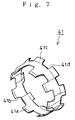
- a fall-out preventing member shown in Fig.7 may be used as a fall-out preventing member 31 attached to the connection ports 7,9 of the tubular joint 5. That is, a fall-out preventing member 41 is made of a metallic thin plate such as elastically deformable stainless steel, etc., and is formed to be cylindrical so as to have a size equivalent to the inner circumferential face of the connection port 7,9, wherein a number of claws 41a are integrally formed at the end part at the tubular connection part 11 side, with notched parts 41b provided therebetween, so that the leading edges of the claws 41a are inclined toward the tubular connection part 11 side and the center side.
- a fall-out preventing member 41 is made of a metallic thin plate such as elastically deformable stainless steel, etc., and is formed to be cylindrical so as to have a size equivalent to the inner circumferential face of the connection port 7,9, wherein a number of claws 41a are integrally formed at the end part at the tubular connection part 11 side, with notched parts
- a number of engaging lugs are folded in the radial direction at the end part at the connection side and notched parts 41d are formed integrally with the engaging lugs 41d therebetween.
- the fall-out preventing member 41 is prevented from coming off by the engaging lugs 41c being engaged in the wall face of the recesses 23,25 when they are inserted in the recesses 23,25 formed on the inner circumferential face of the connection port 7,9.
- the fall-out preventing member 41 prevents the tubes 1,3 and tubular joint 5 from coming off by the claws 41a which are fitted to the outer circumferential face of the tubes 1,3 under pressure causing the leading edge thereof to be engaged in the outer circumferential face of the tubes 1,3 in line with the acting force when a force operates on the tubes 1,3 and tubular joint 5 in their separating direction.
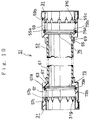
- connection ports 57,59 the inner diameter of which is slightly larger than the outer diameter of tubes 53,55 to be connected and an elastic connection tube 61 which causes the connection ports 57,59 to be connected to each other.
- connection ports 57,59 are formed of synthetic resin of a material which may be identical to or different from that of the tubes 53,55, and staged parts 63,65 whose inner diameter is almost equal to the inner diameter of the tubes 53,55 are integrally formed entirely around the axial line on the inner circumferential face almost at the middle part in the axial direction thereof. Furthermore, cylindrical fixing parts 67,69 whose inner diameter is larger than the inner diameter of tubes 53,55 are integrally formed at the connection ports 57,59 opposite to the connection side.
- An elastic connection tube 61 whose thickness is almost coincident with that of the staged parts 63,65 is integrally formed on the inner circumferential face of the respective fixing parts. That is, the elastic connection tube 61 is molded by welding the same by extruding elastomer resin between the fixing parts 67,69.
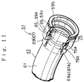
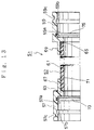
- a number of concave and convex parts 67a, 69a are formed on the inner circumferential face of the respective fixing parts 67,69 as shown in Fig.11, in order to cause the adhering area to be made wider, and a plurality of holes 67b,69b are formed at the respective fixing parts 67,69 as shown in Fig.12 in order to cause a part of the extruded elastomer resin to be filled up in the holes 67b,69b, thereby causing both of them to be firmly adhered to each other.
- an elastic connection tube 61 may be secondarily molded by extruding elastomer resin in such a state that reinforcing meshing fibers 71 such as cylindrically woven metallic fibers, fabric threads or carbon fibers, etc. are provided between the fixing parts 67,69, whereby even though an elastic connection tube 61 is bent, the same is able to maintain its pipe-like shape and the same is able to endure the pressure of fluid flowing therein.
- reinforcing meshing fibers 71 such as cylindrically woven metallic fibers, fabric threads or carbon fibers, etc.
- the abovementioned elastic connection tube 61 is integrally formed at the inner circumferential side of the fixing parts 67,69, the same may be integrally molded so as to put the fixing parts 67,69 therebetween and the same may be made coincident with the outer circumferential face of the connection ports 57,59.
- Attaching recesses 57a,59a are formed around the axial line on the inner circumferential face at the non-connection side of the respective connection ports 57,59, and sealing members 73,75 are integrally molded in the respective attaching recesses 57a,59a.
- Each sealing member 73 or 75 is formed in such a manner that sealing lugs 73b,75b having a length protruding from the inner circumferential face of the connection ports 57,59 are integrally formed on the inner circumference of ring-like members 73a,75a filled up in the attaching recesses 57a,59a, and elastomer resin is extruded in the attaching recesses 57a,59a to cause the sealing members 73,75 to be welded therein. Furthermore, the sealing members 73,75 may be simultaneously molded when secondarily molding the elastic connection tube 61 at the connection ports 57,59.
- Recesses 57,59 are formed around the axial line on the inner circumferential face at the connection side at the respective connection ports 57,59 and parts 57c,59c to be engaged are formed around the axial line on the outer circumferential face at a point which is almost coincident with the respective recesses 57,59.
- a fall-out preventing member 31 is inserted into the connection side edge part of the respective connection ports 57,59.
- Each fall-out preventing member 31 is similar to the fall-out preventing member 31 described in the first preferred embodiment. Therefore, the same reference number is given, and the description thereof is omitted herein. Furthermore, although the drawings show fall-out preventing members 31, fall-out preventing members 41 shown in Fig.7 may be also used.
- claws 31g of the respective fall-out preventing members 31 are elastically deformed in the diameter-swelling direction in the recesses 57b,59b in line with insertion thereof into the end parts of the tubes 53,55, whereby the insertion thereof is enabled, and on the other hand, the claws 31g are fitted to the outer circumferential face at the end parts of the tubes 53,55 by an elastic returning force after the insertion is completed.
- sealing members 73,75 are made airtight by sealing lugs 53b,75b pressure-fitted to the end part outer circumferential face of the tubes 53,55 when the insertion is finished.
- tubular joint 51 is composed so that connection ports 7,9,57,59 are provided at both the ends of the tubular connection part 11 and elastic connection tube 61
- tubular connection part 11 and elastic connection tube 61 may be either of Y-shape, cross-shape, or any shape having any desired curvature, which is provided with three or more connection ports.
Landscapes
- Engineering & Computer Science (AREA)
- General Engineering & Computer Science (AREA)
- Mechanical Engineering (AREA)
- Quick-Acting Or Multi-Walled Pipe Joints (AREA)
- Joints That Cut Off Fluids, And Hose Joints (AREA)
Abstract
Description
- The present invention relates to a tubular joint for connecting tubes or pipes to each other.
- For example, in a case where synthetic resin tubes (pipes) are connected to each other, a tubular joint having a connection port, whose inner diameter is almost equal to the outer diameter of said tube, at both ends thereof is inserted to an end on which an adhesive agent is coated and is fixed thereon. The tube and tubular joints thus connected are made airtight by the adhesive agent inserted therebetween.
- However, when obtaining the airtightness with an adhesive agent, such an adhesive agent must be almost uniformly coated on the end part of a tube and the connection port of the tubular joint. This is very cumbersome. Especially, if tubes are intended to be disposed in a narrow space such as behind ceilings or inside walls, it is very difficult to coat such an adhesive agent thereon, and the working efficiency is very bad.
- When attaching a tubular joint to a tube, part of the coated adhesive agent is peeled off to cause the coating thereof not to be uniform or sufficient, whereby the airtightness is made incomplete and the connection is not made tough.
- In order to address the abovementioned shortcomings and drawbacks, a ring-like sealing member may be attached to the inner circumferential face of a connection port. However, in this case, the attaching work of sealing members needs much manpower and time, thereby causing the production cost to be increased.
- Furthermore, in a case of connecting tubes which are separated or spaced from each other or the axial directions of which are different from each other, it is necessary to use a tubular joint bent in advance at an appointed angle, and various kinds of tubular joints having different bent angles must be prepared. In addition, it is necessary to bend tubular joints in compliance with the arranging states of tubes or pipes to be connected at a site work. Therefore, the working efficiency is worse and much time is required for the site working.
- The present invention is as claimed in the claims.
- The invention was developed in order to address the abovementioned shortcomings and drawbacks.
- Embodiments of the invention to provide a tubular joint by which tubes or pipes may be securely connected in a short time even in a narrow space, thereby causing the site working efficiency to be much improved.
- Embodiments of the invention may provide a tubular pipe by which water or liquid leakage at a connection port is reliable and secure and the connection state is securely maintained for a longer period of time, a tubular pipe which does not need any attaching work of sealing material at connection ports, thereby causing the production cost to be much decreased, or a tubular joint by which tubes or pipes in different arranged states can be connected to each other with only a single kind thereof.
- Other advantages of the invention will be readily appreciated as the same becomes better understood by reference to the following detailed description of exemplary preferred embodiments when considered in connection with the accompanying drawings wherein:
- FIG.1 is a partially broken perspective view of a tubular joint.
- FIG.2 is a longitudinally sectional view of said tubular joint.
- FIG.3 is a longitudinally sectional view showing a modified embodiment of said tubular joint.
- FIG.4 is a perspective view of a fall-out preventing member.
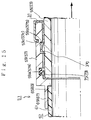
- FIG.5 is a longitudinally sectional view showing a connected state of tubes.
- FIG.6 is a partially enlarged longitudinally sectional view showing a fall-out stopped state.
- FIG.7 is a perspective view showing a modified example of said fall-out preventing member.
- FIG.8 is a partially enlarged longitudinally sectional view showing a fall-out stopped state.
- FIG. 9 is a perspective view of an entire tubular joint.
- FIG.10 is a longitudinally sectional view taken along the line II-II in Fig.9.
- FIG.11 is a partially broken perspective view showing a fixed state of an elastic connection tube.
- FIG.12 is a partially broken perspective view showing a fixed state of an elastic connection tube.
- FIG.13 is a partially longitudinally sectional view showing a modified example of an elastic connection tube.
- FIG.14 is a partially enlarged longitudinally sectional view showing a connected state of a tube and a tubular joint.
- FIG.15 is a partially enlarged longitudinally sectional view showing a fall-out stopped state.
- In Fig.1 to Fig.4, a
joint body 6 of atubular joint 5 which mutually connectssynthetic resin tubes 1 and 3 having an appointed inner diameter and an appointed outer diameter is made of synthetic resin which may be identical to the material ofsaid tubes 1,3 or different therefrom and is formed integrally withconnection ports tubular connection part 11 which connectssaid connection ports said connection ports tubes 1,3 and at the same time saidtubular connection part 11 is formed so as to have an inner diameter which is almost coincident with the inner diameter ofsaid tubes 1,3. Furthermore, although thejoint body 6 is constructed so that the same is connected by atubular connection part 11, the inner diameter of which is different from that ofsaid connection ports tubular joint 5 may be such that saidconnection ports tubular connection part 11, the outer diameter of which is almost equal to that ofsaid connection ports tubes 1,3 is formed around the axial line on the inner circumferential face at the middle part in the axial direction of thetubular connection part 11. - Attaching
recesses connection parts tubular connection 11 side, and sealingmembers members like members recesses lugs connection ports like members tubular joint 5 or a method of secondary molding onto atubular joint 5 molded in advance may be adopted as a molding pattern of said sealingmembers members single sealing lug member -
Recesses respective connection ports recesses members respective connection ports members connection ports protrusion lugs 31b extending along the outer circumferential face of thetubular joint 5 to reach theparts notched parts 31c provided therebetween around the axial line, and the leading edge of each of saidprotrusion lugs 31b is folded to be engaged with thepart protrusion lugs 31b to be engaged with theparts protrusion lugs 31b so as to be engaged with theparts protrusion lugs 31b located at theparts - On the other hand, a number of
protrusion jugs 31e extending along the inner circumferential face of saidtubular joint 5 to reach therecesses cylindrical part 31d of the respective fall-out preventing member 31 withnotched parts 31f provided therebetween around the axial line, andclaws 31g are formed at the leading edge of therespective protrusion jugs 31e. The leading edge of each of theclaws 31g is sharp and is folded to be oblique toward thetubular connection part 11 side and the center side thereof. - Next, a description is given of a connection method of mutual tubes by a tubular joint.
- In Fig.5 and Fig. 6 if one
connection port 7 at thetubular joint 5 is inserted relative to the end face at one tube 1 so that the end face of the one tube 1 is brought into contact with a staged part located at the boundary between thetubular connection part 11 and theconnection port 7, as shown in Fig.5, the sealinglug 19b of sealingmember 19 is brought into contact with the outer circumferential face of the tube 1 under pressure while the same is making elastic deformations, whereby the airtightness between the tube 1 and thetubular joint 5 is maintained. At this time, since theclaw 31g of the fall-outmember 31 is inclined in the insertion direction of the tube 1, the same is elastically deformed in the diameter-swelling direction in therecess 23 in line with the insertion thereof, thereby enabling the insertion. On the other hand, after the insertion is completed, theclaw 31g is brought into contact with the outer circumferential face under pressure due to elasticity return, thereby causing the inserted state to be maintained. The end part of theother tube 3 is inserted, as in the above, in theother connection port 9 in thetubular joint 5 attached to the other tube 1, whereby thetubes 1,3 are able to be connected to each other. - Next, in the above connected state, when a force operates on the
tubes 1,3 andtubular joint 5 in such a direction that they are separated from each other, the leading edge of theclaws 31g of the fall-out preventing member 31 are engaged with the outer circumferential face of thetubes 1,3 in line with the force operating as shown in Fig.6 since theclaw 31g is brought into contact with the outer circumferential face of thetubes 1,3 in such a state that theclaw 31g is inclined in the direction opposite to the separation direction, whereby the leading edge thereof is prevented from being separated from thetubes 1,3 and their connected state is able to be maintained. - A fall-out preventing member shown in Fig.7 may be used as a fall-
out preventing member 31 attached to theconnection ports tubular joint 5. That is, a fall-out preventing member 41 is made of a metallic thin plate such as elastically deformable stainless steel, etc., and is formed to be cylindrical so as to have a size equivalent to the inner circumferential face of theconnection port claws 41a are integrally formed at the end part at thetubular connection part 11 side, with notched parts 41b provided therebetween, so that the leading edges of theclaws 41a are inclined toward thetubular connection part 11 side and the center side. Furthermore, a number of engaging lugs are folded in the radial direction at the end part at the connection side and notchedparts 41d are formed integrally with theengaging lugs 41d therebetween. The fall-out preventing member 41 is prevented from coming off by the engaging lugs 41c being engaged in the wall face of therecesses recesses connection port - As shown in Fig.8, the fall-
out preventing member 41 prevents thetubes 1,3 andtubular joint 5 from coming off by theclaws 41a which are fitted to the outer circumferential face of thetubes 1,3 under pressure causing the leading edge thereof to be engaged in the outer circumferential face of thetubes 1,3 in line with the acting force when a force operates on thetubes 1,3 andtubular joint 5 in their separating direction. - In Fig.9 through Fig.13, the
joint body 52 of atubular joint 51 is comprised ofconnection ports tubes elastic connection tube 61 which causes theconnection ports - The
connection ports tubes parts tubes cylindrical fixing parts tubes connection ports - An
elastic connection tube 61 whose thickness is almost coincident with that of the stagedparts elastic connection tube 61 is molded by welding the same by extruding elastomer resin between thefixing parts elastic connection tube 61 on thefixing parts convex parts respective fixing parts holes 67b,69b are formed at therespective fixing parts holes 67b,69b, thereby causing both of them to be firmly adhered to each other. Furthermore, as shown in Fig.13, anelastic connection tube 61 may be secondarily molded by extruding elastomer resin in such a state that reinforcingmeshing fibers 71 such as cylindrically woven metallic fibers, fabric threads or carbon fibers, etc. are provided between the fixingparts elastic connection tube 61 is bent, the same is able to maintain its pipe-like shape and the same is able to endure the pressure of fluid flowing therein. Furthermore, although the abovementionedelastic connection tube 61 is integrally formed at the inner circumferential side of the fixingparts parts connection ports - Attaching
recesses respective connection ports members recesses member lugs connection ports like members 73a,75a filled up in the attachingrecesses recesses members members elastic connection tube 61 at theconnection ports -
Recesses respective connection ports parts respective recesses member 31 is inserted into the connection side edge part of therespective connection ports - Each fall-out preventing
member 31 is similar to the fall-out preventingmember 31 described in the first preferred embodiment. Therefore, the same reference number is given, and the description thereof is omitted herein. Furthermore, although the drawings show fall-out preventingmembers 31, fall-out preventingmembers 41 shown in Fig.7 may be also used. - Next, a description is given of a method for connecting
tubes - In Fig.14, and Fig.15, in a case where
tubes respective tubes connection ports elastic connection tube 61 is elastically deformed relative to the end parts thereof according to the separated or spaced state oftubes claws 31g of the respective fall-out preventingmembers 31 are elastically deformed in the diameter-swelling direction in therecesses tubes claws 31g are fitted to the outer circumferential face at the end parts of thetubes members lugs 53b,75b pressure-fitted to the end part outer circumferential face of thetubes - When a force operates on the
tubes claws 31g pressure-fitted to the outer circumferential face of thetubes tubes tubes - In the above description, although the tubular joint 51 is composed so that
connection ports tubular connection part 11 andelastic connection tube 61, thetubular connection part 11 andelastic connection tube 61 may be either of Y-shape, cross-shape, or any shape having any desired curvature, which is provided with three or more connection ports.
Claims (7)
- A tubular joint comprising a synthetic resin made joint body in which at least a pair of connection ports having an inner diameter which is insertable into the end part of a tube are connected by a tubular connection part, and sealing members integrally formed with elastomer resin onto the inner circumferential face of the respective connection ports, wherein when the respective connection ports are inserted into the end parts of each tube to be connected, elastically deformable sealing members are pressure-fitted to the outer circumferential face of the end parts to enable an airtight connection.
- A tubular joint as set forth in claim 1, wherein when said sealing member is integrally molded by extruding elastomer resin in a recess formed on the inner circumferential face at a connection port, said sealing member is formed of a sealing lug protruding from a ring-like part filled up in said recess and the inner circumferential face thereof.
- A tubular joint as set forth in claim 1, wherein said tubular connection part is integrally molded to be elastically deformable by extruding elastomer resin in a connection port molded in advance.
- A tubular joint as set forth in claim 3, wherein said sealing member and tubular connection part are simultaneously integrally molded by extruding elastomer resin in a connection port molded in advance.
- A tubular joint as set forth in claim 1, wherein a fall-out preventing member having elastically deformable claws inclined toward the direction opposite to the insertion direction relative to a tube at the inner circumferential face and toward the center direction is provided at the respective connection ports and fall-out prevention is possible by said claws pressure-fitted to the outer circumferential face of said tube after the insertion is completed while the insertion of a connection port into the tube end part is made possible.
- A tubular joint as set forth in claim 5, wherein said fall-out preventing member is formed to be of a double-cylindrical shape which is insertable in the end part of the respective connection ports and has engaging parts which are engageable with the part to be engaged, provided at the outer circumferential face of each connection port and claws extending along the inner circumferential face of said connection ports and able to be caught in the outer circumferential face of a tube.
- A tubular joint as set forth in claim 5, wherein said fall-out preventing member is formed to be of a cylindrical shape which is insertable in recesses provided on the inner circumferential face of each connection port and has an engaging part engageable in said recesses for preventing fall-out and claws extending along the inner circumferential face of said connection port and able to be caught in the outer circumferential face of a tube.
Applications Claiming Priority (4)
| Application Number | Priority Date | Filing Date | Title |
|---|---|---|---|
| JP7274714A JPH0989178A (en) | 1995-09-27 | 1995-09-27 | Connecting structure for pipe |
| JP274714/95 | 1995-09-27 | ||
| JP28941595A JPH09105492A (en) | 1995-10-09 | 1995-10-09 | Pipe joint |
| JP289415/95 | 1995-10-09 |
Publications (2)
| Publication Number | Publication Date |
|---|---|
| EP0767337A2 true EP0767337A2 (en) | 1997-04-09 |
| EP0767337A3 EP0767337A3 (en) | 1999-03-31 |
Family
ID=26551161
Family Applications (1)
| Application Number | Title | Priority Date | Filing Date |
|---|---|---|---|
| EP96306251A Withdrawn EP0767337A3 (en) | 1995-09-27 | 1996-08-29 | Tubular joint |
Country Status (2)
| Country | Link |
|---|---|
| US (1) | US5681062A (en) |
| EP (1) | EP0767337A3 (en) |
Cited By (5)
| Publication number | Priority date | Publication date | Assignee | Title |
|---|---|---|---|---|
| EP1041332A1 (en) * | 1999-03-31 | 2000-10-04 | Kunimorikagaku LTD | Plastic tubular joint with plastic grip-ring |
| EP1962009A1 (en) | 2007-02-01 | 2008-08-27 | IBP Conex Limited | Pipe fitting arrangement and method for forming the same |
| WO2009108963A3 (en) * | 2008-02-26 | 2009-11-12 | Hendrik Jakobus Van Wyk | Pipe fitting |
| CN102052539A (en) * | 2010-10-28 | 2011-05-11 | 浙江大学 | Pipeline electric fusing joint adopting tenon-and-mortise structure and electric fusing welding method |
| CN110657305A (en) * | 2019-09-29 | 2020-01-07 | 谭连平 | Combined sealing connection method for plastic pipes |
Families Citing this family (50)
| Publication number | Priority date | Publication date | Assignee | Title |
|---|---|---|---|---|
| GB9712290D0 (en) * | 1997-06-12 | 1997-08-13 | Guest John D | Improvements in or relating to collets for locking tubes in coupling bodies |
| KR100635244B1 (en) * | 1998-12-18 | 2006-10-19 | 아코르 테크놀로지 인코포레이티드 | Tube coupling |
| JP2001050457A (en) * | 1999-08-03 | 2001-02-23 | Smc Corp | Tube joint |
| US6765143B2 (en) * | 2001-07-09 | 2004-07-20 | Bridgeport Fittings, Inc. | Tubing and conduit coupling or connector assembly |
| US6976712B2 (en) * | 2002-04-17 | 2005-12-20 | Micromold Products Inc. | Corrosion-resistant coupling means and methods for using same |
| US6719330B2 (en) * | 2002-06-18 | 2004-04-13 | Qest | Flexible tubing/fitting connection |
| US6857667B2 (en) * | 2002-06-25 | 2005-02-22 | Itt Manufacturing Enterprises, Inc. | High pressure fluid quick connect |
| US20050040650A1 (en) * | 2003-08-18 | 2005-02-24 | Chang Tuan Hsu | Easy assembled tube connector |
| US20060125236A1 (en) * | 2004-12-15 | 2006-06-15 | Victaulic Company Of America | Retainer with inward projections |
| US20060175831A1 (en) * | 2005-02-10 | 2006-08-10 | Itt Manufacturing Enterprises, Inc. | Fluid quick connect contamination cover |
| US7448653B2 (en) | 2005-06-10 | 2008-11-11 | Value Plastics, Inc. | Female connector for releasable coupling with a male connector defining a fluid conduit |
| ES2322377T3 (en) * | 2005-07-03 | 2009-06-19 | Widee B.V. | COUPLING BETWEEN TWO TUBES WITH SEPARATE ADJUSTMENT CLAMPS. |
| US7806139B2 (en) | 2006-01-20 | 2010-10-05 | Value Plastics, Inc. | Fluid conduit coupling assembly having male and female couplers with integral valves |
| US9611958B1 (en) | 2007-01-05 | 2017-04-04 | Zurn Industries, Llc | Combination mechanical/fusion pipe fitting with push connect coupling arrangement |
| USD654573S1 (en) | 2007-11-19 | 2012-02-21 | Value Plastics, Inc. | Female quick connect fitting |
| US20090278346A1 (en) * | 2008-05-07 | 2009-11-12 | O'brien Kevin | Connector |
| US8235426B2 (en) | 2008-07-03 | 2012-08-07 | Nordson Corporation | Latch assembly for joining two conduits |
| USD655393S1 (en) | 2009-06-23 | 2012-03-06 | Value Plastics, Inc. | Multi-port valve |
| US9388929B2 (en) | 2009-12-09 | 2016-07-12 | Nordson Corporation | Male bayonet connector |
| USD783815S1 (en) | 2009-12-09 | 2017-04-11 | General Electric Company | Male dual lumen bayonet connector |
| US10711930B2 (en) | 2009-12-09 | 2020-07-14 | Nordson Corporation | Releasable connection assembly |
| USD650478S1 (en) | 2009-12-23 | 2011-12-13 | Value Plastics, Inc. | Female dual lumen connector |
| USD649240S1 (en) | 2009-12-09 | 2011-11-22 | Value Plastics, Inc. | Male dual lumen bayonet connector |
| SG181932A1 (en) | 2009-12-23 | 2012-07-30 | Nordson Corp | Button latch with integrally molded cantilever springs |
| JP5714028B2 (en) | 2009-12-23 | 2015-05-07 | ノードソン コーポレーションNordson Corporation | Fluid connector latch with profile retraction |
| USD652511S1 (en) | 2011-02-11 | 2012-01-17 | Value Plastics, Inc. | Female body of connector for fluid tubing |
| USD652510S1 (en) | 2011-02-11 | 2012-01-17 | Value Plastics, Inc. | Connector for fluid tubing |
| USD663022S1 (en) | 2011-02-11 | 2012-07-03 | Nordson Corporation | Male body of connector for fluid tubing |
| USD698440S1 (en) | 2011-07-29 | 2014-01-28 | Nordson Corporation | Connector for fluid tubing |
| USD699841S1 (en) | 2011-07-29 | 2014-02-18 | Nordson Corporation | Female body of connector for fluid tubing |
| USD699840S1 (en) | 2011-07-29 | 2014-02-18 | Nordson Corporation | Male body of connector for fluid tubing |
| USD709612S1 (en) | 2011-12-23 | 2014-07-22 | Nordson Corporation | Female dual lumen connector |
| US9120111B2 (en) | 2012-02-24 | 2015-09-01 | Rain Bird Corporation | Arc adjustable rotary sprinkler having full-circle operation and automatic matched precipitation |
| US9156043B2 (en) | 2012-07-13 | 2015-10-13 | Rain Bird Corporation | Arc adjustable rotary sprinkler with automatic matched precipitation |
| US8801048B2 (en) | 2012-11-27 | 2014-08-12 | Charlotte Pipe And Foundry Company | Mechanical pipe coupling assembly without adhesive or bonding agent |
| US10578234B2 (en) | 2013-05-02 | 2020-03-03 | Victaulic Company | Coupling having arcuate stiffness ribs |
| DE102015226452A1 (en) * | 2015-12-22 | 2017-06-22 | Robert Bosch Gmbh | Valve for metering a fluid |
| DK3397884T3 (en) | 2015-12-28 | 2020-08-03 | Victaulic Co Of America | ADAPTER CLUTCH |
| US10533688B2 (en) | 2016-05-16 | 2020-01-14 | Victaulic Company | Coupling having tabbed retainer |
| US10605394B2 (en) | 2016-05-16 | 2020-03-31 | Victaulic Company | Fitting having tabbed retainer and observation apertures |
| US10859190B2 (en) | 2016-05-16 | 2020-12-08 | Victaulic Company | Sprung coupling |
| USD838366S1 (en) | 2016-10-31 | 2019-01-15 | Nordson Corporation | Blood pressure connector |
| US10920892B2 (en) | 2018-09-18 | 2021-02-16 | Accor Technology, Inc. | Adapter for connecting tubing with push-fit fittings |
| US10865923B2 (en) | 2018-11-19 | 2020-12-15 | Accor Technology, Inc. | Push-fit fitting and end bushing for use therewith |
| WO2020121955A1 (en) | 2018-12-11 | 2020-06-18 | 日東工器株式会社 | Connecting pipe |
| US11149426B2 (en) | 2019-06-12 | 2021-10-19 | Charlotte Pipe And Foundry Company | Toilet assembly having improved closet flange |
| US11781683B2 (en) | 2019-11-15 | 2023-10-10 | Victaulic Company | Shrouded coupling |
| US12343748B2 (en) | 2021-03-16 | 2025-07-01 | Rain Bird Corporation | Multi-mode rotor sprinkler apparatus and method |
| US12434252B2 (en) | 2022-04-20 | 2025-10-07 | Rain Bird Corporation | Full-circle and part-circle rotor sprinkler |
| US12440855B2 (en) | 2022-10-27 | 2025-10-14 | Rain Bird Corporation | Multi-mode rotor sprinkler apparatus and method |
Family Cites Families (13)
| Publication number | Priority date | Publication date | Assignee | Title |
|---|---|---|---|---|
| GB1236907A (en) * | 1969-02-25 | 1971-06-23 | Hepworth Iron Co Ltd | Improvements in or relating to pipe couplings |
| GB1312782A (en) * | 1969-12-04 | 1973-04-04 | Hepworth Iron Co Ltd | Pipe couplings |
| FR2142224A6 (en) * | 1971-06-17 | 1973-01-26 | Plastic Omnium Cie | Plastic pressure pipe coupling - incorporating a split skirt seal retained by a captive champhered split ring |
| US3920270A (en) * | 1973-10-03 | 1975-11-18 | Jr Howard R Babb | Pipe coupling |
| GB1445822A (en) * | 1974-01-31 | 1976-08-11 | Naylor Bros Clayware Ltd | Pipe couplings |
| GB1477074A (en) * | 1975-01-31 | 1977-06-22 | Hepworth Iron Co Ltd | Manufacture of pipe couplings |
| US4146254A (en) * | 1976-03-31 | 1979-03-27 | Bristol Products, Inc. | Coupler for tubing |
| GB2075141A (en) * | 1980-05-01 | 1981-11-11 | British Steel Corp | Pipe joints and pipe couplings |
| IL61576A0 (en) * | 1980-11-27 | 1980-12-31 | Plasson Maagan Michael Ind Ltd | Pipe coupling |
| EP0060310B1 (en) * | 1981-03-12 | 1985-07-17 | WOCO Franz-Josef Wolf & Co. | Insert sleeve |
| GB2177176B (en) * | 1985-07-01 | 1989-09-06 | Naylor Bros | Pipe connector |
| WO1990010171A1 (en) * | 1989-03-03 | 1990-09-07 | Storm Plastics (Sa) Pty. Ltd. | Pipe joint |
| DE9420519U1 (en) * | 1994-02-14 | 1995-02-09 | Geberit Technik Ag, Jona | Pipe connector |
-
1996
- 1996-08-05 US US08/692,384 patent/US5681062A/en not_active Expired - Fee Related
- 1996-08-29 EP EP96306251A patent/EP0767337A3/en not_active Withdrawn
Cited By (6)
| Publication number | Priority date | Publication date | Assignee | Title |
|---|---|---|---|---|
| EP1041332A1 (en) * | 1999-03-31 | 2000-10-04 | Kunimorikagaku LTD | Plastic tubular joint with plastic grip-ring |
| EP1962009A1 (en) | 2007-02-01 | 2008-08-27 | IBP Conex Limited | Pipe fitting arrangement and method for forming the same |
| WO2009108963A3 (en) * | 2008-02-26 | 2009-11-12 | Hendrik Jakobus Van Wyk | Pipe fitting |
| CN102052539A (en) * | 2010-10-28 | 2011-05-11 | 浙江大学 | Pipeline electric fusing joint adopting tenon-and-mortise structure and electric fusing welding method |
| CN102052539B (en) * | 2010-10-28 | 2012-08-22 | 浙江大学 | Pipeline electric fusing joint adopting tenon-and-mortise structure and electric fusing welding method |
| CN110657305A (en) * | 2019-09-29 | 2020-01-07 | 谭连平 | Combined sealing connection method for plastic pipes |
Also Published As
| Publication number | Publication date |
|---|---|
| EP0767337A3 (en) | 1999-03-31 |
| US5681062A (en) | 1997-10-28 |
Similar Documents
| Publication | Publication Date | Title |
|---|---|---|
| US5681062A (en) | Tubular joint | |
| US6158784A (en) | Connector for tubular members | |
| CN100458257C (en) | Plug-in fittings | |
| CA2026196C (en) | Fitting for corrugated tubing | |
| US6231090B1 (en) | Tubular joint | |
| JP4240304B2 (en) | Barb clamp | |
| CN1322263C (en) | Rotatable quick connector | |
| CA1278536C (en) | Plastic corrugated tube with integrally molded sleeve coupler | |
| US5513882A (en) | Universal non-threaded pipe connector system | |
| JPH06341586A (en) | Duplex type joint for connecting pipe | |
| JP4837458B2 (en) | Quick connector | |
| JPH0235190B2 (en) | ||
| JPH0211993A (en) | Hose joint | |
| JPH05280680A (en) | Fluid coupling | |
| US20130214528A1 (en) | Hose-line connector and line assembly | |
| US5762380A (en) | Pipe joint with flanged housings | |
| US3820826A (en) | Fitting structure for pipe | |
| KR100856472B1 (en) | Connection system with coaxial end sections of two fluid lines that are to be joined | |
| US5310225A (en) | Clamping connection made of plastic | |
| JPH0211995A (en) | hose fittings | |
| CN100396985C (en) | hose connector | |
| KR0145311B1 (en) | Couplings for quick tube connection | |
| EP3736480A1 (en) | Coupling assembled with hairpins | |
| CN209743844U (en) | pipeline connection structure, engine pipeline and vehicle | |
| GB2158907A (en) | Hose end fittings |
Legal Events
| Date | Code | Title | Description |
|---|---|---|---|
| PUAI | Public reference made under article 153(3) epc to a published international application that has entered the european phase |
Free format text: ORIGINAL CODE: 0009012 |
|
| AK | Designated contracting states |
Kind code of ref document: A2 Designated state(s): DE ES FR GB IT |
|
| PUAL | Search report despatched |
Free format text: ORIGINAL CODE: 0009013 |
|
| AK | Designated contracting states |
Kind code of ref document: A3 Designated state(s): DE ES FR GB IT |
|
| 17P | Request for examination filed |
Effective date: 19990828 |
|
| 17Q | First examination report despatched |
Effective date: 20000922 |
|
| GRAG | Despatch of communication of intention to grant |
Free format text: ORIGINAL CODE: EPIDOS AGRA |
|
| GRAG | Despatch of communication of intention to grant |
Free format text: ORIGINAL CODE: EPIDOS AGRA |
|
| GRAH | Despatch of communication of intention to grant a patent |
Free format text: ORIGINAL CODE: EPIDOS IGRA |
|
| GRAH | Despatch of communication of intention to grant a patent |
Free format text: ORIGINAL CODE: EPIDOS IGRA |
|
| STAA | Information on the status of an ep patent application or granted ep patent |
Free format text: STATUS: THE APPLICATION IS DEEMED TO BE WITHDRAWN |
|
| 18D | Application deemed to be withdrawn |
Effective date: 20030301 |