EP0767128A2 - Clutch mechanism of coat film transfer tool and coat film transfer tool - Google Patents
Clutch mechanism of coat film transfer tool and coat film transfer tool Download PDFInfo
- Publication number
- EP0767128A2 EP0767128A2 EP96307297A EP96307297A EP0767128A2 EP 0767128 A2 EP0767128 A2 EP 0767128A2 EP 96307297 A EP96307297 A EP 96307297A EP 96307297 A EP96307297 A EP 96307297A EP 0767128 A2 EP0767128 A2 EP 0767128A2
- Authority
- EP
- European Patent Office
- Prior art keywords
- coat film
- film transfer
- tape
- clutch mechanism
- engaging
- Prior art date
- Legal status (The legal status is an assumption and is not a legal conclusion. Google has not performed a legal analysis and makes no representation as to the accuracy of the status listed.)
- Granted
Links
Images


Classifications
-
- B—PERFORMING OPERATIONS; TRANSPORTING
- B65—CONVEYING; PACKING; STORING; HANDLING THIN OR FILAMENTARY MATERIAL
- B65H—HANDLING THIN OR FILAMENTARY MATERIAL, e.g. SHEETS, WEBS, CABLES
- B65H37/00—Article or web delivery apparatus incorporating devices for performing specified auxiliary operations
- B65H37/002—Web delivery apparatus, the web serving as support for articles, material or another web
- B65H37/005—Hand-held apparatus
- B65H37/007—Applicators for applying coatings, e.g. correction, colour or adhesive coatings
Definitions
- the present invention relates to a clutch mechanism of a coat film transfer tool, and a coat film transfer tool comprising this clutch mechanism, and more particularly to a clutch technology for synchronizing the feed speed and take-up speed of coat film transfer tape in a feed reel and a take-up reel, in a coat film transfer tool for transferring a coat film such as corrective paint layer, adhesive layer or the like on a coat film transfer tape onto a sheet of paper or the like, and automatically collecting the coat film transfer tape after use.
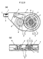
- FIG. 21 An example of structure of this kind of coat film transfer tool is shown in Fig. 21, and in this transfer tool, in a case (a) that can be held and manipulated by a single hand, a feed reel (c) with a coat film transfer tape (b) wound thereabout and a take-up reel (d) for collecting the coat film transfer tape (b') after use are rotatably provided, and a coat film transfer head (f) for pressing the coat film transfer tape (b) onto the object of transfer is protruding at the front end of the case (a).
- the both reels (c) and (d) are wound up automatically as being linked by an interlock mechanism (g) so as to cooperate with each other.
- gears (h) and (i) provided on the outer circumference of the both reels (c) and (d) are engaged with each other.
- this coat film transfer tool When this coat film transfer tool is used as an erasing tool for correcting a wrong letter or the like, the case (a) is held by one hand, and moved in a desired direction while pressing the coat film transfer tape (b) tightly to the correction area (the object of transfer) by a pressing portion (j) of the head (f). As a result, the corrective paint layer of the coat film transfer tape (b) in the pressing portion (j) of the head (f) is applied on the correction area, and the letter is deleted, and the coat film transfer tape (b') after use is automatically wound up and collected by the take-up reel (d).
- the outer diameter of the coat film transfer tape (b) on the feed reel (c) becomes smaller, while the outer diameter of the coat film transfer tape (b') on the take-up reel (d) becomes larger.
- the rotation ratio of the feed reel (c) and take-up reel (d) is always constant.
- the take-up speed of the take-up reel (d) tends to be faster gradually as compared with the feed speed of the feed reel (c), and to prevent this, therefore, it is necessary to synchronize the feed speed and take-up speed.
- the feed reel (c) is provided with a clutch mechanism (k) for synchronizing the feed speed and take-up speed.
- a boss (m) of a drive gear (h) rotatably supported on a support shaft (n), and a tape feed core (o) with the coat film transfer tape (b) wound thereabout is rotatably fitted on the boss (m), and the clutch mechanism (k) is provided between the boss (m) and the tape feed core (o).
- the clutch mechanism (k) causes the tape feed core (o) to slide and rotate on the boss (m), so that the feed speed is synchronized with the take-up speed.
- a clutch mechanism (r) as shown in Fig. 22 (see, for example, Japanese Laid-open Patent No. 5-58097).
- a circular elastic friction member (s) such as O-ring is interposed between the cylindrical outer circumference of the boss (m) and the cylindrical inner circumference of the tape feed core (o) in a frictionally engaged state.
- the frictional force must be set at an optimum value.
- the clutch mechanism of the invention is for use in a coat film transfer tool of automatic winding type comprising a feed reel with a coat film transfer tape wound thereabout and a take-up reel for collecting the coat film transfer tape after use, rotatably provided in a case that can be held and manipulated by one hand, in which thetake-up reel cooperates with the feed reel, for synchronizing the feed speed and take-up speed of the coat film transfer tape in both reels, wherein power transmission means between a tape winding portion for winding up the coat film transfer tape and a rotary drive unit for rotating and driving this tape winding portion is composed in at least one of the two reels, and power transmission of the power transmission means makes use of the frictional force by the thrust load between the tape winding portion and the rotary drive unit, and is connected and disconnected by the difference in torque between these two members.
- the coat film transfer tool of the invention comprises a case having shape and dimensions to be held and manipulated by one hand, a feed reel rotatably provided in the case and winding a coat film transfer tape, a take-up reel rotatably provided in the case for collecting the coat film transfer tape after use, an interlock mechanism for linking these two reels so as to cooperate with each other, and a coat film transfer head protruding at the front end of the case for pressing the coat film transfer tape onto the object of transfer, further comprising said clutch mechanism at least in one of the two reels.
- the coat film transfer tool comprising the clutch mechanism is classified into the disposable type to be discarded when the coat film transfer tape is used up, and the refill type that can be used repeatedly only by replacing the spent coat film transfer tape with a new one.
- the take-up speed of the take-up reel gradually becomes faster as compared with the feed speed of the feed reel, and their synchronism is broken to increase the torque acting on the tape winding portion for winding the coat film transfer tape, and herein the clutch mechanism acts to cause the tape winding portion to slide and rotate on the rotary drive unit to eliminate the torque difference between the two, so that the feed speed is synchronized with the take-up speed.
- the power transmission in the clutch mechanism makes use of the frictional force by thrust load between the tape winding portion and the rotary drive unit, and therefore the structual components relatively slide smoothly in this synchronizing action.
- the frictional force can be set at an optimum value.
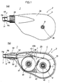
- Fig. 1 (a) is a front view showing the appearance of a coat film transfer type of refill type in embodiment 1 of the invention.
- Fig. 1 (b) is a front view showing the internal structure of the coat film transfer tool by removing the cover body.
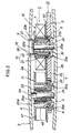
- Fig. 2 is a longitudinal sectional view showing an essential structure of the coat film transfer tool.
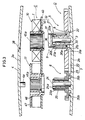
- Fig. 3 is a longitudinal view showing a disassembled state of the essential structure of the coat film transfer tool.
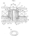
- Fig. 4 (a) is a magnified longitudinal sectional view showing the engaging state of a clutch mechanism which is an essential part in a tape drive unit of the coat film transfer tool.
- Fig. 4 (b) is a perspective view showing an O-ring in the clutch mechanism.
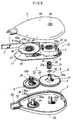
- Fig. 5 is a perspective exploded view of the coat film transfer tool.
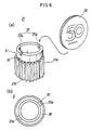
- Fig. 6 (a) is a perspective view showing a rewinding operation unit in the tape drive unit.
- Fig. 6 (b) is a plan view showing the rewinding operation unit.
- Fig. 7 is a perspective view showing the operating state of the coat film transfer tool.
- Fig. 8 (a) is a longitudinal sectional view showing essential parts of a tape drive unit in a refill type coat film transfer tool in embodiment 2 of the invention.
- Fig. 8 (b) is a magnified longitudinal sectional view of a clutch mechanism as the essential part.
- Fig. 9 (a) is a longitudinal sectional view showing essential parts of a tape drive unit in a refill type coat film transfer tool in embodiment 3 of the invention.
- Fig. 9 (b) is a perspective view showing a sheet of a clutch mechanism as the essential part.
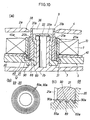
- Fig. 10 (a) is a longitudinal sectional view showing essential parts of a tape drive unit in a refill type coat film transfer tool in embodiment 4 of the invention.
- Fig. 10 (b) is a plan view showing a second engaging portion of a clutch mechanism as the essential part.
- Fig. 10 (c) is a magnified longitudinal sectional view showing the engaging state of first and second engaging portions of the clutch mechanism.
- Fig. 11 (a) is a longitudinal sectional view showing essential parts of a tape drive unit in a refill type coat film transfer tool in embodiment 5 of the invention.
- Fig. 11 (b) is a plan view showing a second engaging portion of a clutch mechanism as the essential part.
- Fig. 11 (c) is a magnified longitudinal sectional view showing the engaging state of first and second engaging portions of the clutch mechanism.
- Fig. 12 (a) is a longitudinal sectional view showing essential parts of a tape drive unit in a refill type coat film transfer tool in embodiment 6 of the invention.
- Fig. 12 (b) is a plan view showing a second engaging portion of a clutch mechanism as the essential part.
- Fig. 12 (c) is a magnified longitudinal sectional view showing the engaging state of first and second engaging portions of the clutch mechanism.
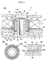
- Fig. 13 (a) is a longitudinal sectional view showing essential parts of a tape drive unit in a refill type coat film transfer tool in embodiment 7 of the invention.
- Fig. 13 (b) is a perspective view showing a second engaging portion of a clutch mechanism as the essential part.
- Fig. 14 (a) is a longitudinal sectional view showing a clutch mechanism in a tape drive unit in a refill type coat film transfer tool in embodiment 8 of the invention.
- Fig. 14 (b) is a perspective view showing a first engaging portion of the clutch mechanism.
- Fig. 15 (a) is a longitudinal sectional view showing a clutch mechanism in a tape drive unit in a refill type coat film transfer tool in embodiment 9 of the invention.
- Fig. 15 (b) is a perspective view showing a first engaging portion of the clutch mechanism.
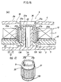
- Fig. 16 (a) is a longitudinal sectional view showing a disposable type coat film transfer tool in embodiment 10 of the invention.
- Fig. 16 (b) is a magnified longitudinal sectional view of a clutch mechanism of the coat film transfer tool.
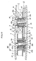
- Fig. 17 is a longitudinal sectional view showing a refill type coat film transfer tool in embodiment 11 of the invention.
- Fig. 18 is a perspective exploded view of the coat film transfer tool.
- Fig. 19 is a longitudinal sectional view showing a disposable type coat film transfer tool in embodiment 12 of the invention.
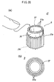
- Fig. 20 (a) is a perspective view corresponding to Fig. 6 (a) showing a modified example of rewinding operation unit in the tape drive unit.
- Fig. 20 (b) is a plan view corresponding to Fig. 6 (b) showing the rewinding operation unit.
- Fig. 21 (a) is a partially cut-away perspective view of a conventional coat film transfer tool.
- Fig. 21 (b) is a longitudinal sectional view showing an internal structure of the coat film transfer tool.
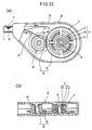
- Fig. 22 (a) is a partially cut-away perspective view of other conventional coat film transfer tool.
- Fig. 22 (b) is a longitudinal sectional view showing an internal structure of the coat film transfer tool.
- Fig. 1 through Fig. 20 show film transfer tools according to the invention, and throughout the drawings the same reference numerals refer to same structual members or elements.
- a coat film transfer tool according to the invention is shown in Fig. 1 through Fig. 7.
- This coat film transfer tool 1 is specifically used as an erasing tool for correcting a wrong letter or the like, and comprises essential parts, including a tape drive unit D, a replaceable tape cartridge C, and a coat film transfer head H, provided in a case 2 to be held and manipulated by one hand.
- the case 2 is a plastic flat box formed by injection molding or the like.
- the case 2 has the front contour shape and dimensions enough to incorporate the tape drive unit D and tape cartridge C, and can be decomposed into a case main body 3 and a cover body 4, and the structual parts D, C, and H are provided in the case main body 3.
- Flat face and back sides 2a, 2b of the case 2 form gripping surfaces to be held and manipulated by hand as shown in Fig. 7.
- an operation hole 38 for rewinding operation is opened in the cover body 4.
- the tape drive unit D mainly comprises, as shown in Fig. 2, Fig. 3, and Fig. 5, a feed rotary unit 5 for rotating and driving a feed reel 10, a take-up rotary unit 6 for rotating and driving a take-up reel 11, an interlock mechanism 7 for interlocking these rotary units 5, 6, a clutch mechanism 8, and a tape rewinding mechanism 9.
- the feed rotary unit 5 comprises a drive side rotary gear 20 for composing the interlock mechanism 7, and a driven member 21 for composing a tape winding portion 12 of the feed reel 10.
- This driven member 21 composes the essential parts of the clutch mechanism 8 and tape rewinding mechanism 9 as described later.
- a hollow rotary shaft 20a of the drive side rotary gear 20 is rotatably supported on a hollow support shaft 22 provided upright on the inner side of the case main body 3.
- a catch 22a for preventing the rotary shaft 20a from slipping out is provided.
- the driven member 21 is a hollow cylinder, and is rotatably provided on the rotary shaft 20a of the drive side rotary gear 20, and a tooth profile engaging portion 21a such as serration or spline is formed on its outer circumference as shown in the drawing.
- a catch 20b for preventing the driven member 21 from slipping out is provided.
- the take-up rotary unit 6 comprises a follower side rotary gear 23 for composing the interlock mechanism 7, and a hollow rotary shaft 23a of the rotary gear 23 is rotatably supported on a hollow support shaft 24 provided upright on the inner side of the case main body 3.
- a catch 24a for preventing the rotary shaft 20a from slipping out is provided.
- a tooth profile engaging portion 25 such as serration or spline is formed on the outer circumference of the rotary shaft 23a.
- the interlock mechanism 7 is composed of the drive side rotary gear 20 and follower side rotary gear 23, and they are engaged with each other at a specific gear ratio.
- the take-up rotary unit 6 is rotated in cooperation with the feed rotary unit 5 always at a specific rotation ratio.
- This rotation ratio that is, the gear ratio of the both gears 20, 23 is set properly so that the coat film transfer tape T may be delivered and taken up smoothly, in consideration of the winding diameter of the coat film transfer tape T at the feed reel 10 and take-up reel 11 as mentioned later.
- the clutch mechanism 8 is to synchronize the feed speed and take-up speed of the coat film transfer tape T in the feed reel 10 and take-up reel 11 described later, and is provided in the feed rotary unit 5.
- FIG. 4 A specific constitution of the clutch mechanism 8 is shown in Fig. 4, which comprises, as a principal part, an elastomer O-ring (friction member) 30 interposed between the drive side rotary gear 20 and the driven member 21.
- This O-ring 30 composes a power transmission unit (power transmission means) between the drive side rotary gear 20 as the rotary drive unit, and the driven member 21 which is the tape winding portion 12, and is made of silicone rubber having a circular section (see Fig. 4 (b)).
- the O-ring 30 is repulsively interposed between the confronting axial ends of the both members 20, 21, and these three members contact with each other in frictional engagement state.
- a recess 31 having a flat engaging plane 31a is formed on the outer circumference of the rotary shaft 20a in the drive side rotary gear 20, and the lower end of the driven member 21 also a flat engaging plane 21b, and the O-ring 30 is repulsively engaged by friction with these engaging planes 31a, 21b.
- power transmission of the clutch mechanism 8 makes use of frictional force due to thrust load acting between the engaging planes 31a, 21b, and this frictional force is set at an optimum value by properly adjusting mainly the distance between the engaging planes 31a, 21b, and the sectional diameter of the O-ring 30.
- a position defining unit 32 may be provided in the recess 31 (see double dot chain line in Fig. 4 (a)), and the distance between the engaging planes 31a, 21b may be defined within a specific value.
- the clutch mechanism 8 may function always with a stable frictional force.
- the driven member 21 serves also as the operation unit of the tape rewinding mechanism 9 described later, there is a possibility of application of excessive thrust load to the O-ring 30, and hence it is preferred to form such position defining unit 32.
- the inner and outer diameters of the O-ring 30 are set properly within a range allowing the O-ring 30 to be passed through the rotary shaft 20a in the drive side rotary gear 20, and to contact with the both engaging planes 31a, 21b. Therefore, for example, by setting the inner diameter of the O-ring 30 slightly larger than the outer diameter of the rotary shaft 20a, the O-ring 30 can be incorporated into the outer circumference of the rotary shaft 20a, that is, the recess 31, easily and smoothly.
- a reverse rotation preventive mechanism 35 to prevent reverse rotation of the reels 10, 11 is provided in the take-up rotary unit 6.
- This reverse rotation preventive mechanism 35 is composed of a detent pawl 35a provided in the follower side rotary gear 23, and multiple reverse rotation preventive pawls 35b, 35b, ... provided on the inner side of the case main body 3 annularly and concentrically with the hollow support shaft 24. Accordingly, if the both reels 10, 11 rotate in the arrow direction, the detent pawl 35a rides over while elastically deforming the reverse rotation preventive pawls 35b, 35b, ..., thereby allowing this normal rotation.
- the detent pawl 35a is engaged with any one of the reverse rotation preventive pawls 35b, 35b, ..., and blocks the reverse rotation.
- the reverse rotation preventive mechanism 35 may be provided in the drive side rotary gear 20.
- the tape rewinding mechanism 9 is designed to eliminate and remove the slack of the coat film transfer tape T between the feed reel 10 and take-up reel 11, and is provided in the tape winding portion 12 of the feed reel 10.
- the tape rewinding mechanism 9 comprises the hollow cylindrical driven member 21 as principal constituent part as mentioned above, and a top end 36 of the driven member 21 is extended, and a rewinding operation unit 37 is integrally formed in the hollow edge.
- the rewinding operation unit 37 faces to the outside of the case 2 through the operation hole 38 formed in the cover body 4 of the case 2.
- the rewinding operation unit 37 is set so as to be flush with or lower than the surface of the case 2, or the gripping surface 2a (see Fig. 4 (a)).
- the rewinding operation unit 37 is formed in an operation groove, and a plate-shaped operation member 39 such as a coin may be engaged with this operation groove 37.
- the operation groove 37 is formed of a pair of grooves 37a, 37a provided at edges on one straight line in the top end 36.
- the depth of the grooves 37a, 37a is set in a range so as to be engaged with the operation member 39, in consideration of the height position of the top end portion of the rotary shaft 20a.
- the number of operation grooves 37 may be properly increased.
- the hollow support shaft 22 is concealed by the top end portion of the rotary shaft 20a so as not to be visible from outside.
- the inner circumference of the operation hole 38 of the cover body 4 is formed in a taper form as shown in Fig. 4 (a), and it is designed to engage and operate the operation member, for example, the coin 39 from outside of the case 2 into the operation groove 37.
- the tape cartridge C is a replaceable constituent member as a consumable part, and its specific structure is shown in Fig. 2, Fig. 3, and Fig. 5.
- the feed reel 10 and take-up reel 11 are rotatably provided on a supporting base plate 40 made of a thin plate material, and the tape cartridge C is detachably mounted on the tape drive unit D of the case main body 3 as shown in Fig. 2 and Fig. 3.
- the feed reel 10 and take-up reel 11 are provided with hollow drums 45, 46 for winding the coat film transfer tape T.
- drums 45, 46 have their support ends rotatably supported on the support base plate 40.
- tooth profile engaging portions 45a, 46a such as serration or spline are formed, respectively corresponding to the tooth profile engaging portion 21a of the driven member 21 and the tooth profile engaging portion 25 of the rotary shaft 23a of the follower side rotary gear 23.
- the drum 45 of the feed reel 10 is detachably engaged and supported on the driven member 21 through these tooth profile engaging portions 45a, 21a, and are hence integrated with the driven member 21 in the rotating direction to form the tape winding portion 12.
- the hollow drum 46 of the take-up reel 11 is detachably engaged and supported on the rotary shaft 23a through the tooth profile engaging portions 46a, 25, and mounted integrally and rotatably with the rotary shaft 23a.
- the coat film transfer tape T On the outer circumference of the drum 45 of the feed reel 10, the coat film transfer tape T is wound, and the feeding side leading end is connected to the outer circumference of the drum 46 of the take-up reel 11.
- a film base material such as polyester film, acetate film, other plastics, or paper
- a releasing agent layer such as vinyl chloride-vinyl acetate copolymer resin or low molecular weight polyethylene is formed, and a white corrective paint layer is formed thereon, and further an adhesive agent (pressure sensitive adhesive) layer such as polyurethane having a pressure-sensitive adhesion is formed thereon (specific structure is not shown).
- an adhesive agent (pressure sensitive adhesive) layer such as polyurethane having a pressure-sensitive adhesion is formed thereon (specific structure is not shown).
- the corrective paint layer so-called dry type is used so as to be able to write thereon immediately after transfer.
- the free end of the drum 45 of the feed reel 10 is an open end as it is, and a tape running guide flange 47 is provided at the free end of the drum 46 of the take-up reel 11.
- the layout of the reels 10, 11 on the support base plate 40 is as shown in Fig. 2, in which the drums 45, 46 are set so as to be positioned coaxially with respect to the feed rotary unit 5 and take-up rotary unit 6 of the tape drive unit D.
- a pair of guide pins 48, 49 for guiding the coat film transfer tape T are provided upright and integrally.
- One guide pin 48 is for guiding the coat film transfer tape T being paid out from the feed reel 10
- the other guide pin 49 is for guiding the coat film transfer tape T' being taken up on the take-up reel 11, and a flanged guide roller 49a is rotatably supported on the guide pin 49.
- the reels 10, 11 are engaged with the both rotary units 5, 6 of the tape drive unit D respectively from above, and the support base plate 40 is mounted on these rotary units 5, 6.
- the both reels 10, 11 are instantly set detachably and integrally rotatably in the both rotary units 5, 6.
- the both reels 10, 11 can be instantly detached easily from the both rotary units 5, 6.
- the coat film transfer head H is for pressing the coat film transfer tape T on the correction area (object of transfer) such as wrong letter on a sheet of paper, and it is rotatably fitted on a cylindrical front end 50 of the case 2.
- the cylindrical leading end 50 is composed by assembly of cylindrical halves of the case main body 3 and cover body 4.
- the head H is made of plastics having a certain elasticity.
- the leading or front end portion of the head H is a thin plate slightly wider than the coat film transfer tape T as shown in Fig. 1, and is formed in a taper section to be gradually thinner toward the leading end, and the leading end Ha of the head H is the pressing portion for pressing the coat film transfer tape T.
- guide flanges Hb, Hb for guiding running of the coat film transfer tape T are formed.
- the base end portion of the head H is semicylindrical having a semicircular section, and is rotatably supported on the cylindrical front end 50 of the case 2.
- Reference numeral 51 denotes an arc-shaped flange for positioning in the axial direction provided at the base end of the head H, and this flange 51 is rotatably fitted to an annular groove 52 of the cylindrical front end 50.
- the coat film transfer tape T is paid out from the feed reel 10, as shown in Fig. 1 (b), and is inverted through the pressing portion Ha of the head H through the guide pin 48, and is further wound around the take-up reel 11 through the guide pin 49.
- the head H is selectively positioned at the shown application position (laterally pulling position), and the orthogonal coat film transfer tape exchange position (also vertically pulling position).
- the pressing portion Ha of the head H guides the coat film transfer tape T so that the coat film transfer tape T may be nearly opposite to the gripping surfaces 2a, 2b of the case 2,that is, the face and back sides of the coat film transfer tape T may be directed nearly in the same direction to the gripping surfaces 2a, 2b (that is, nearly parallel to each other).
- the pressing portion Ha of the head H guides the coat film transfer tape T so that the coat film transfer tape T may remain in the winding position of the feed reel 10 and take-up reel 11, that is, the face and back sides of the coat film transfer tape T may be directed nearly in opposite direction to the gripping surfaces 2a, 2b (that is, nearly orthogonal to each other).
- coat film transfer tool 1 by the pressing operation of the coat film transfer head H as mentioned later, a tensile force applied to the coat film transfer tape T (arrow A direction in Fig. 1) acts on the feed reel 10 as torque, the drive side rotary gear 20 is rotated through the tape winding portion 12 of the feed reel 10, and further through the clutch mechanism 8. This torque rotates the follower side rotary gear 23 and further the take-up reel 11 in cooperation through the interlock mechanism 7, so that the coat film transfer tape T' after use is taken up automatically by the take-up reel 11.
- the rotation ratio of the drive side rotary gear 20 and follower side rotary gear 23 (corresponding to the gear ratio of the interlock mechanism 7) is always constant, whereas the ratio of the outer diameter of the coat film transfer tape T in the feed reel 10 and the outer diameter of the coat film transfer tape T' in the take-up reel 11 varies with the passing of time and is not constant. That is, as being used, the outer diameter of the coat film transfer tape T in the feed reel 10 becomes gradually smaller, while the outer diameter of the coat film transfer tape T' in the take-up reel 11 gradually increases to the contrary.
- the take-up speed of the take-up reel 11 is gradually increased in comparison with the feed speed of the feed reel 10, and the synchronism of the two speed is broken, and the torque acting on the feed reel 10 gradually increases.
- this torque overcomes the frictional force of the clutch mechanism 8, and the tape winding portion 12 slides and rotates against the drive side rotary gear 20, and the torque difference between the both reels 10, 11 is eliminated, and the feed speed is synchronized with the take-up speed, so that smooth running of the coat film transfer tape T is assured.
- power transmission in the clutch mechanism 8 makes use of the frictional force by the thrust load between the tape winding portion 12 and the drive side rotary gear 20, and in the construction of the clutch mechanism 8, the frictional force can be set to an optimum value by properly adjusting the relative dimensions in the thrust direction among the constituent members 20, 21, 30.
- the operation groove 37 of the tape rewinding mechanism 9 is rotated and manipulated in the rewinding direction from outside of the case 2 (rotating in the direction of arrow B in Fig. 1 (b)), and thereby the slack of the coat film transfer tape T is eliminated and removed.
- the coat film transfer tool 1 of the embodiment by selectively positioning the head H at either laterally pulling position or vertically pulling position, it is usable in both lateral pull suited to correction of part of sentence written laterally as in European language, and in vertical pull suited to correction of part of sentence written vertically as in Japanese language.
- the gripping surfaces 2a, 2b of the case 2 are held like a writing tool.
- the pressing portion Ha of the head H is fitted to the starting end (left end) of the correction area (object of transfer) on the paper to correct a wrong letter or the like, and is directly moved laterally, that is, in the right direction on the paper and stopped at the terminal end (right end) of the correction area 60.
- the corrective paint layer (white) of the coat film transfer tape T in the pressing portion Ha of the head H is peeled off from the film base material, and is transferred and applied on the correction area 60.
- the wrong letter is concealed, and a correct letter can be immediately written over.
- the engaging plane 21b of the driven member 21 is formed so as to surround the O-ring 30 as shown in a magnified sectional view in Fig. 6 (b). That is, the engaging plane 21b is composed of an annular flat surface 70a frictionally engaged with the upper surface of the O-ring 30 opposite parallel to the engaging plane 31a of the drive side rotary gear 20, and a cylindrical inner circumference 70b frictionally engaged with the outer side of the O-ring 30 opposite to the rotary shaft outer circumference 71 of the drive side rotary gear 20.
- both the frictional force by thrust load acting between the annular flat surface 70a and engaging plane 31a, and the frictional force by radial load acting between the cylindrical inner circumference 70b and rotary shaft outer circumference 71 are utilized.
- power transmission of the clutch mechanism 68 is mainly based on the frictional force by thrust load, and the frictional force by radial load is only supplementary for adjusting the transmission force, so that fine adjustment of pressure is enabled.
- a lower end portion 72 for forming the cylindrical inner circumference 70b of the driven member 21 functions, same as the position defining portion 32 in embodiment 1, as the position defining portion for suppressing the distance between the annular flat surface 70a and the engaging plane 31a within a set value, and hence prevents the O-ring 30 from being compressed and deformed excessively in the vertical direction.
- a plastic friction sheet 80 is used as a friction member interposed between the engaging plane 21b of the driven member 21 and the engaging plane 31a of the drive side rotary gear 20.
- This friction sheet 80 is a thin wall plate material formed in an annular form as shown in Fig. 9 (b), and its upper and lower flat surfaces are frictionally engaged respectively with the engaging planes 31a, 21b.
- the inner and outer diameters and thickness of the annular friction sheet 80 are set in the same conditions as the inner and outer diameters and sectional diameter of the O-ring 30 in embodiment 1.
- a first engaging portion 89 and a second engaging portion 90 are respectively formed, and these engaging portions 89, 90 are engaged frictionally.
- These engaging portions 89, 90 are composed of plural annular ribs 89a, 90a provided concentrically with the driven member 21 and drive side rotary gear 20.
- These annular ribs 89a, 90a have both angle sections consisting of a pair of slopes as shown in Fig. 10 (c), and the diameters of these confronting annular ribs 89a, 90a are set slightly different from each other. Consequently, these annular ribs 89a, 90a are composed so that the slopes on one side may contact frictionally with each other as shown in Fig. 10 (c).
- the frictional force of the clutch mechanism 88 can be adjusted by increasing or decreasing the contact area of the annular ribs 89a, 90a or the contacting force, and in this case, the frictional coefficient of the constituent materials of the driven member 21 and drive side rotary gear 20 (for example, ABS (acrylonitrile-butadiene-styrene) resin, etc.) is also taken into consideration.
- ABS acrylonitrile-butadiene-styrene
- the number of parts is decreased, and it is suited to mass production, so that the manufacturin cost and product cost may be curtailed.
- afirst engaging portion 99 of the driven member 21 is formed on a flat plane
- a second engaging portion 100 of the drive side rotary gear 20 is composed of plural annular ribs 100a (see Fig. 11 (b)) same as the second engaging portion 90 of embodiment 4 (see Fig. 10).
- the flat plane 99 and the leading ends of the annular ribs 100a, 100a, ... are formed to contact with each other frictionally (see Fig. 11 (c)).
- the frictional force of the clutch mechanism 98 can be adjusted by increasing or decreasing the height of the annular ribs 100a.
- the engaging portions 99, 100 may be formed in reverse composition of the composition shown in Fig. 11, that is, the first engaging portion 99 may be composed of plural annular ribs, and the second engaging portion 100 may be formed on a flat plane.
- a first engaging portion 109 of the driven member 21 is formed on a flat plane
- a second engaging portion 110 of the drive side rotary gear 20 is composed of multiple radial ribs 110a (see Fig.12 (b)), formed at equal intervals in the circumferential direction, concentrically with the drive side rotary gear 20.
- the flat plane 109 and the leading ends of the radial ribs 110a, 110a, ... are formed to contact with each other frictionally (see Fig. 12 (c)).
- the frictional force of the clutch mechanism 108 can be adjusted by increasing or decreasing the height of the radial ribs 110a.
- the engaging portions 109, 110 may be formed in reverse composition of the composition shown in Fig. 12, that is, the first engaging portion 109 may be composed of multiple radial ribs, and the second engaging portion 110 may be formed on a flat plane.
- a first engaging portion 119 of the driven member 21 is formed on a flat plane, and a second engaging portion 120 of the drive side rotary gear 20 is composed of plural (four in this drawing) engaging protrusions 120a having elasticity in the axial direction, that is, the vertical direction.
- the engaging protrusions 120a are, more specifically, formed as being extended outward in the radial direction from the outer circumference of the rotary shaft 20a of the drive shaft rotary gear 20 as shown in Fig. 13 (b), and the engaging protrusions 120a are disposed at equal intervals in the circumferential direction on the outer circumference of the rotary shaft 20a.
- the rotary shaft 20a and the outer circumference of the drive side rotary gear 20 are coupled by plural (four in this drawing) coupling members 121 disposed between engaging protrusions 120a, 120a.
- the flat plane 109 and the leading ends of the engaging protrusions 120a, 120a, ... are formed to contact with each other frictionally (see Fig. 13 (a)).
- the frictional force of the clutch mechanism 118 can be adjusted by increasing or decreasing the elastic force applied to the engaging protrusions 120a, or increasing or decreasing the number of engaging protrusions 120a.
- a first engaging portion 129 of the driven member 21 is composed of plural engaging protrusions 129a having elasticity in the axial direction, and a second engaging portion 130 of the drive side rotary gear 20 is formed on a flat plane.
- the engaging protrusions 129a are specifically formed by projecting radially downward from the lower end outer peripheral edge of the driven member 21, and are disposed at equal intervals on the whole circumference in the circumferential direction at the lower end outer peripheral edge of the driven member 21.
- the leading ends of the engaging protrusions 129a and the flat plane 130 are formed to contact with each other frictionally, and the frictional force of the clutch mechanism 128 can be adjusted by increasing or decreasing the elastic force applied to the engaging protrusions 129a, or increasing or decreasing the number of engaging protrusions 129a.
- a first engaging portion 139 of the driven member 21 is an annular engaging flange having elasticity in the axial direction, or the vertical direction, and a second engaging portion 140 of the drive side rotary gear 20 is formed on a flat plane.
- the engaging flange 139 is specifically in a form of conical flange having a sectional shape projecting radially downward from the lower end outer peripheral edge of the driven member 21.
- the leading end of the engaging flange 139 and the flat plane 140 are formed to contact with each other frictionally, and the frictional force of the clutch mechanism 138 can be adjusted by varying the projection length or inclination angle of the engaging flange 139.
- FIG. 16 This embodiment is shown in Fig. 16, relating to a disposable type for discarding the coat film transfer tape T when used up, as compared with the refill type illustrated in embodiments 1 to 9.
- the feed reel 10 and take-up reel 10 are rotatably provided in the case 2 respectively, and these reels 10, 11 are provided with automatic winding mechanism.
- the tape winding portion 12 of the feed reel 10 was separated into the driven member 21 and drum 45, whereas they are formed integrally in this embodiment, and the tape winding portion 12 is rotatably provided on the rotary shaft 20a of the drive side rotary gear 20.
- a tape running guide flange 150 is integrally provided at the support end side of the tape winding portion 12. This guide flange 150 is designed to slide on the upper surface of the drive side rotary gear 20, and functions as a position defining unit for suppressing the distance between both engaging planes 31a, 21b of the clutch mechanism 8 within a set value.
- a tape running guide flange 151 is also formed integrally, and this guide flange 151 is designed to slide on the upper surface of the drive side rotary gear 20.
- the coat film transfer head H may be provided either rotatably about the axial center or stationarily, at the cylindrical leading end 50 of the case 2.
- the mounting angle of the coat film transfer head H in the rotating direction may be variable depending on the purpose, that is, in the lateral pulling position as shown in Fig. 1 and Fig. 7 in the case of the coat film transfer tool 1 for lateral pulling use, or in the vertical pulling position, orthogonal to the lateral pulling position, in the case of coat film transfer tool 1 for vertical pulling use.
- This embodiment is shown in Fig. 17 and Fig. 18, relating to a double clutch type installing another clutch mechanism 158 at the take-up rotary unit 6, in the constitution of the coat film transfer tool of embodiment 1.
- this clutch mechanism 158 is same as that of the clutch mechanism 8 of the feed rotary unit 5. That is, a driven member 159 is interposed between the rotary shaft 23a of the follower side rotary gear 23 and the drum 46 of the take-up reel 11, and a tape winding portion 160 of the take-up reel 11 is composed by this driven member 159 and drum 46.
- the mutual coupling structure of the rotary shaft 23a, driven member 159 and drum 46 is same as in the clutch mechanism 8, and an O-ring 161 is interposed as friction member between the engaging planes 159a, 23b of the driven member 159 and follower side rotary gear 23.
- the other specific construction corresponds to the clutch mechanism 8.
- the drum 45 rotates in the rewinding direction, and the drum 46 is in stopped state by the action of the reverse rotation preventive mechanism 35, so that the slack of the coat film transfer tape T between the both reels 10, 11 is eliminated and removed.
- a tape winding portion 160 of the take-up reel 11 is integrated as shown, and the tape winding portion 160 is rotatably provided on the rotary shaft 23a of the follower side rotary gear 23.
- a tape running guide flange 151 is integrally provided at the support end side of the tape winding portion 160. This guide flange 151 slides on the upper surfaces of the follower side rotary gear 23, and function as a position defining unit for suppressing the distance between two engaging planes 159a, 23b of the clutch mechanism 158 within a set value.
- the driven member 21 or tape winding portion 12 is in a hollow cylindrical form, and rewinding operation units 37, 57 are provided in the hollow edge, but the free end of the driven member 21 or tape rewinding portion 12 may be closed, and the rewinding operation units 37,57 may be provided at this closed end.
- the closed end of the driven member 21 or tape winding portion 12 the rotary shaft 20a and hollow support shaft 22 are concealed from outside, so that a simple appearance may be presented.
- the rewinding operation unit 57 as shown in Fig. 20 may be employed. That is, the rewinding operation unit 57 has an anti-skid shape that can be manipulated by finger or the like, and specifically it is composed of anti-skid undulations 57a, 57a, ... such as tread pattern.
- the clutch mechanism for synchronizing the feed speed and take-up speed of the coat film transfer tape at the feed reel and take-up reel composes the power transmission unit between the tape winding portion for winding the coat film transfer tape and the rotary drive unit for rotating and driving the tape winding portion, at least in one of the both reels, and the power transmission of this power transmission unit makes use of the frictional force due to thrust load between the tape winding portion and the rotary drive unit, and therefore each constituent member slides smoothly and relatively in synchronizing action, and the sense of manipulation is excellent and uneven running does not occur.
- the construction of the clutch mechanism may be determined by properly adjusting the dimensional relation in the thrust direction among mutual constituent members, and the frictional force may be set to an optimum value, and as compared with the conventional structure making use of frictional force due to radial load (see Fig. 22), the designing and manufacturing conditions of constituent members are less strict and the manufacture is easy, assembling is easy, and hence the manufacturing cost and device cost may be also lowered.
Abstract
Description
- The present invention relates to a clutch mechanism of a coat film transfer tool, and a coat film transfer tool comprising this clutch mechanism, and more particularly to a clutch technology for synchronizing the feed speed and take-up speed of coat film transfer tape in a feed reel and a take-up reel, in a coat film transfer tool for transferring a coat film such as corrective paint layer, adhesive layer or the like on a coat film transfer tape onto a sheet of paper or the like, and automatically collecting the coat film transfer tape after use.
- An example of structure of this kind of coat film transfer tool is shown in Fig. 21, and in this transfer tool, in a case (a) that can be held and manipulated by a single hand, a feed reel (c) with a coat film transfer tape (b) wound thereabout and a take-up reel (d) for collecting the coat film transfer tape (b') after use are rotatably provided, and a coat film transfer head (f) for pressing the coat film transfer tape (b) onto the object of transfer is protruding at the front end of the case (a). The both reels (c) and (d) are wound up automatically as being linked by an interlock mechanism (g) so as to cooperate with each other. In this interlock mechanism (g), gears (h) and (i) provided on the outer circumference of the both reels (c) and (d) are engaged with each other.
- When this coat film transfer tool is used as an erasing tool for correcting a wrong letter or the like, the case (a) is held by one hand, and moved in a desired direction while pressing the coat film transfer tape (b) tightly to the correction area (the object of transfer) by a pressing portion (j) of the head (f). As a result, the corrective paint layer of the coat film transfer tape (b) in the pressing portion (j) of the head (f) is applied on the correction area, and the letter is deleted, and the coat film transfer tape (b') after use is automatically wound up and collected by the take-up reel (d).
- In this case, as being used, the outer diameter of the coat film transfer tape (b) on the feed reel (c) becomes smaller, while the outer diameter of the coat film transfer tape (b') on the take-up reel (d) becomes larger. On the other hand, the rotation ratio of the feed reel (c) and take-up reel (d) (corresponding to the gear ratio of the interlock mechanism (g)) is always constant.
- Accordingly, the take-up speed of the take-up reel (d) tends to be faster gradually as compared with the feed speed of the feed reel (c), and to prevent this, therefore, it is necessary to synchronize the feed speed and take-up speed. For this purpose, the feed reel (c) is provided with a clutch mechanism (k) for synchronizing the feed speed and take-up speed.
- That is, in the feed reel (c), a boss (m) of a drive gear (h) rotatably supported on a support shaft (n), and a tape feed core (o) with the coat film transfer tape (b) wound thereabout is rotatably fitted on the boss (m), and the clutch mechanism (k) is provided between the boss (m) and the tape feed core (o).
- In this clutch mechanism (k), elastically deforming clutch pawls (p), (p) provided on the outer circumference of the boss (m) are engaged with multiple stopping portions (q), (q), ... provided in the inner circumference of the tape feed core (o), elastically.
- As the take-up speed is gradually increased as compared with the feed speed, and the synchronism of the two speeds is broken to increase the torque acting on the tape feed core (o), the clutch mechanism (k) causes the tape feed core (o) to slide and rotate on the boss (m), so that the feed speed is synchronized with the take-up speed.
- In such clutch mechanism (k), the engaging and disengaging action of the clutch pawls (p), (p) and stopping portions (q), (q), ... is intermittently repeated elastically with a clicking sound, the manipulating hand of the user may feel discomfort, and running of the coat film transfer tape (b) may be uneven, and as the use is continued further, the engaging and disengaging action becomes more frequent as the revolution speed of the tape feed core (o) increases, and the discomfort and uneven running become more obvious, and further improvements were demanded.
- Concerning this point, the present inventors already proposed a clutch mechanism (r) as shown in Fig. 22 (see, for example, Japanese Laid-open Patent No. 5-58097). In this clutch mechanism (r), a circular elastic friction member (s) such as O-ring is interposed between the cylindrical outer circumference of the boss (m) and the cylindrical inner circumference of the tape feed core (o) in a frictionally engaged state.
- According to this clutch mechanism (r), in the synchronizing action, the three members (m), (s), and (o) relatively slide smoothly, and hence the discomfort and uneven running due to such elastic and intermittent repeating action have been eliminated.
- In the structure of this clutch mechanism (r), however, since the transmission of power is to make use of the frictional force by radial load among the three members (m), (s), and (o), the design and manufacture conditions of the friction member (s) are very strict, and it is hard to manufacture, which was a bottleneck for reducing the manufacturing cost.
- That is, if the frictional force is too strong, the sense of manipulation tends to be too heavy in the later phase of use. On the other hand, if the frictional force is too weak, the sense of manipulation tends to be too light in the initial phase of use. Hence, considering their relation, the frictional force must be set at an optimum value.
- To obtain the optimum value of frictional force, therefore, in design and manufacture of the friction member (s), it is required to match its inner diameter and outer diameter respectively with the cylindrical outer diameter of the boss (m) and the cylindrical inner diameter of the tape feed core (o), but since the friction member (s) itself is also elastic, its thickness in the radial direction or its sectional diameter must be also taken into consideration. It hence requires an additional process for fine adjustment of the shape and dimensions of the friction member (s) after assembling the clutch mechanism (r).
- Still more, since the radial dimensions and other conditions of the friction member (s) are set strictly, to assemble the friction member (s) between the cylindrical outer circumference of the boss (m) and the cylindrical inner circumference of the tape feed core (o), it was needed to put in by force, and the assembling work was difficult.
- It is hence a primary object of the invention to present a novel clutch mechanism of a coat film transfer tool solving the problems in the prior art.
- It is other object of the invention to present a clutch mechanism having an inexpensive structure easy to manufacture, by making use of a frictional force by thrust load, in a coat film transfer tool of automatic winding type.
- It is other object of the invention to present a coat film transfer tool of automatic winding type comprising such clutch mechanism.
- The clutch mechanism of the invention is for use in a coat film transfer tool of automatic winding type comprising a feed reel with a coat film transfer tape wound thereabout and a take-up reel for collecting the coat film transfer tape after use, rotatably provided in a case that can be held and manipulated by one hand, in which thetake-up reel cooperates with the feed reel, for synchronizing the feed speed and take-up speed of the coat film transfer tape in both reels, wherein power transmission means between a tape winding portion for winding up the coat film transfer tape and a rotary drive unit for rotating and driving this tape winding portion is composed in at least one of the two reels, and power transmission of the power transmission means makes use of the frictional force by the thrust load between the tape winding portion and the rotary drive unit, and is connected and disconnected by the difference in torque between these two members.
- The coat film transfer tool of the invention comprises a case having shape and dimensions to be held and manipulated by one hand, a feed reel rotatably provided in the case and winding a coat film transfer tape, a take-up reel rotatably provided in the case for collecting the coat film transfer tape after use, an interlock mechanism for linking these two reels so as to cooperate with each other, and a coat film transfer head protruding at the front end of the case for pressing the coat film transfer tape onto the object of transfer, further comprising said clutch mechanism at least in one of the two reels.
- The coat film transfer tool comprising the clutch mechanism is classified into the disposable type to be discarded when the coat film transfer tape is used up, and the refill type that can be used repeatedly only by replacing the spent coat film transfer tape with a new one.
- In the coat film transfer tool comprising the clutch mechanism of the invention as power transmission means, the take-up speed of the take-up reel gradually becomes faster as compared with the feed speed of the feed reel, and their synchronism is broken to increase the torque acting on the tape winding portion for winding the coat film transfer tape, and herein the clutch mechanism acts to cause the tape winding portion to slide and rotate on the rotary drive unit to eliminate the torque difference between the two, so that the feed speed is synchronized with the take-up speed.
- In this case, the power transmission in the clutch mechanism makes use of the frictional force by thrust load between the tape winding portion and the rotary drive unit, and therefore the structual components relatively slide smoothly in this synchronizing action.
- In the structure of the clutch mechanism, by properly adjusting the dimensional relation in the thrust direction between the mutual structual components, the frictional force can be set at an optimum value.
- These and other objects and features of the invention will be better appreciated by reading the detailed description based on the accompanying drawings and novel facts indicated in the claims.
- Fig. 1 (a) is a front view showing the appearance of a coat film transfer type of refill type in
embodiment 1 of the invention. - Fig. 1 (b) is a front view showing the internal structure of the coat film transfer tool by removing the cover body.
- Fig. 2 is a longitudinal sectional view showing an essential structure of the coat film transfer tool.
- Fig. 3 is a longitudinal view showing a disassembled state of the essential structure of the coat film transfer tool.
- Fig. 4 (a) is a magnified longitudinal sectional view showing the engaging state of a clutch mechanism which is an essential part in a tape drive unit of the coat film transfer tool.
- Fig. 4 (b) is a perspective view showing an O-ring in the clutch mechanism.
- Fig. 5 is a perspective exploded view of the coat film transfer tool.
- Fig. 6 (a) is a perspective view showing a rewinding operation unit in the tape drive unit.
- Fig. 6 (b) is a plan view showing the rewinding operation unit.
- Fig. 7 is a perspective view showing the operating state of the coat film transfer tool.
- Fig. 8 (a) is a longitudinal sectional view showing essential parts of a tape drive unit in a refill type coat film transfer tool in
embodiment 2 of the invention. - Fig. 8 (b) is a magnified longitudinal sectional view of a clutch mechanism as the essential part.
- Fig. 9 (a) is a longitudinal sectional view showing essential parts of a tape drive unit in a refill type coat film transfer tool in
embodiment 3 of the invention. - Fig. 9 (b) is a perspective view showing a sheet of a clutch mechanism as the essential part.
- Fig. 10 (a) is a longitudinal sectional view showing essential parts of a tape drive unit in a refill type coat film transfer tool in
embodiment 4 of the invention. - Fig. 10 (b) is a plan view showing a second engaging portion of a clutch mechanism as the essential part.
- Fig. 10 (c) is a magnified longitudinal sectional view showing the engaging state of first and second engaging portions of the clutch mechanism.
- Fig. 11 (a) is a longitudinal sectional view showing essential parts of a tape drive unit in a refill type coat film transfer tool in
embodiment 5 of the invention. - Fig. 11 (b) is a plan view showing a second engaging portion of a clutch mechanism as the essential part.
- Fig. 11 (c) is a magnified longitudinal sectional view showing the engaging state of first and second engaging portions of the clutch mechanism.
- Fig. 12 (a) is a longitudinal sectional view showing essential parts of a tape drive unit in a refill type coat film transfer tool in
embodiment 6 of the invention. - Fig. 12 (b) is a plan view showing a second engaging portion of a clutch mechanism as the essential part.
- Fig. 12 (c) is a magnified longitudinal sectional view showing the engaging state of first and second engaging portions of the clutch mechanism.
- Fig. 13 (a) is a longitudinal sectional view showing essential parts of a tape drive unit in a refill type coat film transfer tool in
embodiment 7 of the invention. - Fig. 13 (b) is a perspective view showing a second engaging portion of a clutch mechanism as the essential part.
- Fig. 14 (a) is a longitudinal sectional view showing a clutch mechanism in a tape drive unit in a refill type coat film transfer tool in
embodiment 8 of the invention. - Fig. 14 (b) is a perspective view showing a first engaging portion of the clutch mechanism.
- Fig. 15 (a) is a longitudinal sectional view showing a clutch mechanism in a tape drive unit in a refill type coat film transfer tool in
embodiment 9 of the invention. - Fig. 15 (b) is a perspective view showing a first engaging portion of the clutch mechanism.
- Fig. 16 (a) is a longitudinal sectional view showing a disposable type coat film transfer tool in
embodiment 10 of the invention. - Fig. 16 (b) is a magnified longitudinal sectional view of a clutch mechanism of the coat film transfer tool.
- Fig. 17 is a longitudinal sectional view showing a refill type coat film transfer tool in
embodiment 11 of the invention. - Fig. 18 is a perspective exploded view of the coat film transfer tool.
- Fig. 19 is a longitudinal sectional view showing a disposable type coat film transfer tool in
embodiment 12 of the invention. - Fig. 20 (a) is a perspective view corresponding to Fig. 6 (a) showing a modified example of rewinding operation unit in the tape drive unit.
- Fig. 20 (b) is a plan view corresponding to Fig. 6 (b) showing the rewinding operation unit.
- Fig. 21 (a) is a partially cut-away perspective view of a conventional coat film transfer tool.
- Fig. 21 (b) is a longitudinal sectional view showing an internal structure of the coat film transfer tool.
- Fig. 22 (a) is a partially cut-away perspective view of other conventional coat film transfer tool.
- Fig. 22 (b) is a longitudinal sectional view showing an internal structure of the coat film transfer tool.
- Referring now to the drawings, preferred embodiments of the invention are described in detail below, by way of example.
- Fig. 1 through Fig. 20 show film transfer tools according to the invention, and throughout the drawings the same reference numerals refer to same structual members or elements.
- A coat film transfer tool according to the invention is shown in Fig. 1 through Fig. 7. This coat
film transfer tool 1 is specifically used as an erasing tool for correcting a wrong letter or the like, and comprises essential parts, including a tape drive unit D, a replaceable tape cartridge C, and a coat film transfer head H, provided in acase 2 to be held and manipulated by one hand. - The
case 2 is a plastic flat box formed by injection molding or the like. Thecase 2 has the front contour shape and dimensions enough to incorporate the tape drive unit D and tape cartridge C, and can be decomposed into a casemain body 3 and acover body 4, and the structual parts D, C, and H are provided in the casemain body 3. Flat face andback sides case 2 form gripping surfaces to be held and manipulated by hand as shown in Fig. 7. Moreover, as described later, anoperation hole 38 for rewinding operation is opened in thecover body 4. - The tape drive unit D mainly comprises, as shown in Fig. 2, Fig. 3, and Fig. 5, a
feed rotary unit 5 for rotating and driving afeed reel 10, a take-uprotary unit 6 for rotating and driving a take-up reel 11, aninterlock mechanism 7 for interlocking theserotary units clutch mechanism 8, and atape rewinding mechanism 9. - The
feed rotary unit 5 comprises a driveside rotary gear 20 for composing theinterlock mechanism 7, and a drivenmember 21 for composing atape winding portion 12 of thefeed reel 10. This drivenmember 21 composes the essential parts of theclutch mechanism 8 andtape rewinding mechanism 9 as described later. - A
hollow rotary shaft 20a of the driveside rotary gear 20 is rotatably supported on ahollow support shaft 22 provided upright on the inner side of the casemain body 3. At the top end of thehollow support shaft 22, acatch 22a for preventing therotary shaft 20a from slipping out is provided. - The driven
member 21 is a hollow cylinder, and is rotatably provided on therotary shaft 20a of the driveside rotary gear 20, and a toothprofile engaging portion 21a such as serration or spline is formed on its outer circumference as shown in the drawing. At the top end of therotary shaft 20a, acatch 20b for preventing the drivenmember 21 from slipping out is provided. - The take-up
rotary unit 6 comprises a followerside rotary gear 23 for composing theinterlock mechanism 7, and a hollowrotary shaft 23a of therotary gear 23 is rotatably supported on ahollow support shaft 24 provided upright on the inner side of the casemain body 3. At the top end of thehollow support shaft 24, acatch 24a for preventing therotary shaft 20a from slipping out is provided. On the outer circumference of therotary shaft 23a, a toothprofile engaging portion 25 such as serration or spline is formed. - The
interlock mechanism 7 is composed of the driveside rotary gear 20 and followerside rotary gear 23, and they are engaged with each other at a specific gear ratio. As a result, the take-uprotary unit 6 is rotated in cooperation with thefeed rotary unit 5 always at a specific rotation ratio. This rotation ratio, that is, the gear ratio of the both gears 20, 23 is set properly so that the coat film transfer tape T may be delivered and taken up smoothly, in consideration of the winding diameter of the coat film transfer tape T at thefeed reel 10 and take-up reel 11 as mentioned later. - The
clutch mechanism 8 is to synchronize the feed speed and take-up speed of the coat film transfer tape T in thefeed reel 10 and take-up reel 11 described later, and is provided in thefeed rotary unit 5. - A specific constitution of the
clutch mechanism 8 is shown in Fig. 4, which comprises, as a principal part, an elastomer O-ring (friction member) 30 interposed between the driveside rotary gear 20 and the drivenmember 21. - This O-
ring 30 composes a power transmission unit (power transmission means) between the driveside rotary gear 20 as the rotary drive unit, and the drivenmember 21 which is thetape winding portion 12, and is made of silicone rubber having a circular section (see Fig. 4 (b)). The O-ring 30 is repulsively interposed between the confronting axial ends of the bothmembers recess 31 having a flatengaging plane 31a is formed on the outer circumference of therotary shaft 20a in the driveside rotary gear 20, and the lower end of the drivenmember 21 also a flatengaging plane 21b, and the O-ring 30 is repulsively engaged by friction with these engagingplanes - Therefore, power transmission of the
clutch mechanism 8 makes use of frictional force due to thrust load acting between the engagingplanes planes ring 30. - Moreover, a
position defining unit 32, for example, may be provided in the recess 31 (see double dot chain line in Fig. 4 (a)), and the distance between the engagingplanes ring 30 may be effectively prevented, and theclutch mechanism 8 may function always with a stable frictional force. In particular, considering that the drivenmember 21 serves also as the operation unit of thetape rewinding mechanism 9 described later, there is a possibility of application of excessive thrust load to the O-ring 30, and hence it is preferred to form suchposition defining unit 32. - The inner and outer diameters of the O-
ring 30 are set properly within a range allowing the O-ring 30 to be passed through therotary shaft 20a in the driveside rotary gear 20, and to contact with the both engagingplanes ring 30 slightly larger than the outer diameter of therotary shaft 20a, the O-ring 30 can be incorporated into the outer circumference of therotary shaft 20a, that is, therecess 31, easily and smoothly. - Further, as shown in Fig. 5, a reverse rotation
preventive mechanism 35 to prevent reverse rotation of thereels rotary unit 6. This reverse rotationpreventive mechanism 35 is composed of adetent pawl 35a provided in the followerside rotary gear 23, and multiple reverse rotationpreventive pawls main body 3 annularly and concentrically with thehollow support shaft 24. Accordingly, if the bothreels detent pawl 35a rides over while elastically deforming the reverse rotationpreventive pawls reels detent pawl 35a is engaged with any one of the reverse rotationpreventive pawls preventive mechanism 35 may be provided in the driveside rotary gear 20. - The
tape rewinding mechanism 9 is designed to eliminate and remove the slack of the coat film transfer tape T between thefeed reel 10 and take-up reel 11, and is provided in thetape winding portion 12 of thefeed reel 10. - More specifically, the
tape rewinding mechanism 9 comprises the hollow cylindrical drivenmember 21 as principal constituent part as mentioned above, and atop end 36 of the drivenmember 21 is extended, and arewinding operation unit 37 is integrally formed in the hollow edge. - The rewinding
operation unit 37 faces to the outside of thecase 2 through theoperation hole 38 formed in thecover body 4 of thecase 2. The rewindingoperation unit 37 is set so as to be flush with or lower than the surface of thecase 2, or thegripping surface 2a (see Fig. 4 (a)). As shown in Fig. 6, the rewindingoperation unit 37 is formed in an operation groove, and a plate-shapedoperation member 39 such as a coin may be engaged with thisoperation groove 37. - In the illustrated embodiment, since the
top end 36 is a hollow cylindrical form, theoperation groove 37 is formed of a pair ofgrooves top end 36. The depth of thegrooves operation member 39, in consideration of the height position of the top end portion of therotary shaft 20a. The number ofoperation grooves 37 may be properly increased. As mentioned above, meanwhile, considering the appearance of the coatfilm transfer tool 1, thehollow support shaft 22 is concealed by the top end portion of therotary shaft 20a so as not to be visible from outside. - Corresponding to the
operation groove 37, the inner circumference of theoperation hole 38 of thecover body 4 is formed in a taper form as shown in Fig. 4 (a), and it is designed to engage and operate the operation member, for example, thecoin 39 from outside of thecase 2 into theoperation groove 37. - The tape cartridge C is a replaceable constituent member as a consumable part, and its specific structure is shown in Fig. 2, Fig. 3, and Fig. 5. In the tape cartridge C, the
feed reel 10 and take-up reel 11 are rotatably provided on a supportingbase plate 40 made of a thin plate material, and the tape cartridge C is detachably mounted on the tape drive unit D of the casemain body 3 as shown in Fig. 2 and Fig. 3. - The
feed reel 10 and take-up reel 11 are provided withhollow drums - These
drums support base plate 40. In the inner circumference of thedrums profile engaging portions profile engaging portion 21a of the drivenmember 21 and the toothprofile engaging portion 25 of therotary shaft 23a of the followerside rotary gear 23. - The
drum 45 of thefeed reel 10 is detachably engaged and supported on the drivenmember 21 through these toothprofile engaging portions member 21 in the rotating direction to form thetape winding portion 12. On the other hand, thehollow drum 46 of the take-up reel 11 is detachably engaged and supported on therotary shaft 23a through the toothprofile engaging portions rotary shaft 23a. - On the outer circumference of the
drum 45 of thefeed reel 10, the coat film transfer tape T is wound, and the feeding side leading end is connected to the outer circumference of thedrum 46 of the take-up reel 11. As the coat film transfer tape T, for example, on one side of a film base material (about 25 to 38 µm in thickness) such as polyester film, acetate film, other plastics, or paper, a releasing agent layer such as vinyl chloride-vinyl acetate copolymer resin or low molecular weight polyethylene is formed, and a white corrective paint layer is formed thereon, and further an adhesive agent (pressure sensitive adhesive) layer such as polyurethane having a pressure-sensitive adhesion is formed thereon (specific structure is not shown). As the corrective paint layer, so-called dry type is used so as to be able to write thereon immediately after transfer. - The free end of the
drum 45 of thefeed reel 10 is an open end as it is, and a tape runningguide flange 47 is provided at the free end of thedrum 46 of the take-up reel 11. - The layout of the
reels support base plate 40 is as shown in Fig. 2, in which thedrums feed rotary unit 5 and take-uprotary unit 6 of the tape drive unit D. - On the
support base plate 40 near the mounting positions of thereels guide pin 48 is for guiding the coat film transfer tape T being paid out from thefeed reel 10, and theother guide pin 49 is for guiding the coat film transfer tape T' being taken up on the take-up reel 11, and aflanged guide roller 49a is rotatably supported on theguide pin 49. - In the tape cartridge C, as shown in Fig. 2 and Fig. 3, the
reels rotary units support base plate 40 is mounted on theserotary units reels rotary units support base plate 40 directly to the upper side, the bothreels rotary units - The coat film transfer head H is for pressing the coat film transfer tape T on the correction area (object of transfer) such as wrong letter on a sheet of paper, and it is rotatably fitted on a cylindrical
front end 50 of thecase 2. The cylindricalleading end 50 is composed by assembly of cylindrical halves of the casemain body 3 and coverbody 4. - The head H is made of plastics having a certain elasticity. The leading or front end portion of the head H is a thin plate slightly wider than the coat film transfer tape T as shown in Fig. 1, and is formed in a taper section to be gradually thinner toward the leading end, and the leading end Ha of the head H is the pressing portion for pressing the coat film transfer tape T. At both edges of the leading end portion of the head H, guide flanges Hb, Hb for guiding running of the coat film transfer tape T are formed.
- The base end portion of the head H is semicylindrical having a semicircular section, and is rotatably supported on the cylindrical
front end 50 of thecase 2.Reference numeral 51 denotes an arc-shaped flange for positioning in the axial direction provided at the base end of the head H, and thisflange 51 is rotatably fitted to anannular groove 52 of the cylindricalfront end 50. - With the tape cartridge C being set on the tape drive unit D, the coat film transfer tape T is paid out from the
feed reel 10, as shown in Fig. 1 (b), and is inverted through the pressing portion Ha of the head H through theguide pin 48, and is further wound around the take-up reel 11 through theguide pin 49. - In this relation, although not shown specifically, by rotating and manipulating a
cap member 53 detachably fitted to the cylindricalfront end 50, the head H is selectively positioned at the shown application position (laterally pulling position), and the orthogonal coat film transfer tape exchange position (also vertically pulling position). - In the former application position, the pressing portion Ha of the head H guides the coat film transfer tape T so that the coat film transfer tape T may be nearly opposite to the
gripping surfaces case 2,that is, the face and back sides of the coat film transfer tape T may be directed nearly in the same direction to thegripping surfaces feed reel 10 and take-up reel 11, that is, the face and back sides of the coat film transfer tape T may be directed nearly in opposite direction to thegripping surfaces - In thus constructed coat
film transfer tool 1, by the pressing operation of the coat film transfer head H as mentioned later, a tensile force applied to the coat film transfer tape T (arrow A direction in Fig. 1) acts on thefeed reel 10 as torque, the driveside rotary gear 20 is rotated through thetape winding portion 12 of thefeed reel 10, and further through theclutch mechanism 8. This torque rotates the followerside rotary gear 23 and further the take-up reel 11 in cooperation through theinterlock mechanism 7, so that the coat film transfer tape T' after use is taken up automatically by the take-up reel 11. - In this case, the rotation ratio of the drive
side rotary gear 20 and follower side rotary gear 23 (corresponding to the gear ratio of the interlock mechanism 7) is always constant, whereas the ratio of the outer diameter of the coat film transfer tape T in thefeed reel 10 and the outer diameter of the coat film transfer tape T' in the take-up reel 11 varies with the passing of time and is not constant. That is, as being used, the outer diameter of the coat film transfer tape T in thefeed reel 10 becomes gradually smaller, while the outer diameter of the coat film transfer tape T' in the take-up reel 11 gradually increases to the contrary. - Hence, the take-up speed of the take-
up reel 11 is gradually increased in comparison with the feed speed of thefeed reel 10, and the synchronism of the two speed is broken, and the torque acting on thefeed reel 10 gradually increases. In consequence, this torque overcomes the frictional force of theclutch mechanism 8, and thetape winding portion 12 slides and rotates against the driveside rotary gear 20, and the torque difference between the bothreels - As mentioned above, power transmission in the
clutch mechanism 8 makes use of the frictional force by the thrust load between thetape winding portion 12 and the driveside rotary gear 20, and in the construction of theclutch mechanism 8, the frictional force can be set to an optimum value by properly adjusting the relative dimensions in the thrust direction among theconstituent members - Due to wrong handling by the user or the like, if the coat film transfer tape T is slacked between the
feed reel 10 and take-up reel 11, theoperation groove 37 of thetape rewinding mechanism 9 is rotated and manipulated in the rewinding direction from outside of the case 2 (rotating in the direction of arrow B in Fig. 1 (b)), and thereby the slack of the coat film transfer tape T is eliminated and removed. - In this case, the torque in the rewinding direction B applied to the driven
member 21 through theoperation groove 37 is transmitted to thedrum 45 through the toothprofile engaging portions drum 45 rotates in the rewinding direction B. On the other hand, by the reverse rotation blocking force by the reverse rotationpreventive mechanism 35 and the action of theclutch mechanism 8, the rotary gears 20, 23 of the tape drive unit D and thedrum 46 of the take-up reel 11 are set in stopped state. As a result, the slack of the coat film transfer tape T between the bothreels - In the coat
film transfer tool 1 of the embodiment, by selectively positioning the head H at either laterally pulling position or vertically pulling position, it is usable in both lateral pull suited to correction of part of sentence written laterally as in European language, and in vertical pull suited to correction of part of sentence written vertically as in Japanese language. - For example, in the use for lateral pull, as shown in Fig. 7, the gripping
surfaces case 2 are held like a writing tool. In this gripping position, the pressing portion Ha of the head H is fitted to the starting end (left end) of the correction area (object of transfer) on the paper to correct a wrong letter or the like, and is directly moved laterally, that is, in the right direction on the paper and stopped at the terminal end (right end) of thecorrection area 60. - By this operation, the corrective paint layer (white) of the coat film transfer tape T in the pressing portion Ha of the head H is peeled off from the film base material, and is transferred and applied on the
correction area 60. As a result, the wrong letter is concealed, and a correct letter can be immediately written over. - This embodiment is shown in Fig. 8, and the
clutch mechanism 8 ofembodiment 1 is slightly modified. - That is, in the
clutch mechanism 68 of the embodiment, the engagingplane 21b of the drivenmember 21 is formed so as to surround the O-ring 30 as shown in a magnified sectional view in Fig. 6 (b). That is, the engagingplane 21b is composed of an annularflat surface 70a frictionally engaged with the upper surface of the O-ring 30 opposite parallel to the engagingplane 31a of the driveside rotary gear 20, and a cylindricalinner circumference 70b frictionally engaged with the outer side of the O-ring 30 opposite to the rotary shaftouter circumference 71 of the driveside rotary gear 20. - For power transmission of the
clutch mechanism 68, both the frictional force by thrust load acting between the annularflat surface 70a and engagingplane 31a, and the frictional force by radial load acting between the cylindricalinner circumference 70b and rotary shaftouter circumference 71 are utilized. - In this case, power transmission of the
clutch mechanism 68 is mainly based on the frictional force by thrust load, and the frictional force by radial load is only supplementary for adjusting the transmission force, so that fine adjustment of pressure is enabled. - A
lower end portion 72 for forming the cylindricalinner circumference 70b of the drivenmember 21 functions, same as theposition defining portion 32 inembodiment 1, as the position defining portion for suppressing the distance between the annularflat surface 70a and the engagingplane 31a within a set value, and hence prevents the O-ring 30 from being compressed and deformed excessively in the vertical direction. - The other construction and action are same in
embodiment 1. - This embodiment is shown in Fig. 9, and the
clutch mechanism 8 ofembodiment 1 is slightly modified. - That is, in the
clutch mechanism 78 of the embodiment, aplastic friction sheet 80 is used as a friction member interposed between the engagingplane 21b of the drivenmember 21 and the engagingplane 31a of the driveside rotary gear 20. - This
friction sheet 80 is a thin wall plate material formed in an annular form as shown in Fig. 9 (b), and its upper and lower flat surfaces are frictionally engaged respectively with the engagingplanes - The inner and outer diameters and thickness of the
annular friction sheet 80 are set in the same conditions as the inner and outer diameters and sectional diameter of the O-ring 30 inembodiment 1. - The other construction and action are same in
embodiment 1. - This embodiment is shown in Fig. 10, in which the friction member in the clutch mechanism of
embodiments 1 to 3 is omitted, and the drivenmember 21 and driveside rotary gear 20 are directly engaged with each other frictionally. - That is, in the
clutch mechanism 88 of the embodiment, in the confronting axial end surfaces of the drivenmember 21 and driveside rotary gear 20, a first engagingportion 89 and a second engagingportion 90 are respectively formed, and these engagingportions - These engaging
portions annular ribs member 21 and driveside rotary gear 20. Theseannular ribs annular ribs annular ribs - Therefore, the frictional force of the
clutch mechanism 88 can be adjusted by increasing or decreasing the contact area of theannular ribs member 21 and drive side rotary gear 20 (for example, ABS (acrylonitrile-butadiene-styrene) resin, etc.) is also taken into consideration. - According to this embodiment, as compared with the foregoing embodiments, the number of parts is decreased, and it is suited to mass production, so that the manufacturin cost and product cost may be curtailed.
- The other construction and action are same in
embodiment 1. - This embodiment is shown in Fig. 11, and the
clutch mechanism 88 ofembodiment 4 is slightly modified. - That is, in the
clutch mechanism 98 of the embodiment, afirst engagingportion 99 of the drivenmember 21 is formed on a flat plane, and a secondengaging portion 100 of the driveside rotary gear 20 is composed of pluralannular ribs 100a (see Fig. 11 (b)) same as the second engagingportion 90 of embodiment 4 (see Fig. 10). As a result, theflat plane 99 and the leading ends of theannular ribs - Therefore, the frictional force of the
clutch mechanism 98 can be adjusted by increasing or decreasing the height of theannular ribs 100a. Although not shown, moreover, the engagingportions portion 99 may be composed of plural annular ribs, and the secondengaging portion 100 may be formed on a flat plane. - The other construction and action are same in
embodiment 4. - This embodiment is shown in Fig. 12, and the
clutch mechanism 88 ofembodiment 4 is slightly modified. - That is, in the
clutch mechanism 108 of the embodiment, a firstengaging portion 109 of the drivenmember 21 is formed on a flat plane, and a secondengaging portion 110 of the driveside rotary gear 20 is composed of multipleradial ribs 110a (see Fig.12 (b)), formed at equal intervals in the circumferential direction, concentrically with the driveside rotary gear 20. As a result, theflat plane 109 and the leading ends of theradial ribs - Therefore, the frictional force of the
clutch mechanism 108 can be adjusted by increasing or decreasing the height of theradial ribs 110a. Although not shown, moreover, the engagingportions portion 109 may be composed of multiple radial ribs, and the secondengaging portion 110 may be formed on a flat plane. - The other construction and action are same in
embodiment 4. - This embodiment is shown in Fig. 13, and the
clutch mechanism 88 ofembodiment 4 is slightly modified. - That is, in the
clutch mechanism 118 of the embodiment, a firstengaging portion 119 of the drivenmember 21 is formed on a flat plane, and a secondengaging portion 120 of the driveside rotary gear 20 is composed of plural (four in this drawing) engagingprotrusions 120a having elasticity in the axial direction, that is, the vertical direction. - The engaging
protrusions 120a are, more specifically, formed as being extended outward in the radial direction from the outer circumference of therotary shaft 20a of the driveshaft rotary gear 20 as shown in Fig. 13 (b), and the engagingprotrusions 120a are disposed at equal intervals in the circumferential direction on the outer circumference of therotary shaft 20a. In this relation, therotary shaft 20a and the outer circumference of the driveside rotary gear 20 are coupled by plural (four in this drawing)coupling members 121 disposed between engagingprotrusions - The
flat plane 109 and the leading ends of the engagingprotrusions - The frictional force of the
clutch mechanism 118 can be adjusted by increasing or decreasing the elastic force applied to the engagingprotrusions 120a, or increasing or decreasing the number of engagingprotrusions 120a. - The other construction and action are same in
embodiment 4. - This embodiment is shown in Fig. 14, and the
clutch mechanism 88 ofembodiment 4 is slightly modified. - That is, in the
clutch mechanism 128 of the embodiment, a firstengaging portion 129 of the drivenmember 21 is composed of plural engagingprotrusions 129a having elasticity in the axial direction, and a secondengaging portion 130 of the driveside rotary gear 20 is formed on a flat plane. - The engaging
protrusions 129a are specifically formed by projecting radially downward from the lower end outer peripheral edge of the drivenmember 21, and are disposed at equal intervals on the whole circumference in the circumferential direction at the lower end outer peripheral edge of the drivenmember 21. - The leading ends of the engaging
protrusions 129a and theflat plane 130 are formed to contact with each other frictionally, and the frictional force of theclutch mechanism 128 can be adjusted by increasing or decreasing the elastic force applied to the engagingprotrusions 129a, or increasing or decreasing the number of engagingprotrusions 129a. - The other construction and action are same in
embodiment 4. - This embodiment is shown in Fig. 15, and the
clutch mechanism 128 ofembodiment 8 is slightly modified. - That is, in the
clutch mechanism 138 of the embodiment, a firstengaging portion 139 of the drivenmember 21 is an annular engaging flange having elasticity in the axial direction, or the vertical direction, and a secondengaging portion 140 of the driveside rotary gear 20 is formed on a flat plane. The engagingflange 139 is specifically in a form of conical flange having a sectional shape projecting radially downward from the lower end outer peripheral edge of the drivenmember 21. - The leading end of the engaging
flange 139 and theflat plane 140 are formed to contact with each other frictionally, and the frictional force of theclutch mechanism 138 can be adjusted by varying the projection length or inclination angle of the engagingflange 139. - The other constitution and action are same in
embodiment 8. - This embodiment is shown in Fig. 16, relating to a disposable type for discarding the coat film transfer tape T when used up, as compared with the refill type illustrated in
embodiments 1 to 9. - That is, in the coat film transfer tool of the embodiment, the
feed reel 10 and take-up reel 10 are rotatably provided in thecase 2 respectively, and thesereels - More specifically, in the foregoing embodiments, the
tape winding portion 12 of thefeed reel 10 was separated into the drivenmember 21 anddrum 45, whereas they are formed integrally in this embodiment, and thetape winding portion 12 is rotatably provided on therotary shaft 20a of the driveside rotary gear 20. At the support end side of thetape winding portion 12, a tape runningguide flange 150 is integrally provided. Thisguide flange 150 is designed to slide on the upper surface of the driveside rotary gear 20, and functions as a position defining unit for suppressing the distance between both engagingplanes clutch mechanism 8 within a set value. - On the other hand, the
drum 46 of the take-up reel 11 androtary shaft 23a of the followerside rotary gear 23, which were in separate structure in the foregoing embodiments, are integrated in the embodiment, and the take-up reel 11 and followerside rotary gear 23 are formed integrally. At the support end side of the take-up reel 11, a tape runningguide flange 151 is also formed integrally, and thisguide flange 151 is designed to slide on the upper surface of the driveside rotary gear 20. - Although not shown, the coat film transfer head H may be provided either rotatably about the axial center or stationarily, at the cylindrical leading
end 50 of thecase 2. The mounting angle of the coat film transfer head H in the rotating direction may be variable depending on the purpose, that is, in the lateral pulling position as shown in Fig. 1 and Fig. 7 in the case of the coatfilm transfer tool 1 for lateral pulling use, or in the vertical pulling position, orthogonal to the lateral pulling position, in the case of coatfilm transfer tool 1 for vertical pulling use. - The other construction and action are same in
embodiment 1. - This embodiment is shown in Fig. 17 and Fig. 18, relating to a double clutch type installing another
clutch mechanism 158 at the take-uprotary unit 6, in the constitution of the coat film transfer tool ofembodiment 1. - The specific construction of this
clutch mechanism 158 is same as that of theclutch mechanism 8 of thefeed rotary unit 5. That is, a drivenmember 159 is interposed between therotary shaft 23a of the followerside rotary gear 23 and thedrum 46 of the take-up reel 11, and atape winding portion 160 of the take-up reel 11 is composed by this drivenmember 159 anddrum 46. The mutual coupling structure of therotary shaft 23a, drivenmember 159 and drum 46 is same as in theclutch mechanism 8, and an O-ring 161 is interposed as friction member between the engagingplanes member 159 and followerside rotary gear 23. The other specific construction corresponds to theclutch mechanism 8. - In the constitution of such double clutch type, action of excessive tension on the coat film transfer tape T during rewinding operation by the
tape rewinding mechanism 9 can be effectively prevented. - That is, as mentioned above, when operated to rewind by the
tape rewinding mechanism 9, thedrum 45 rotates in the rewinding direction, and thedrum 46 is in stopped state by the action of the reverse rotationpreventive mechanism 35, so that the slack of the coat film transfer tape T between the bothreels - In this case, if rewinding operation is continued after the slack of the coat film transfer tape T is eliminated and removed due to wrong operation or the like, this time, to the contrary, an excessive tension acts on the coat film transfer tape T. If such status should occur, by the action of the
clutch mechanism 158, thetape winding portion 160 slides and rotates on the followerside rotary gear 23, so that breakage of the coat film transfer tape T can be prevented. - The other construction and action are same in
embodiment 1. - This embodiment is shown in Fig. 19, and the double clutch structure of refill type in
embodiment 11 is modified to the disposable type as inembodiment 10. - That is, in the coat film transfer tool of the embodiment, the construction of the
feed reel 10 side is exactly same as in the construction of embodiment 10 (see Fig. 16). On the other hand, atape winding portion 160 of the take-up reel 11 is integrated as shown, and thetape winding portion 160 is rotatably provided on therotary shaft 23a of the followerside rotary gear 23. At the support end side of thetape winding portion 160, a tape runningguide flange 151 is integrally provided. Thisguide flange 151 slides on the upper surfaces of the followerside rotary gear 23, and function as a position defining unit for suppressing the distance between twoengaging planes clutch mechanism 158 within a set value. - Although not show, the construction of the coat film transfer head H is same as in
embodiment 10, and other construction and action are same inembodiment 11. - In the foregoing
embodiments 1 to 12, the following modifications are also possible. - (1) The clutch mechanism in
embodiments 2 to 9 can be also applied to the coat film transfer tool of the disposable type as inembodiment 10. - (2) In
embodiments 1 to 10, the clutch mechanism is disposed at thefeed reel 10 side, but it may be also disposed at the take-up reel 11 side depending on the purpose. - (3) As the friction member of the clutch mechanism in
embodiments 1 to 3, leaf spring, belleville spring, other spring member, and various washers having elasticity in the thrust direction may be used. - (4) The specific structure of the first and second engaging portions of the clutch mechanism in
embodiments 4 to 9 is not limited to the illustrated embodiments alone, but other structures having similar function may be employed. - (5) As the coat film transfer tape T, by using the structure forming an adhesive agent on one side of a base film through a releasing agent layer, the coat film transfer tool may be used as an applicator for transferring only the adhesive agent layer on the paper.
- (6) The specific structure of the rewinding operation unit and the driven member formed integrally therewith is not limited to the illustrated embodiments alone, but other structures that can be easily manipulated from outside of the
case 2 may be employed. - For example, in the illustrated embodiments, the driven
member 21 ortape winding portion 12 is in a hollow cylindrical form, and rewindingoperation units member 21 ortape rewinding portion 12 may be closed, and the rewindingoperation units member 21 ortape winding portion 12, therotary shaft 20a andhollow support shaft 22 are concealed from outside, so that a simple appearance may be presented. - Alternatively, the rewinding
operation unit 57 as shown in Fig. 20 may be employed. That is, the rewindingoperation unit 57 has an anti-skid shape that can be manipulated by finger or the like, and specifically it is composed ofanti-skid undulations - As described herein, according to the invention, the clutch mechanism for synchronizing the feed speed and take-up speed of the coat film transfer tape at the feed reel and take-up reel composes the power transmission unit between the tape winding portion for winding the coat film transfer tape and the rotary drive unit for rotating and driving the tape winding portion, at least in one of the both reels, and the power transmission of this power transmission unit makes use of the frictional force due to thrust load between the tape winding portion and the rotary drive unit, and therefore each constituent member slides smoothly and relatively in synchronizing action, and the sense of manipulation is excellent and uneven running does not occur.
- The construction of the clutch mechanism may be determined by properly adjusting the dimensional relation in the thrust direction among mutual constituent members, and the frictional force may be set to an optimum value, and as compared with the conventional structure making use of frictional force due to radial load (see Fig. 22), the designing and manufacturing conditions of constituent members are less strict and the manufacture is easy, assembling is easy, and hence the manufacturing cost and device cost may be also lowered.
- In the coat film transfer tool having a tape rewinding mechanism, when the clutch mechanism is provided also in the take-up reel as well as in the feed reel, in rewinding operation by the tape rewinding mechanism, action of excessive tension on the coat transfer tape can be effectively prevented.
- As the invention may be embodied in several forms without departing from the spirit of essential characteristics thereof, the present embodiments are therefore illustrative and not restrictive, since the scope of the invention is defined by the appended claims rather than by the description preceding them, and all changes that fall within metes and bounds of the claims, or equivalence of such metes and bounds thereof are therefore intended to be embraced by the claims.
Claims (19)
- A clutch mechanism for a coat film transfer tool comprising a feed reel with a coat film transfer tape wound thereabout and a take-up reel for collecting the coat film transfer tape after use, rotatably provided in a case that can be held and manipulated by one hand, in which the take-up reel cooperates with the feed reel, for synchronizing the feed speed and take-up speed of the coat film transfer tape in both reels,wherein power transmission means between a tape winding portion for winding up the coat film transfer tape and a rotary drive unit for rotating and driving this tape winding portion is composed in at least one'of the two reels, andpower transmission of the power transmission means makes use of the frictional force by the thrust load between the tape winding portion and the rotary drive unit, and is connected and disconnected by the difference in torque between these two members.
- A clutch mechanism for a coat film transfer tool according to claim 1,
wherein the power transmission means has a friction member interposed in a frictional engagement state between the confronting axial end surfaces of the tape winding portion and the rotary drive unit. - A clutch mechanism for a coat film transfer tool according to claim 2,
wherein the friction member is an elastomer O-ring. - A clutch mechanism for a coat film transfer tool according to claim 2,
wherein the friction member is a plastic sheet. - A clutch mechanism for a coat film transfer tool according to claim 2,
wherein a position defining unit is provided for suppressing the distance between the axial end surfaces of the tape winding portion and the rotary drive unit within a set value. - A clutch mechanism for a coat film transfer tool according to claim 1,
wherein the power transmission means is composed by engaging frictionally each other the engaging portions formed in the confronting axial end surfaces of the tape winding portion and the rotary drive unit. - A clutch mechanism for a coat film transfer tool according to claim 6,wherein the power transmission means is composed of a first engaging portion formed on the axial end surface of the tape winding portion, and a second engaging portion formed on the axial end surface of the rotary drive unit,these engaging portions are composed of plural annular ribs provided concentrically with the tape winding portion and rotary drive unit, and these annular ribs have an angle section formed of a pair of slopes, andthe annular ribs of the first and second engaging portions contact frictionally mutually on the slopes.
- A clutch mechanism for a coat film transfer tool according to claim 6,wherein the power transmission means is composed of a first engaging portion formed on the axial end surface of the tape winding portion, and a second engaging portion formed on the axial end surface of the rotary drive unit,one of these engaging portions is formed on a flat plane, and the other is composed of plural annular ribs, andthe flat plane and the leading ends of annular ribs contact with each other frictionally.
- A clutch mechanism for a coat film transfer tool according to claim 6,wherein the power transmission means is composed of a first engaging portion formed on the axial end surface of the tape winding portion, and a second engaging portion formed on the axial end surface of the rotary drive unit,one of these engaging portions is formed on a flat plane, and the other is composed of multiple radial ribs formed at equal intervals in the circumferential direction, andthe flat plane and the leading ends of radial ribs contact with each other frictionally.
- A clutch mechanism for a coat film transfer tool according to claim 6,wherein the power transmission means is composed of a first engaging portion formed on the axial end surface of the tape winding portion, and a second engaging portion formed on the axial end surface of the rotary drive unit,the first engaging portion is formed on a flat plane, and the second engaging portion is composed of plural engaging protrusions having elasticity in the axial direction, formed at equal intervals in the circumferential direction, andthe flat plane and the leading ends of radial ribs contact with each other frictionally.
- A clutch mechanism for a coat film transfer tool according to claim 6,wherein the power transmission means is composed of a first engaging portion formed on the axial end surface of the tape winding portion, and a second engaging portion formed on the axial end surface of the rotary drive unit,the first engaging portion is composed of plural engaging protrusions having elasticity in the axial direction, formed at equal intervals in the circumferential direction, and the second engaging portion is formed on a flat plane, andthe leading ends of engaging protrusions and the flat plane contact with each other frictionally.
- A clutch mechanism for a coat film transfer tool according to claim 6,wherein the power transmission means is composed of a first engaging portion formed on the axial end surface of the tape winding portion, and a second engaging portion formed on the axial end surface of the rotary drive unit,the first engaging portion is an annular engaging flange having elasticity in the axial direction, and the second engaging portion is formed on a flat plane, andthe leading ends of engaging flange and the flat plane contact with each other frictionally.
- A clutch mechanism for a coat film transfer tool according to claim 6,
wherein a position defining unit is provided for suppressing the distance between the axial end surfaces of the tape winding portion and the rotary drive unit within a set value. - A coat film transfer tool using a coat film transfer tape of disposable type, comprising:a case having shape and dimensions to be held and manipulated by one hand,a feed reel rotatably provided in the case and winding a coat film transfer tape,a take-up reel rotatably provided in the case for collecting the coat film transfer tape after use,an interlock mechanism for linking these two reels so as to cooperate with each other, anda coat film transfer head protruding at the front end of the case for pressing the coat film transfer tape onto the object of transfer, further comprisinga clutch mechanism for synchronizing the feed speed and take-up speed of the coat film transfer tape between the two reels, at least in one of the two reels,wherein the clutch mechanism composes, at least in one of the two reels, power transmission means between a tape winding portion for winding up the coat film transfer tape and a rotary drive unit for rotating and driving this tape winding portion, andpower transmission of the power transmission means makes use of the frictional force by the thrust load between the tape winding portion and the rotary drive unit, and is connected and disconnected by the difference in torque between these two members.
- A coat film transfer tool of claim 14, further comprising:a tape rewinding mechanism for eliminating and removing the slack of the coat film transfer tape between the two reels,wherein the tape rewinding mechanism has the axial free end of the tape winding portion for winding the coat film transfer tape provided oppositely to the outside of the case in the feed reel, and a rewinding operation unit is integrally formed at the end surface of this free end.
- A coat film transfer tool of claim 15,
wherein the clutch mechanism is provided in both feed reel and take-up reel. - A coat film transfer tool using a coat film transfer tape of refill type, comprising:a case having shape and dimensions to be held and manipulated by one hand,a feed rotary unit rotatably provided in the case,a take-up rotary unit rotatably provided in the case,an interlock mechanism for linking these two rotary units so as to cooperate with each other,a tape cartridge having a feed reel and a take-up reel engaged detachably and rotatably with both the rotary units respectively anda coat film transfer head protruding at the front end of the case for pressing the coat film transfer tape onto the object of transfer, further comprisinga clutch mechanism for synchronizing the feed speed and take-up speed of the coat film transfer tape in these rotary units, at least in one of the two rotary units,wherein the clutch mechanism composes, at least in one of the two rotary units, power transmission means between a tape winding portion for winding up the coat film transfer tape and a rotary drive unit for rotating and driving this tape winding portion, andpower transmission of the power transmission means makes use of the frictional force by the thrust load between the tape winding portion and the rotary drive unit, and is connected and disconnected by the difference in torque between these two members.
- A coat film transfer tool of claim 17, further comprising:a tape rewinding mechanism for eliminating and removing the slack of the coat film transfer tape between the two reels,wherein the tape rewinding mechanism has the axial free end of the tape winding portion for winding the coat film transfer tape provided oppositely to the outside of the case in the feed reel, and a rewinding operation unit is integrally formed at the end surface of this free end.
- A coat film transfer tool of claim 17,
wherein the clutch mechanism is provided in both feed rotary unit and take-up rotary unit.
Priority Applications (1)
| Application Number | Priority Date | Filing Date | Title |
|---|---|---|---|
| EP01129532A EP1203741B1 (en) | 1995-10-06 | 1996-10-04 | Clutch mechanism of coat film transfer tool and coat film transfer tool |
Applications Claiming Priority (6)
| Application Number | Priority Date | Filing Date | Title |
|---|---|---|---|
| JP7286574A JPH09104563A (en) | 1995-10-06 | 1995-10-06 | Tape rewinding mechanism for paint film transfer implement and paint film transfer implement |
| JP286574/95 | 1995-10-06 | ||
| JP7286573A JP2876301B2 (en) | 1995-10-06 | 1995-10-06 | Clutch mechanism of coating film transfer device and coating film transfer device |
| JP286573/95 | 1995-10-06 | ||
| JP28657395 | 1995-10-06 | ||
| JP28657495 | 1995-10-06 |
Related Child Applications (1)
| Application Number | Title | Priority Date | Filing Date |
|---|---|---|---|
| EP01129532A Division EP1203741B1 (en) | 1995-10-06 | 1996-10-04 | Clutch mechanism of coat film transfer tool and coat film transfer tool |
Publications (3)
| Publication Number | Publication Date |
|---|---|
| EP0767128A2 true EP0767128A2 (en) | 1997-04-09 |
| EP0767128A3 EP0767128A3 (en) | 1997-12-03 |
| EP0767128B1 EP0767128B1 (en) | 2004-08-11 |
Family
ID=26556368
Family Applications (2)
| Application Number | Title | Priority Date | Filing Date |
|---|---|---|---|
| EP01129532A Expired - Lifetime EP1203741B1 (en) | 1995-10-06 | 1996-10-04 | Clutch mechanism of coat film transfer tool and coat film transfer tool |
| EP19960307297 Expired - Lifetime EP0767128B1 (en) | 1995-10-06 | 1996-10-04 | Clutch mechanism of coat film transfer tool and coat film transfer tool |
Family Applications Before (1)
| Application Number | Title | Priority Date | Filing Date |
|---|---|---|---|
| EP01129532A Expired - Lifetime EP1203741B1 (en) | 1995-10-06 | 1996-10-04 | Clutch mechanism of coat film transfer tool and coat film transfer tool |
Country Status (9)
| Country | Link |
|---|---|
| EP (2) | EP1203741B1 (en) |
| KR (1) | KR100228008B1 (en) |
| CN (1) | CN1154581C (en) |
| AU (1) | AU726054B2 (en) |
| CA (1) | CA2187464A1 (en) |
| DE (2) | DE69632494T2 (en) |
| ES (2) | ES2219475T3 (en) |
| HK (2) | HK1006934A1 (en) |
| TW (1) | TW308578B (en) |
Cited By (9)
| Publication number | Priority date | Publication date | Assignee | Title |
|---|---|---|---|---|
| EP0905074A2 (en) * | 1997-09-12 | 1999-03-31 | Seed Rubber Company Ltd. | Clutch mechanism of coat film transfer tool and coat film transfer tool |
| WO1999054246A1 (en) * | 1998-04-16 | 1999-10-28 | Bic Deutschland Gmbh & Co. | Hand-held apparatus for transferring a film from a carrier tape onto a substrate |
| EP0963935A2 (en) * | 1998-06-08 | 1999-12-15 | Seed Rubber Company Ltd. | Tape cartridge for coat film transfer tool and coat film transfer tool |
| EP1285874A1 (en) * | 2001-08-20 | 2003-02-26 | Tombow Pencil Co., Ltd. | Film transfer apparatus |
| GB2475759A (en) * | 2009-11-26 | 2011-06-01 | Plus Kk | Refillable application-film transfer tool with a reverse rotation prevention mechanism |
| GB2475760A (en) * | 2009-11-26 | 2011-06-01 | Plus Kk | Film transfer tool with replaceable refill |
| WO2012091768A1 (en) * | 2010-12-29 | 2012-07-05 | Sanford, L.P. | Correction tape dispenser and method of re - tensioning correction tape in a corrrection tape dispenser |
| US8397784B2 (en) | 2010-08-31 | 2013-03-19 | Sanford, L.P. | Correction tape dispenser with variable clutch mechanism |
| US8746316B2 (en) | 2011-12-30 | 2014-06-10 | Sanford, L.P. | Variable clutch mechanism and correction tape dispenser with variable clutch mechanism |
Families Citing this family (5)
| Publication number | Priority date | Publication date | Assignee | Title |
|---|---|---|---|---|
| CN1106295C (en) * | 1998-06-15 | 2003-04-23 | 柳光洁 | Correction tape |
| JP4505784B2 (en) * | 2003-10-16 | 2010-07-21 | 株式会社シード | Transfer tool and transfer film removal material |
| JP4644840B2 (en) * | 2005-04-27 | 2011-03-09 | コクヨ株式会社 | Cover locking structure and transfer tool |
| US8578999B2 (en) | 2010-12-29 | 2013-11-12 | Sanford, L.P. | Variable clutch mechanism and correction tape dispenser with variable clutch mechanism |
| JP6499008B2 (en) * | 2015-05-12 | 2019-04-10 | プラス株式会社 | Film transfer tool |
Citations (6)
| Publication number | Priority date | Publication date | Assignee | Title |
|---|---|---|---|---|
| US4853074A (en) * | 1987-10-27 | 1989-08-01 | Pelikan Aktiengesellschaft | Device for transferring a film from a carrier tape |
| US5310445A (en) * | 1992-10-15 | 1994-05-10 | The Gillette Company | Tape dispenser |
| JPH06199462A (en) * | 1992-12-29 | 1994-07-19 | Marujiyuu Kasei Kk | Transfer type corrector |
| EP0606477A1 (en) * | 1991-10-02 | 1994-07-20 | Fujicopian Co., Ltd. | Instrument for transferring coating film |
| EP0619189A2 (en) * | 1993-04-06 | 1994-10-12 | Fujicopian Co., Ltd. | Transfer ribbon cassette, a case for enclosing the cassette and a paint film transfer device having the same |
| EP0717000A2 (en) * | 1994-12-12 | 1996-06-19 | Seed Rubber Company Ltd. | Tape cartridge for coating film transfer tool and coating film transfer tool |
-
1996
- 1996-10-04 ES ES01129532T patent/ES2219475T3/en not_active Expired - Lifetime
- 1996-10-04 EP EP01129532A patent/EP1203741B1/en not_active Expired - Lifetime
- 1996-10-04 CN CNB961211652A patent/CN1154581C/en not_active Expired - Fee Related
- 1996-10-04 EP EP19960307297 patent/EP0767128B1/en not_active Expired - Lifetime
- 1996-10-04 CA CA 2187464 patent/CA2187464A1/en not_active Abandoned
- 1996-10-04 ES ES96307297T patent/ES2225861T3/en not_active Expired - Lifetime
- 1996-10-04 DE DE69632494T patent/DE69632494T2/en not_active Expired - Fee Related
- 1996-10-04 DE DE69633099T patent/DE69633099T2/en not_active Expired - Lifetime
- 1996-10-04 AU AU68040/96A patent/AU726054B2/en not_active Ceased
- 1996-10-05 TW TW85112202A patent/TW308578B/zh active
- 1996-10-07 KR KR1019960044811A patent/KR100228008B1/en not_active IP Right Cessation
-
1998
- 1998-06-23 HK HK98106115A patent/HK1006934A1/en not_active IP Right Cessation
-
2002
- 2002-07-12 HK HK02105175A patent/HK1043779A1/en not_active IP Right Cessation
Patent Citations (6)
| Publication number | Priority date | Publication date | Assignee | Title |
|---|---|---|---|---|
| US4853074A (en) * | 1987-10-27 | 1989-08-01 | Pelikan Aktiengesellschaft | Device for transferring a film from a carrier tape |
| EP0606477A1 (en) * | 1991-10-02 | 1994-07-20 | Fujicopian Co., Ltd. | Instrument for transferring coating film |
| US5310445A (en) * | 1992-10-15 | 1994-05-10 | The Gillette Company | Tape dispenser |
| JPH06199462A (en) * | 1992-12-29 | 1994-07-19 | Marujiyuu Kasei Kk | Transfer type corrector |
| EP0619189A2 (en) * | 1993-04-06 | 1994-10-12 | Fujicopian Co., Ltd. | Transfer ribbon cassette, a case for enclosing the cassette and a paint film transfer device having the same |
| EP0717000A2 (en) * | 1994-12-12 | 1996-06-19 | Seed Rubber Company Ltd. | Tape cartridge for coating film transfer tool and coating film transfer tool |
Non-Patent Citations (1)
| Title |
|---|
| PATENT ABSTRACTS OF JAPAN vol. 018, no. 559 (M-1692), 25 October 1994 & JP 06 199462 A (MARUJIYUU KASEI KK), 19 July 1994, * |
Cited By (16)
| Publication number | Priority date | Publication date | Assignee | Title |
|---|---|---|---|---|
| EP0905074A2 (en) * | 1997-09-12 | 1999-03-31 | Seed Rubber Company Ltd. | Clutch mechanism of coat film transfer tool and coat film transfer tool |
| EP0905074A3 (en) * | 1997-09-12 | 1999-10-13 | Seed Rubber Company Ltd. | Clutch mechanism of coat film transfer tool and coat film transfer tool |
| AU755906B2 (en) * | 1997-09-12 | 2003-01-02 | Seed Rubber Company Ltd | Clutch mechanism of coat film transfer tool and coat film transfer tool |
| WO1999054246A1 (en) * | 1998-04-16 | 1999-10-28 | Bic Deutschland Gmbh & Co. | Hand-held apparatus for transferring a film from a carrier tape onto a substrate |
| EP0963935A2 (en) * | 1998-06-08 | 1999-12-15 | Seed Rubber Company Ltd. | Tape cartridge for coat film transfer tool and coat film transfer tool |
| EP0963935A3 (en) * | 1998-06-08 | 2000-11-29 | Seed Rubber Company Ltd. | Tape cartridge for coat film transfer tool and coat film transfer tool |
| EP1285874A1 (en) * | 2001-08-20 | 2003-02-26 | Tombow Pencil Co., Ltd. | Film transfer apparatus |
| GB2475760A (en) * | 2009-11-26 | 2011-06-01 | Plus Kk | Film transfer tool with replaceable refill |
| GB2475759A (en) * | 2009-11-26 | 2011-06-01 | Plus Kk | Refillable application-film transfer tool with a reverse rotation prevention mechanism |
| GB2475760B (en) * | 2009-11-26 | 2012-05-30 | Plus Kk | Application-film transfer tool |
| GB2475759B (en) * | 2009-11-26 | 2012-10-24 | Plus Kk | Application-film transfer tool |
| US8397784B2 (en) | 2010-08-31 | 2013-03-19 | Sanford, L.P. | Correction tape dispenser with variable clutch mechanism |
| WO2012091768A1 (en) * | 2010-12-29 | 2012-07-05 | Sanford, L.P. | Correction tape dispenser and method of re - tensioning correction tape in a corrrection tape dispenser |
| FR2969992A1 (en) * | 2010-12-29 | 2012-07-06 | Sanford Lp | CORRECTIVE TAPE RETRACTOR MECHANISM AND CORRECTIVE RIBBON DISPENSER COMPRISING SAID MECHANISM |
| US8746313B2 (en) | 2010-12-29 | 2014-06-10 | Sanford, L.P. | Correction tape re-tensioning mechanism and correction tape dispenser comprising same |
| US8746316B2 (en) | 2011-12-30 | 2014-06-10 | Sanford, L.P. | Variable clutch mechanism and correction tape dispenser with variable clutch mechanism |
Also Published As
| Publication number | Publication date |
|---|---|
| CN1157780A (en) | 1997-08-27 |
| HK1043779A1 (en) | 2002-09-27 |
| DE69633099D1 (en) | 2004-09-16 |
| DE69632494T2 (en) | 2005-05-12 |
| EP1203741A1 (en) | 2002-05-08 |
| EP1203741B1 (en) | 2004-05-12 |
| CN1154581C (en) | 2004-06-23 |
| AU726054B2 (en) | 2000-10-26 |
| EP0767128B1 (en) | 2004-08-11 |
| ES2225861T3 (en) | 2005-03-16 |
| EP0767128A3 (en) | 1997-12-03 |
| DE69633099T2 (en) | 2005-07-28 |
| CA2187464A1 (en) | 1997-04-07 |
| ES2219475T3 (en) | 2004-12-01 |
| HK1006934A1 (en) | 1999-03-26 |
| AU6804096A (en) | 1997-04-10 |
| TW308578B (en) | 1997-06-21 |
| KR100228008B1 (en) | 1999-11-01 |
| DE69632494D1 (en) | 2004-06-17 |
Similar Documents
| Publication | Publication Date | Title |
|---|---|---|
| US6808565B1 (en) | Clutch mechanism of coat film transfer tool and coat film transfer tool | |
| US6062286A (en) | Clutch mechanism of coat film transfer tool and coat film transfer tool | |
| US5792263A (en) | Tape cartridge for coating film transfer tool and coating film transfer tool containing the cartridge | |
| EP0767128B1 (en) | Clutch mechanism of coat film transfer tool and coat film transfer tool | |
| EP0644145B1 (en) | Coating film transfer tool | |
| US6830089B1 (en) | Coat film transfer head device and coat film transfer tool | |
| US5556469A (en) | Coating film transfer tool | |
| US6599363B2 (en) | Coating film transfer tool and method for replacing coating film transfer tapes | |
| US6500259B1 (en) | Coat film transfer tape cartridge and coat film transfer tool | |
| US5785437A (en) | Tape cartridge for coating film transfer tool and coating film transfer tool | |
| EP0970908A1 (en) | Tape cartridge for coat film transfer tool and coat film transfer tool | |
| JP2876301B2 (en) | Clutch mechanism of coating film transfer device and coating film transfer device | |
| EP0717000B1 (en) | Tape cartridge for coating film transfer tool and coating film transfer tool | |
| JPH11348493A (en) | Tape cartridge for coating film transferer and coating film transferer | |
| AU5658100A (en) | Clutch mechanism of coat film transfer tool and coat film transfer tool | |
| AU745383B2 (en) | Tape cartridge for coating film transfer tool and coating film transfer tool | |
| JPH11342699A (en) | Coating film transfer implement | |
| JPH09104563A (en) | Tape rewinding mechanism for paint film transfer implement and paint film transfer implement |
Legal Events
| Date | Code | Title | Description |
|---|---|---|---|
| PUAI | Public reference made under article 153(3) epc to a published international application that has entered the european phase |
Free format text: ORIGINAL CODE: 0009012 |
|
| AK | Designated contracting states |
Kind code of ref document: A2 Designated state(s): DE ES FR GB IT NL |
|
| PUAL | Search report despatched |
Free format text: ORIGINAL CODE: 0009013 |
|
| AK | Designated contracting states |
Kind code of ref document: A3 Designated state(s): DE ES FR GB IT NL |
|
| 17P | Request for examination filed |
Effective date: 19980406 |
|
| 17Q | First examination report despatched |
Effective date: 19980526 |
|
| GRAP | Despatch of communication of intention to grant a patent |
Free format text: ORIGINAL CODE: EPIDOSNIGR1 |
|
| GRAS | Grant fee paid |
Free format text: ORIGINAL CODE: EPIDOSNIGR3 |
|
| GRAA | (expected) grant |
Free format text: ORIGINAL CODE: 0009210 |
|
| AK | Designated contracting states |
Kind code of ref document: B1 Designated state(s): DE ES FR GB IT NL |
|
| REG | Reference to a national code |
Ref country code: GB Ref legal event code: FG4D |
|
| REF | Corresponds to: |
Ref document number: 69633099 Country of ref document: DE Date of ref document: 20040916 Kind code of ref document: P |
|
| ET | Fr: translation filed | ||
| REG | Reference to a national code |
Ref country code: HK Ref legal event code: GR Ref document number: 1006934 Country of ref document: HK |
|
| REG | Reference to a national code |
Ref country code: ES Ref legal event code: FG2A Ref document number: 2225861 Country of ref document: ES Kind code of ref document: T3 |
|
| PLBE | No opposition filed within time limit |
Free format text: ORIGINAL CODE: 0009261 |
|
| STAA | Information on the status of an ep patent application or granted ep patent |
Free format text: STATUS: NO OPPOSITION FILED WITHIN TIME LIMIT |
|
| 26N | No opposition filed |
Effective date: 20050512 |
|
| PGFP | Annual fee paid to national office [announced via postgrant information from national office to epo] |
Ref country code: DE Payment date: 20121003 Year of fee payment: 17 Ref country code: FR Payment date: 20121018 Year of fee payment: 17 |
|
| PGFP | Annual fee paid to national office [announced via postgrant information from national office to epo] |
Ref country code: GB Payment date: 20121003 Year of fee payment: 17 Ref country code: IT Payment date: 20121012 Year of fee payment: 17 Ref country code: ES Payment date: 20121031 Year of fee payment: 17 |
|
| PGFP | Annual fee paid to national office [announced via postgrant information from national office to epo] |
Ref country code: NL Payment date: 20121010 Year of fee payment: 17 |
|
| REG | Reference to a national code |
Ref country code: NL Ref legal event code: V1 Effective date: 20140501 |
|
| GBPC | Gb: european patent ceased through non-payment of renewal fee |
Effective date: 20131004 |
|
| PG25 | Lapsed in a contracting state [announced via postgrant information from national office to epo] |
Ref country code: GB Free format text: LAPSE BECAUSE OF NON-PAYMENT OF DUE FEES Effective date: 20131004 |
|
| REG | Reference to a national code |
Ref country code: FR Ref legal event code: ST Effective date: 20140630 |
|
| REG | Reference to a national code |
Ref country code: DE Ref legal event code: R119 Ref document number: 69633099 Country of ref document: DE Effective date: 20140501 |
|
| PG25 | Lapsed in a contracting state [announced via postgrant information from national office to epo] |
Ref country code: NL Free format text: LAPSE BECAUSE OF NON-PAYMENT OF DUE FEES Effective date: 20140501 Ref country code: IT Free format text: LAPSE BECAUSE OF NON-PAYMENT OF DUE FEES Effective date: 20131004 Ref country code: DE Free format text: LAPSE BECAUSE OF NON-PAYMENT OF DUE FEES Effective date: 20140501 Ref country code: FR Free format text: LAPSE BECAUSE OF NON-PAYMENT OF DUE FEES Effective date: 20131031 |
|
| REG | Reference to a national code |
Ref country code: ES Ref legal event code: FD2A Effective date: 20141107 |
|
| PG25 | Lapsed in a contracting state [announced via postgrant information from national office to epo] |
Ref country code: ES Free format text: LAPSE BECAUSE OF NON-PAYMENT OF DUE FEES Effective date: 20131005 |