EP0766343B1 - Broadband antenna using a semicircular radiator - Google Patents
Broadband antenna using a semicircular radiator Download PDFInfo
- Publication number
- EP0766343B1 EP0766343B1 EP96115061A EP96115061A EP0766343B1 EP 0766343 B1 EP0766343 B1 EP 0766343B1 EP 96115061 A EP96115061 A EP 96115061A EP 96115061 A EP96115061 A EP 96115061A EP 0766343 B1 EP0766343 B1 EP 0766343B1
- Authority
- EP
- European Patent Office
- Prior art keywords
- radiator
- semicircular
- antenna
- vertex
- cylindrical
- Prior art date
- Legal status (The legal status is an assumption and is not a legal conclusion. Google has not performed a legal analysis and makes no representation as to the accuracy of the status listed.)
- Expired - Lifetime
Links
Images






Classifications
-
- H—ELECTRICITY
- H01—ELECTRIC ELEMENTS
- H01Q—ANTENNAS, i.e. RADIO AERIALS
- H01Q9/00—Electrically-short antennas having dimensions not more than twice the operating wavelength and consisting of conductive active radiating elements
- H01Q9/04—Resonant antennas
- H01Q9/44—Resonant antennas with a plurality of divergent straight elements, e.g. V-dipole, X-antenna; with a plurality of elements having mutually inclined substantially straight portions
- H01Q9/46—Resonant antennas with a plurality of divergent straight elements, e.g. V-dipole, X-antenna; with a plurality of elements having mutually inclined substantially straight portions with rigid elements diverging from single point
-
- H—ELECTRICITY
- H01—ELECTRIC ELEMENTS
- H01Q—ANTENNAS, i.e. RADIO AERIALS
- H01Q25/00—Antennas or antenna systems providing at least two radiating patterns
-
- H—ELECTRICITY
- H01—ELECTRIC ELEMENTS
- H01Q—ANTENNAS, i.e. RADIO AERIALS
- H01Q9/00—Electrically-short antennas having dimensions not more than twice the operating wavelength and consisting of conductive active radiating elements
- H01Q9/04—Resonant antennas
- H01Q9/16—Resonant antennas with feed intermediate between the extremities of the antenna, e.g. centre-fed dipole
- H01Q9/28—Conical, cylindrical, cage, strip, gauze, or like elements having an extended radiating surface; Elements comprising two conical surfaces having collinear axes and adjacent apices and fed by two-conductor transmission lines
-
- H—ELECTRICITY
- H01—ELECTRIC ELEMENTS
- H01Q—ANTENNAS, i.e. RADIO AERIALS
- H01Q9/00—Electrically-short antennas having dimensions not more than twice the operating wavelength and consisting of conductive active radiating elements
- H01Q9/04—Resonant antennas
- H01Q9/16—Resonant antennas with feed intermediate between the extremities of the antenna, e.g. centre-fed dipole
- H01Q9/28—Conical, cylindrical, cage, strip, gauze, or like elements having an extended radiating surface; Elements comprising two conical surfaces having collinear axes and adjacent apices and fed by two-conductor transmission lines
- H01Q9/285—Planar dipole
-
- H—ELECTRICITY
- H01—ELECTRIC ELEMENTS
- H01Q—ANTENNAS, i.e. RADIO AERIALS
- H01Q9/00—Electrically-short antennas having dimensions not more than twice the operating wavelength and consisting of conductive active radiating elements
- H01Q9/04—Resonant antennas
- H01Q9/30—Resonant antennas with feed to end of elongated active element, e.g. unipole
- H01Q9/40—Element having extended radiating surface
-
- H—ELECTRICITY
- H01—ELECTRIC ELEMENTS
- H01Q—ANTENNAS, i.e. RADIO AERIALS
- H01Q9/00—Electrically-short antennas having dimensions not more than twice the operating wavelength and consisting of conductive active radiating elements
- H01Q9/04—Resonant antennas
- H01Q9/30—Resonant antennas with feed to end of elongated active element, e.g. unipole
- H01Q9/42—Resonant antennas with feed to end of elongated active element, e.g. unipole with folded element, the folded parts being spaced apart a small fraction of the operating wavelength
Definitions
- the present invention relates to an antenna which has a bandwidth as broad as 0.5 to 13 GHz, for instance, but is small in size and, more particularly, to an antenna using a semicircular radiator or semicircular, ribbon-shaped radiator.
- This conventional antenna has two elements.
- One of the elements is composed of two semicircular conductor discs 12 1a and 12 2a , which have a common center line Ox passing through the vertexes of their semicircular arcs and cross at right angles.
- the other element is also composed of two elements 12 1b and 12 2b , which similarly have a common center line Ox passing through the vertexes of their semicircular arcs and cross at right angles.
- the two elements are assembled with the vertexes of their circular arcs opposed to each other.
- a feeding section is provided between the vertexes of the arcs of the two elements; a coaxial cable 31 for feeding is disposed along the center of one of the two elements, with the outer conductor of the cable held in contact with the element.
- Fig. 2 illustrates a simplified version of the antenna depicted in Fig. 1, which has semicircular conductor discs 12a and 12b disposed with the vertexes of their semicircular arcs opposed to each other.
- the feeding section is provided between the vertexes of the two conductor discs 12a and 12b to feed them with the coaxial cable 31 installed in the conductor disc 12b.
- Fig. 3 shows the VSWR characteristic of the antenna depicted in Fig. 2. It will be seen from Fig. 3 that the simplified antenna also has a broadband characteristic, which was obtained when the radius r of each of the semicircular conductor discs 12a and 12b was chosen to be 6 cm.
- the lower limit band with VSWR ⁇ 2.0 is 600 MHz. Since the wavelength ⁇ of the lower limit frequency in this instance is approximately 50 cm, it is seen that the radius r needs to be about (1/8) ⁇ .
- the radiation characteristic of the antenna shown in Fig. 1 is non-directional in a plane perpendicular to the center line Ox, whereas the radiation characteristic of the antenna of Fig. 2 is non-directional in a frequency region from the lower limit frequency to a frequency substantially twice higher than it and is highly directive in the same direction as the radiator 12a in the plane perpendicular to the center line Ox.
- the conventional antenna of Fig. 1 comprises upper and lower pairs of antenna elements each formed by two sectorial radiators crossing each other, and hence it occupies much space.
- the sectorial semicircular radiators are space-consuming.
- the conventional antennas require semicircular conductor discs whose radii are at least around 1/8 of the lowest resonance wavelength; even the simplified antenna requires a 2r by 2r or (1/4) ⁇ by (1/4) ⁇ antenna area. Accordingly, the conventional antennas have defects that they are bulky and space-consuming and that when the lower limit frequency is lowered, they become bulky in inverse proportion to it.
- US-A-4,843,403 discloses a broadband notch antenna comprising a substrate having an outer surface, a first conducting radiator disposed on one side of the outer surface of said substrate and having a first curved edge, a second conducting radiator disposed on the other side of the outer surface of said substrate and having a second curved edge, said first and second curved edges being closely related to one another and spaced apart in close proximity at one point to define a feed-point gap therebetween with adjacent curved edges gradually tapering outwardly therefrom to define first and second continuous flared notches interfacing one another and emanating from said feed-point gap.
- the substrate may be bent or folded transversely across the narrow slot portion to produce various degrees of a side by side dual flared notch antenna. Shown is a folded antenna structure that is more or less symmetrical in the manner of bending but the document indicates there are an infinite number of ways of folding, bending, rolling, etc., the structure.
- the antenna is characterized in that a semicircular conductor disc as a radiator is bent into a cylindrical form.
- the antenna according to the invention it is also possible to employ a configuration in which a plane conductor ground plate is disposed opposite the vertex of the circular arc of the cylindrical radiator in a plane perpendicular thereto and the vertex of the circular arc is used as a feeding point, or a configuration in which another semicircular radiator having the vertex of its circular arc opposed to that of the cylindrical radiator is disposed in parallel thereto and the vertexes of their circular arcs are used as feeding points.
- the cylindrical semicircular radiator is a semicircular arcwise radiator with a virtually semicircular notch defined inside thereof
- at least one radiating element different in shape therefrom may be disposed in the notch and connected to the vicinity of the feeding point.
- the antenna according to the invention it is possible to reduce the space for the antenna element while retaining the same broadband characteristic as in the past, by defining the semicircular notch in the semicircular radiator to form the arcwise radiator and/or bending the semicircular or arcwise radiator into a cylindrical form. Furthermore, by incorporating another radiating element in the notch of the semicircular radiator, it is possible to achieve a multiresonance antenna without upsizing the antenna element, and the VSWR characteristic can be improved as compared with that in the prior art by bending the semicircular radiator into a cylindrical form.
- the monopole antenna was formed by placing a semiccircular radiator 12 on a plane conductor ground plate 50 vertically thereto with the vertex of the circular arc of the former held in adjacent but spaced relation to the latter and connecting center and outer conductors of a coaxial feeding cable to the vertex of the circular arc of the semicircular radiator 12 and the ground plate 50, respectively.
- analyses were made of the monopole antenna shown in Fig. 4. Since the conductor ground plate 50 forms a mirror image of the radiator 12, the operation of this monopole antenna is equivalent to the operation of the antenna depicted in Fig. 2.
- Fig. 5B there are shown the VSWR characteristics measured under the above-said three conditions, which are indicated by the solid, broken and thick lines 5a, 5b and 5c, respectively. From Fig. 4 it is seen that a change in the radius L 2 causes a change in the lower limit frequency of the band (a decrease in the radius L 2 increases the lower limit frequency) but that even if the semicircular form of the radiator is changed to an ellipse, no significant change is caused in the VSWR characteristic--this indicates that the radiator 12 need not always be perfectly semicircular in shape.
- a semicircular area of the semicircular radiator disc inside the arcwise marginal area thereof is cut out to define a semicircular notch, which is used to accommodate another antenna element or an electronic part or circuitry.
- the VSWR characteristic remains substantially unchanged regardless of whether the radiator is semicircular or semi-elliptic. This applies to an arcwise ribbon-shaped radiating conductor for use in the embodiments of the present invention described hereinbelow.
- Fig. 6 is a perspective view illustrating the antenna structure of a first embodiment of the present invention, which is provided with a radiator 13a formed by winding a virtually semicircular conductor disc one turn into a cylindrical shape so that its straight side forms substantially a circle, and a radiator 12b formed by a semicircular conductor disc.
- the radiators 13a and 12b are disposed with the center line Ox held in common thereto and the vertexes 21a and 21b of their circular arcs opposed to each other.
- the vertexes 21a and 21b are used as feeding points and the feeding section 30 is provided between them.
- Fig. 7 illustrates in perspective a modified form of the Fig. 7 embodiment, which is provided with radiators 13a and 13b each formed by winding a semicircular conductor disc one turn around a common column whose generating line is the center line (the radius of the semicircle) Ox passing through the vertex of each semicircular conductor disc.
- the radiators 13a and 13b are disposed with the vertexes 21a and 21b of their circular arcs opposed to each other. That is, the two semicircular radiators are each cylindrical with its straight side forming a circle.
- one of the two radiators forming the antenna may be such a cylindrical radiator 13a as shown in Fig. 6, or the both radiators may be such cylindrical radiators 13a and 13b as shown in Fig. 7.
- the VSWR characteristic remains essentially unchanged regardless of whether or not the opposite ends of the curved radiator 13a (Fig. 6) or radiators 13a and 13b (Fig. 7) in their circumferential direction are held in contact with each other, as described later on.
- the opposite ends of the cylindrical radiator 13a (also 13b in Fig. 7) in the circumferential direction thereof are separated by a small gap 10. It is preferable that a straight-line d joining the center line Ox of the cylindrical radiator 13a and the center of the gap 10 be approximately at right angles to the former. In Fig. 7 it is desirable that straight lines d joining the center line Ox common to the radiators 13a and 13b and the centers of respective gaps 10 be substantially parallel to each other.
- the radiators 13a and 13b may preferably be of the same size in their original semicircular shape.
- the shape of the radiator 13a or 13b may be elliptic-cylindrical as well as cylindrical, that is, the radiator needs only to be substantially cylindrical.
- the transverse width that is occupied by at least one radiating element is reduced down to about 1/3 that needed in the prior art example using a flat radiator, and hence the space factor can be increased accordingly.
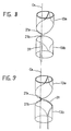
- Figs. 8 through 10 show, by way of example, feeding schemes for the antenna of Fig. 7.
- the coaxial cable 31 is arranged along the center line Ox passing through the vertex of the radiator 13b
- the coaxial cable 31 is arranged along the semicircular arc of the radiator 13b.
- a twin-lead type feeder 33 is placed between the radiators 13a and 13b.
- the vertexes 21 and 21b of the two radiators 13a and 12b are used as feeding points thereto.
- Fig. 11 is a perspective view illustrating an second embodiment of the present invention, which constitutes a monopole antenna by using the plane conductor ground plate 50 instead of using the radiator 12b or 13b in the embodiments of Figs. 6, 7 and 8. That is, the antenna of this embodiment comprises a radiator 13 formed by bending a substantially semicircular conductor disc into a cylindrical shape so that the center line Ox passing through the vertex of the semicircular arc is parallel to the center axis of the cylindrical shape, and the plane conductor ground plate 50 placed adjacent the vertex 21 of the circular arc of the radiator 13 virtually at right angles to the center line Ox passing through the vertex 21.
- the vertex 21 of the radiator 13 is used as a feeding point and power is fed via the coaxial cable 31 passing through a through hole 51 made in the plane conductor ground plate 50; namely, the coaxial cable 31 has its center conductor connected to the vertex 21 of the radiator 13 and its outer conductor connected to the plane conductor ground plate 50.
- this embodiment requires only one radiating element, one-half the number of those used in the first embodiment (Figs. 6 to 10), and hence permits reduction of the antenna height by half although it implements the same broadband characteristic as is obtainable with the first embodiment.
- the antenna of this embodiment is excellent in the space factor with a small antenna height.
- Figs. 12A, 12B and 12C are front, plan and right-hand side views of the antenna used in the experiment, and Fig. 12D is a development of the radiator 13 used.
- the radiator 13 was obtained by winding a semicircular conductor disc of a 75 mm radius r, shown in Fig. 12D, one tum around a 50 mm diameter column having its generating line defined by the center line Ox passing through the semicircular arc.
- the plane conductor ground plate 50 used was a 300 mm by 300 mm sheet of copper 0.2 mm thick.
- the power was fed via the feeding cable 31 passed through the through hole 51 made in the plane conductor ground plate centrally thereof.
- the coaxial cable 31 had its center conductor connected to the vertex 21 of the radiator 13 (Fig. 12C) and its outer conductor connected to the plane conductor ground plate 50.
- Fig. 13 there is shown the VSWR characteristic measured in the experiment. Comparison of the measured VSWR characteristic with that of the prior art example shown in Fig. 3 indicates that the antenna of this embodiment has the same broadband characteristic as that of the prior art example and that the VSWR values are smaller than those of the prior art over the entire band. That is, the VSWR characteristic of this antenna is improved in comparison with that of the prior art. With such a combined use of the cylindrical radiator and the plane conductor ground plate, the antenna of this embodiment has an excellent space factor in that the antenna height is reduced by half and the antenna width occupied by the radiator is one-third that in the prior art, besides the VSWR characteristic is also enhanced as compared with that of the prior art example.
- the radiator 13 While in the embodiments of Figs. 6 through 11 the radiator 13 is shown to be regular cylindrical In shape, it may also be elliptic-cylindrical. Let two axes of the elliptic-cylindrical radiator 13 be represented by an axis L 2 crossing the center line Ox at right angles and an axis L 1 crossing that L 2 at right angles as shown In Fig. 11. The VSWR characteristic was measured under the three conditions listed below.
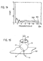
- Fig. 14 there are shown the VSWR characteristics measured under the above-mentioned conditions, which are indicated by the solid, dotted and broken lines 31A, 31B and 31C, respectively.
- the VSWR characteristic does not undergo any signlficant change even if the radiator 13 is elliptic-cylindrical in shape; hence, the radiator 13 need not always be cylindrical in shape but may also be elliptic-cylindrical in the range of the axis ratio L 1 /L 2 from about 0.5 to 1.5. This applies to all the embodiments described later on and to either of the radiators 13a and 13b.
- Fig. 16 shows the VSWR characteristics measured when the diameter D of the cylindrical radiator 13 was 48 mm (the gap d was 1 mm) and 60 mm (the gap d was 37 mm), the measured characteristics being indicated by the solid line 33A and the broken line 33B, respectively.
- the broadband characteristic of the antenna is retained also when the opposite ends of the cylindrical radiator 13 are held out of contact with each other. As the gap d Increases, the VSWR characteristic becomes degraded but if so, It is excellent more than In the prior art.
- Fig. 18 is a perspective view illustrating an antenna structure according to a third embodiment of the present invention.
- the antenna of this embodiment uses semicircular arcwise radiator 14 with a virtually semicircular notch 41 defined centrally thereof, which is obtained by forming a semicircular notch in a semicircular conductor disc to obtain a semicircular arcwise conductor (see Fig. 19D) and winding it one turn around a column whose generating line is defined by the center line Ox passing through the vertex of the semicircular arc of the semicircular arcwise conductor. That is, the radiator 14 is formed by the semicircular arcwise marginal portion of the radiator 13 depicted in Fig. 12D.
- the plane conductor ground plate 50 is disposed adjacent the vertex 21 of the circular arc of the radiator 14.
- the vertex 21 of the radiator 14 is used as the feeding point, to which power is fed from the coaxial cable 31 passed through the through hole 51 made in the plane conductor ground plate 50.
- the center conductor of the coaxial cable 31 is connected to the feeding point 21 of the radiator 14 and its outer conductor to the plane conductor ground plate 50.
- the antenna current in the semicircular radiating element is mostly distributed along the lower marginal edge of its semicircular arc and no antenna current flows along the upper straight side and in the central portion of the semicircular radiating element; that is, only the lower semicircular arcwise marginal portion contributes to the radiation of radio waves, and hence the notch 41 does not affect the antenna operation.
- the notch 41 need not always be semicircular (in the state of the radiator being developed) in shape but may also be semi-elliptic, for instance.
- FIGs. 19A, 19B and 19C are front, plan and right-hand side views of the antenna, and Fig. 19D a development of the radiator 14.
- Fig. 20A there is shown the VSWR characteristic measured in the experiment.
- a semicircular arcwise conductor plate of a 75 mm radius r 1 with the semicircular notch 41 of a 55 mm radius r 2 defined concentrically with the outside shape of the arcwise conductor plate was wound one turn around a 50 mm diameter column whose generating line was defined by the center line Ox passing through the vertex 21 of the semicircular arcwise conductor.
- the plane conductor ground plate 50 used was a 300 mm by 300 mm sheet of copper 0.2 mm thick.
- the power was fed via the feeding cable 31 passed through the through hole 51 made in the plane conductor ground plate 50 centrally thereof.
- the coaxial cable 31 had its center conductor connected to the vertex 21 of the radiator 14 and its outer conductor connected to the plane conductor ground plate 50.
- the broadband characteristic is the same as in the prior art even if the radiator has the notch 41.
- the VSWR is degraded in the band below 5 GHz, but when compared with the characteristic of the prior art shown in Fig. 3, the VSWR characteristic is not degraded in the low-frequency region and the VSWR is improved markedly rather in the high-frequency band.
- the notch 41 defined by the radiator 14 another antenna element can be placed in the notch 41; hence, the antenna of this embodiment is excellent in terms of space factor.
- Fig. 20B is a graph showing the relationship between the area ratio of the semicircular notch 41 to the semicircular arcwise radiator 14 and the worst VSWR in the operating band. From Fig. 20B it is seen that when the VSWR is allowed in the range to 2, the notch 41 can be increased up to about 50% in terms of the above-mentioned area ratio. This is approximately 0.7 in terms of the radius ratio r 2 /r 1 , indicating that the notch 41 can be made appreciably large.
- Fig. 21 is a perspective view illustrating an antenna structure according to a fourth embodiment of the present invention, which uses the same semicircular arcwise radiator 14 as that used in the third embodiment of Fig. 18 but differs therefrom in that a radiating element is placed in the notch 41 defined by the radiator 14.
- the plane conductor ground plate 50 is disposed adjacent the vertex 21 of the semicircular arc of the radiator 14.
- Placed in the notch 41 defined by the semicircular arcwise radiator 14 is a helical antenna 62, which is positioned above the vertex 21 with its axis held substantially vertical to the plane conductor ground plate 50.
- the coaxial cable 31 is passed through the through hole 51 of the plane conductor ground plate 50 and has its center conductor connected to the vertex 21 of the radiator 14 and its outer conductor connected to the plane conductor ground plate 50.
- the helical antenna 62 is supplied with power via the radiator 14.
- the helical antenna is incorporated as a second antenna in the antenna structure of Fig. 18.
- the band of the second antenna is arbitrary, but by selecting the second antenna whose operating band is lower than the lowest resonance frequency of the counterpart, multiresonance could be implemented. Further, by selecting the second antenna of a size that can be accommodated in the notch 41, the lowest resonance frequency could be reduced without increasing the size of the entire antenna structure.
- Figs. 22A, 22B and 22C are front, plan and right-hand side views of the antenna and Fig. 22D a development of the radiator 14.
- Figs. 23 and 24 there are shown the measured VSWR characteristic.
- Fig. 24 is a graph showing the VSWR characteristic over the frequency band O to 1 GHz with the abscissa on an enlarged scale.
- the radiator 14 was a semicircular arcwise conductor plate of a 75 mm radius r 1 with the semicircular notch 41 of a 55 mm radius r 2 defined concentrically with the outside shape of the arcwise conductor plate obtained by being wound one turn around a 50 mm diameter column whose generating line was defined by the center line Ox passing through the vertex 21 of the semicircular arcwise conductor.
- the helical antenna 62 as the second antenna adjusted to operate at 280 MHz was placed in the notch 41 and was connected at one end to the vertex 21 of the semicircular arc of the notch 41 of the radiator 14.
- the plane conductor ground plate 50 used was a 300 mm by 300 mm sheet of copper 0.2 mm thick.
- the power was fed via the feeding cable 31 passed through the through hole 51 made in the plane conductor ground plate 50 centrally thereof.
- the coaxial cable 31 had its center conductor connected to the vertex 21 of the radiator 14 and its outer conductor connected to the plane conductor ground plate 50.
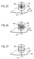
- Figs. 25, 26 and 27 illustrate modified forms of the fourth embodiment, which use two helical antennas 621 and 622, two meander monopoles 61 1 and 61 2 and one resistance-loaded monopole 63 to be placed in the notch 41 defined by the semicircular arcwise radiator 14, respectively.
- Any other types of radiating elements can be used as long as they can be accommodated in the notch 41. While in Figs. 25 and 26 two radiating elements are shown to be placed in the notch 41, the number of radiating elements is not limited specifically thereto.
- the radiating elements are supplied with power via the radiator 14 to which they are connected.
- the number of resonance frequencies of the antenna can be further increased.
- the resonance frequency of the resistance-loaded monopole 63 to be lower than the resonance frequency of the semicircular conductor monopole antenna formed by the radiator 14, the lowest resonance frequency can be lowered without upsizing the antenna structure, and hence the band can be made broader.
- the resonance frequencies and impedances of the radiating elements or element placed in the notch 41 and the radiator 14 are shifted to such an extent that their antenna operations do not affect each other.
- the semicircular radiator bent into a cylindrical shape occupies less space than in the prior art and the notch defined by the cylindrical semicircular arcwise radiator increases the space factor.
- an antenna element different in shape and operating band from the semicircular arcwise radiator it is possible to realize an antenna which is smaller in size but more broadband and more multiresonating or lower in the lowest resonance frequency that in the past.
Landscapes
- Waveguide Aerials (AREA)
- Details Of Aerials (AREA)
Description
- The present invention relates to an antenna which has a bandwidth as broad as 0.5 to 13 GHz, for instance, but is small in size and, more particularly, to an antenna using a semicircular radiator or semicircular, ribbon-shaped radiator.
- In R.M. Taylor, "A Broadband Omnidirectional Antenna," IEEE AP-S International Symposium, 1994, p1294, there is disclosed a conventional broadband antenna using semicircular conductor discs as depicted in Fig. 1, This conventional antenna has two elements. One of the elements is composed of two
semicircular conductor discs elements coaxial cable 31 for feeding is disposed along the center of one of the two elements, with the outer conductor of the cable held in contact with the element. - Fig. 2 illustrates a simplified version of the antenna depicted in Fig. 1, which has
semicircular conductor discs conductor discs coaxial cable 31 installed in theconductor disc 12b. - Fig. 3 shows the VSWR characteristic of the antenna depicted in Fig. 2. It will be seen from Fig. 3 that the simplified antenna also has a broadband characteristic, which was obtained when the radius r of each of the
semicircular conductor discs radiator 12a in the plane perpendicular to the center line Ox. - Thus, the conventional antenna of Fig. 1 comprises upper and lower pairs of antenna elements each formed by two sectorial radiators crossing each other, and hence it occupies much space. Also in the simplified antenna of Fig. 2, the sectorial semicircular radiators are space-consuming. In terms of size, too, the conventional antennas require semicircular conductor discs whose radii are at least around 1/8 of the lowest resonance wavelength; even the simplified antenna requires a 2r by 2r or (1/4)λ by (1/4)λ antenna area. Accordingly, the conventional antennas have defects that they are bulky and space-consuming and that when the lower limit frequency is lowered, they become bulky in inverse proportion to it.
- US-A-4,843,403 discloses a broadband notch antenna comprising a substrate having an outer surface, a first conducting radiator disposed on one side of the outer surface of said substrate and having a first curved edge, a second conducting radiator disposed on the other side of the outer surface of said substrate and having a second curved edge, said first and second curved edges being closely related to one another and spaced apart in close proximity at one point to define a feed-point gap therebetween with adjacent curved edges gradually tapering outwardly therefrom to define first and second continuous flared notches interfacing one another and emanating from said feed-point gap. The document mentiones that the substrate may be bent or folded transversely across the narrow slot portion to produce various degrees of a side by side dual flared notch antenna. Shown is a folded antenna structure that is more or less symmetrical in the manner of bending but the document indicates there are an infinite number of ways of folding, bending, rolling, etc., the structure.
- It is therefore an object of the present invention to provide an antenna which has the same electrical characteristics as in the prior art but is less bulky, or an antenna which is smaller in size and lower in the lowest resonance frequency than in the past.
- This object is achieved with an antenna as claimed in
claim 1. Preferred embodiments are subject-matter of the dependent claims. - The antenna is characterized in that a semicircular conductor disc as a radiator is bent into a cylindrical form.
- In the antenna according to the invention, it is also possible to employ a configuration in which a plane conductor ground plate is disposed opposite the vertex of the circular arc of the cylindrical radiator in a plane perpendicular thereto and the vertex of the circular arc is used as a feeding point, or a configuration in which another semicircular radiator having the vertex of its circular arc opposed to that of the cylindrical radiator is disposed in parallel thereto and the vertexes of their circular arcs are used as feeding points.
- In the antenna according to the invention, when the cylindrical semicircular radiator is a semicircular arcwise radiator with a virtually semicircular notch defined inside thereof, at least one radiating element different in shape therefrom may be disposed in the notch and connected to the vicinity of the feeding point.
- With the antenna according to the invention, it is possible to reduce the space for the antenna element while retaining the same broadband characteristic as in the past, by defining the semicircular notch in the semicircular radiator to form the arcwise radiator and/or bending the semicircular or arcwise radiator into a cylindrical form. Furthermore, by incorporating another radiating element in the notch of the semicircular radiator, it is possible to achieve a multiresonance antenna without upsizing the antenna element, and the VSWR characteristic can be improved as compared with that in the prior art by bending the semicircular radiator into a cylindrical form.
- Embodiments of the invention will be described below with reference to the drawings, in which:
- Fig. 1
- is a perspective view of a conventional antenna;
- Fig. 2
- is a perspective view showing a simplified version of the antenna of Fig. 1;
- Fig. 3
- is a graph showing the VSWR characteristic of the antenna depicted in Fig. 2;
- Fig. 4
- is a perspective view of a conventional antenna structure;
- Fig. 5A
- is diagram showing the current density distribution on a radiator of the antenna structure of Fig. 4;
- Fig. 5B
- is a graph showing the VSWR characteristics obtained with radiators of different shapes in the Fig. 4 structure;
- Fig. 6
- is a perspective view illustrating one mode of carrying out the sixth embodiment of the present invention;
- Fig. 7
- is a perspective view illustrating another mode of carrying out the sixth embodiment of the present invention;
- Fig. 8
- is a perspective view illustrating an example of the structure for feeding in the present invention;
- Fig. 9
- is a perspective view illustrating another example of the structure for feeding;
- Fig. 10
- is a perspective view illustrating still another example of the structure for feeding;
- Fig. 11
- is a perspective view of a first embodiment of the present invention;
- Fig. 12A
- is a front view of an antenna used for experiments of the first embodiment of the present invention;
- Fig. 12B
- is its plan view;
- Fig. 12C
- is its right-hand side view;
- Fig. 12D
- is a development of a
radiator 13; - Fig. 13
- is a graph showing the measured VSWR characteristic of the antenna of Figs. 12A to 12D;
- Fig. 14
- is a graph showing the VSWR characteristics measured for different axial lengths of the elliptic cylindrical radiator in Fig. 11;
- Fig. 15
- is a diagram for explaining the distance between opposite ends of a semicircular radiator bent into a cylindrical form;
- Fig. 16
- is a graph showing the VSWR characteristics measured for different distances between the opposite ends of the cylindrical radiator by changing the diameter of its cylindrical form;
- Fig. 17
- is a graph showing the VSWR characteristics measured in the cases where the opposite ends of the semicircular radiator are electrically connected and isolated, respectively;
- Fig. 18
- is a perspective view illustrating an second embodiment of the present invention;
- Fig. 19A
- is a front view of an antenna used for experiments of the second embodiment of the present invention;
- Fig. 19B
- is Its plan view;
- Fig. 19C
- is its right-hand side view;
- Fig. 19D
- is a development of a
radiator 14; - Fig. 20A
- is a graph showing the VSWR characteristic of the antenna of Figs. 19A to 19D;
- Fig. 20B
- is a graph showing, by way of example, the relationship between the area ratio of a notch to the radiator and the worst VSWR characteristic in the operating region;
- Fig. 21
- is a perspective view illustrating a third embodiment of the present invention;;
- Fig. 22A
- is a front view of an antenna used for experiments of a fourth embodiment of the present invention;
- Fig. 22B
- is its plan view;
- Fig. 22C
- is its right-hand side view;
- Fig. 23
- is a graph showing the measured VSWR characteristic of Figs. 22A to 22D;
- Fig. 24
- is a graph showing the low-frequency region on an enlarged scale in fig. 23;
- Fig. 25
- is a diagram Illustrating a modified form of the fourth embodiment;
- Fig. 26
- is a diagram illustrating another modification of the fourth embodiment; and
- Fig. 27
- is a diagram illustrating still another modification of the fourth embodiment.
- To facilitate a better understanding of the present invention, a description will be given first of a prior art monopole antenna which comprises a semicircular radiator disc, which is one of the radiating elements of the prior art dipole antenna shown In Fig. 1, and a plane conductor ground plate serving as a mirror image plane and is equivalent in operation to the antenna of Fig. 1. As shown in Fig. 4, the monopole antenna was formed by placing a
semiccircular radiator 12 on a planeconductor ground plate 50 vertically thereto with the vertex of the circular arc of the former held in adjacent but spaced relation to the latter and connecting center and outer conductors of a coaxial feeding cable to the vertex of the circular arc of thesemicircular radiator 12 and theground plate 50, respectively. And, as described just below, analyses were made of the monopole antenna shown in Fig. 4. Since theconductor ground plate 50 forms a mirror image of theradiator 12, the operation of this monopole antenna is equivalent to the operation of the antenna depicted in Fig. 2. - (a) The distribution of a 5 GHz high-frequency current on the
radiator 12 was analyzed by a finite element method, from which it was found that high current density regions developed discontinuously along the circumference of thesemicircular radiator 12 as shown by hatched areas in Fig. 5A, whereas the current flow in the central region was negligibly small-this indicates that the arcwise marginal area of the semicircular disc contributes largely to radiation. - (b) The shape of the
semicircular radiator 12 in Fig. 4 was defined generally as an ellipse inclusive of a circle and the influence of the dimensional relationship between perpendicularly intersecting first and second radii L1 and L2 of theradiator 12 on the VSWR characteristic was measured under the three conditions listed below. - (1) L1 = L2 = 75 mm (i.e. In the case of a semicircle)
- (2) L1 = 75 mm, L2 = 50 mm (i.e. When L1 > L2)
- (3) L1 = 40 mm, L2 = 75 mm (i.e. When L1 < L2)
-
- In Fig. 5B there are shown the VSWR characteristics measured under the above-said three conditions, which are indicated by the solid, broken and
thick lines radiator 12 need not always be perfectly semicircular in shape. - Based on the results of the analysis (a), a semicircular area of the semicircular radiator disc inside the arcwise marginal area thereof is cut out to define a semicircular notch, which is used to accommodate another antenna element or an electronic part or circuitry.
- According to the results of the analysis (b), the VSWR characteristic remains substantially unchanged regardless of whether the radiator is semicircular or semi-elliptic. This applies to an arcwise ribbon-shaped radiating conductor for use in the embodiments of the present invention described hereinbelow.
- A description will be given of embodiments in which at least one virtually semicircular radiator is wound one turn into a cylindrical shape to reduce the transverse length of the antenna.
- Fig. 6 is a perspective view illustrating the antenna structure of a first embodiment of the present invention, which is provided with a
radiator 13a formed by winding a virtually semicircular conductor disc one turn into a cylindrical shape so that its straight side forms substantially a circle, and aradiator 12b formed by a semicircular conductor disc. Theradiators vertexes vertexes feeding section 30 is provided between them. - Fig. 7 illustrates in perspective a modified form of the Fig. 7 embodiment, which is provided with
radiators radiators vertexes - As described above, one of the two radiators forming the antenna may be such a
cylindrical radiator 13a as shown in Fig. 6, or the both radiators may be suchcylindrical radiators curved radiator 13a (Fig. 6) orradiators - In the embodiments of Figs. 6 and 7, the opposite ends of the
cylindrical radiator 13a (also 13b in Fig. 7) in the circumferential direction thereof are separated by asmall gap 10. It is preferable that a straight-line d joining the center line Ox of thecylindrical radiator 13a and the center of thegap 10 be approximately at right angles to the former. In Fig. 7 it is desirable that straight lines d joining the center line Ox common to theradiators respective gaps 10 be substantially parallel to each other. Theradiators radiator - With the use of such a cylindrical radiator, the transverse width that is occupied by at least one radiating element is reduced down to about 1/3 that needed in the prior art example using a flat radiator, and hence the space factor can be increased accordingly.
- Figs. 8 through 10 show, by way of example, feeding schemes for the antenna of Fig. 7. In Fig. 8 the
coaxial cable 31 is arranged along the center line Ox passing through the vertex of theradiator 13b, whereas in Fig. 9 thecoaxial cable 31 is arranged along the semicircular arc of theradiator 13b. In Fig. 10 a twin-lead type feeder 33 is placed between theradiators - In any case, the
vertexes radiators - Fig. 11 is a perspective view illustrating an second embodiment of the present invention, which constitutes a monopole antenna by using the plane
conductor ground plate 50 instead of using theradiator radiator 13 formed by bending a substantially semicircular conductor disc into a cylindrical shape so that the center line Ox passing through the vertex of the semicircular arc is parallel to the center axis of the cylindrical shape, and the planeconductor ground plate 50 placed adjacent thevertex 21 of the circular arc of theradiator 13 virtually at right angles to the center line Ox passing through thevertex 21. Thevertex 21 of theradiator 13 is used as a feeding point and power is fed via thecoaxial cable 31 passing through a throughhole 51 made in the planeconductor ground plate 50; namely, thecoaxial cable 31 has its center conductor connected to thevertex 21 of theradiator 13 and its outer conductor connected to the planeconductor ground plate 50. - In this embodiment an electrical mirror image of the radiating
element 13 is formed by the planeconductor ground plate 50 on the reverse side thereof. Accordingly, this embodiment requires only one radiating element, one-half the number of those used in the first embodiment (Figs. 6 to 10), and hence permits reduction of the antenna height by half although it implements the same broadband characteristic as is obtainable with the first embodiment. Thus, the antenna of this embodiment is excellent in the space factor with a small antenna height. - An experiments was carried out to confirm the performance of the antenna of this embodiment. Figs. 12A, 12B and 12C are front, plan and right-hand side views of the antenna used in the experiment, and Fig. 12D is a development of the
radiator 13 used. Theradiator 13 was obtained by winding a semicircular conductor disc of a 75 mm radius r, shown in Fig. 12D, one tum around a 50 mm diameter column having its generating line defined by the center line Ox passing through the semicircular arc. The planeconductor ground plate 50 used was a 300 mm by 300 mm sheet of copper 0.2 mm thick. The power was fed via the feedingcable 31 passed through the throughhole 51 made in the plane conductor ground plate centrally thereof. Thecoaxial cable 31 had its center conductor connected to thevertex 21 of the radiator 13 (Fig. 12C) and its outer conductor connected to the planeconductor ground plate 50. - In Fig. 13 there is shown the VSWR characteristic measured in the experiment. Comparison of the measured VSWR characteristic with that of the prior art example shown in Fig. 3 indicates that the antenna of this embodiment has the same broadband characteristic as that of the prior art example and that the VSWR values are smaller than those of the prior art over the entire band. That is, the VSWR characteristic of this antenna is improved in comparison with that of the prior art. With such a combined use of the cylindrical radiator and the plane conductor ground plate, the antenna of this embodiment has an excellent space factor in that the antenna height is reduced by half and the antenna width occupied by the radiator is one-third that in the prior art, besides the VSWR characteristic is also enhanced as compared with that of the prior art example.
- While in the embodiments of Figs. 6 through 11 the
radiator 13 is shown to be regular cylindrical In shape, it may also be elliptic-cylindrical. Let two axes of the elliptic-cylindrical radiator 13 be represented by an axis L2 crossing the center line Ox at right angles and an axis L1 crossing that L2 at right angles as shown In Fig. 11. The VSWR characteristic was measured under the three conditions listed below. - (1) L1=L2=50 (cylindrical)
- (2) L1=33 mm, L2=60 mm (an elliptic cylinder with L1>L2)
- (3) L1=60 mm, L2=33 mm (an elliptic cylinder with L1<L2)
-
- In Fig. 14 there are shown the VSWR characteristics measured under the above-mentioned conditions, which are indicated by the solid, dotted and broken lines 31A, 31B and 31C, respectively. As is evident from Fig. 14, the VSWR characteristic does not undergo any signlficant change even if the
radiator 13 is elliptic-cylindrical in shape; hence, theradiator 13 need not always be cylindrical in shape but may also be elliptic-cylindrical in the range of the axis ratio L1/L2 from about 0.5 to 1.5. This applies to all the embodiments described later on and to either of theradiators - Although in the embodiments of Figs. 6 through 11 the
cylindrical radiator 13 is shown to have its opposite ends held substantially in contact with each other, the opposite ends may also be separated by a gap d as shown in Fig. 15. Fig. 16 shows the VSWR characteristics measured when the diameter D of thecylindrical radiator 13 was 48 mm (the gap d was 1 mm) and 60 mm (the gap d was 37 mm), the measured characteristics being indicated by thesolid line 33A and thebroken line 33B, respectively. The broadband characteristic of the antenna is retained also when the opposite ends of thecylindrical radiator 13 are held out of contact with each other. As the gap d Increases, the VSWR characteristic becomes degraded but if so, It is excellent more than In the prior art. - In Fig. 17 there are indicated by the
broken line 34A and thesolid line 34B, respectively, VSWR characteristics measured in the cases where the opposite ends of theradiator 13 were soldered to each other (d=0) and where the opposite ends were slightly held (around 1 mm) apart. As is evident from Fig. 17, the VSWR characteristic remains substantially unchanged irrespective of whether the opposite ends of thecylindrical radiator 13 are in contact with each other or not. Hence, the opposite ends need not always be held in contact. This applies to all the other embodiments of the present invention. - Fig. 18 is a perspective view illustrating an antenna structure according to a third embodiment of the present invention. The antenna of this embodiment uses
semicircular arcwise radiator 14 with a virtuallysemicircular notch 41 defined centrally thereof, which is obtained by forming a semicircular notch in a semicircular conductor disc to obtain a semicircular arcwise conductor (see Fig. 19D) and winding it one turn around a column whose generating line is defined by the center line Ox passing through the vertex of the semicircular arc of the semicircular arcwise conductor. That is, theradiator 14 is formed by the semicircular arcwise marginal portion of theradiator 13 depicted in Fig. 12D. As is the case with Fig. 11, the planeconductor ground plate 50 is disposed adjacent thevertex 21 of the circular arc of theradiator 14. - The
vertex 21 of theradiator 14 is used as the feeding point, to which power is fed from thecoaxial cable 31 passed through the throughhole 51 made in the planeconductor ground plate 50. The center conductor of thecoaxial cable 31 is connected to thefeeding point 21 of theradiator 14 and its outer conductor to the planeconductor ground plate 50. With the provision of thenotch 41 defined by thesemicircular arcwise radiator 14, the space efficiency can be increased higher than in the case of the first or second embodiment which uses the radiator formed by merely winding a semicircular conductor disc into a cylindrical shape with no notch. As referred to previously with respect to Fig. 5A, the antenna current in the semicircular radiating element is mostly distributed along the lower marginal edge of its semicircular arc and no antenna current flows along the upper straight side and in the central portion of the semicircular radiating element; that is, only the lower semicircular arcwise marginal portion contributes to the radiation of radio waves, and hence thenotch 41 does not affect the antenna operation. Thenotch 41 need not always be semicircular (in the state of the radiator being developed) in shape but may also be semi-elliptic, for instance. - An experiment was conducted to confirm the performance of this antenna. Figs. 19A, 19B and 19C are front, plan and right-hand side views of the antenna, and Fig. 19D a development of the
radiator 14. In Fig. 20A there is shown the VSWR characteristic measured in the experiment. To obtain theradiator 14, a semicircular arcwise conductor plate of a 75 mm radius r1 with thesemicircular notch 41 of a 55 mm radius r2 defined concentrically with the outside shape of the arcwise conductor plate was wound one turn around a 50 mm diameter column whose generating line was defined by the center line Ox passing through thevertex 21 of the semicircular arcwise conductor. The planeconductor ground plate 50 used was a 300 mm by 300 mm sheet of copper 0.2 mm thick. The power was fed via the feedingcable 31 passed through the throughhole 51 made in the planeconductor ground plate 50 centrally thereof. Thecoaxial cable 31 had its center conductor connected to thevertex 21 of theradiator 14 and its outer conductor connected to the planeconductor ground plate 50. - When the VSWR characteristic obtained in the experiment (Fig. 20A) is compared with the VSWR characteristic (Fig. 13) of the antenna of Fig. 12 without the
notch 41, it is seen that the broadband characteristic is the same as in the prior art even if the radiator has thenotch 41. In this instance, the VSWR is degraded in the band below 5 GHz, but when compared with the characteristic of the prior art shown in Fig. 3, the VSWR characteristic is not degraded in the low-frequency region and the VSWR is improved markedly rather in the high-frequency band. With the provision of thenotch 41 defined by theradiator 14, another antenna element can be placed in thenotch 41; hence, the antenna of this embodiment is excellent in terms of space factor. - Fig. 20B is a graph showing the relationship between the area ratio of the
semicircular notch 41 to thesemicircular arcwise radiator 14 and the worst VSWR in the operating band. From Fig. 20B it is seen that when the VSWR is allowed in the range to 2, thenotch 41 can be increased up to about 50% in terms of the above-mentioned area ratio. This is approximately 0.7 in terms of the radius ratio r2/r1, indicating that thenotch 41 can be made appreciably large. - Fig. 21 is a perspective view illustrating an antenna structure according to a fourth embodiment of the present invention, which uses the same
semicircular arcwise radiator 14 as that used in the third embodiment of Fig. 18 but differs therefrom in that a radiating element is placed in thenotch 41 defined by theradiator 14. The planeconductor ground plate 50 is disposed adjacent thevertex 21 of the semicircular arc of theradiator 14. Placed in thenotch 41 defined by thesemicircular arcwise radiator 14 is ahelical antenna 62, which is positioned above thevertex 21 with its axis held substantially vertical to the planeconductor ground plate 50. Thecoaxial cable 31 is passed through the throughhole 51 of the planeconductor ground plate 50 and has its center conductor connected to thevertex 21 of theradiator 14 and its outer conductor connected to the planeconductor ground plate 50. Thehelical antenna 62 is supplied with power via theradiator 14. - In this embodiment, the helical antenna is incorporated as a second antenna in the antenna structure of Fig. 18. The band of the second antenna is arbitrary, but by selecting the second antenna whose operating band is lower than the lowest resonance frequency of the counterpart, multiresonance could be implemented. Further, by selecting the second antenna of a size that can be accommodated in the
notch 41, the lowest resonance frequency could be reduced without increasing the size of the entire antenna structure. - An experiment was made to confirm the performance of the antenna of this embodiment. Figs. 22A, 22B and 22C are front, plan and right-hand side views of the antenna and Fig. 22D a development of the
radiator 14. In Figs. 23 and 24 there are shown the measured VSWR characteristic. Fig. 24 is a graph showing the VSWR characteristic over the frequency band O to 1 GHz with the abscissa on an enlarged scale. Theradiator 14 was a semicircular arcwise conductor plate of a 75 mm radius r1 with thesemicircular notch 41 of a 55 mm radius r2 defined concentrically with the outside shape of the arcwise conductor plate obtained by being wound one turn around a 50 mm diameter column whose generating line was defined by the center line Ox passing through thevertex 21 of the semicircular arcwise conductor. Thehelical antenna 62 as the second antenna adjusted to operate at 280 MHz was placed in thenotch 41 and was connected at one end to thevertex 21 of the semicircular arc of thenotch 41 of theradiator 14. The planeconductor ground plate 50 used was a 300 mm by 300 mm sheet of copper 0.2 mm thick. The power was fed via the feedingcable 31 passed through the throughhole 51 made in the planeconductor ground plate 50 centrally thereof. Thecoaxial cable 31 had its center conductor connected to thevertex 21 of theradiator 14 and its outer conductor connected to the planeconductor ground plate 50. When the experimental results shown in Fig. 23 are compared with those of the third embodiment in Fig. 20A,
it is seen that the same band characteristic is obtained even if thehelical antenna 62 is incorporated in thenotch 41. Fig. 24 indicates that the combined use of theradiator 14 and thehelical antenna 62 permits resonance at 280 Mhz as well. Thus, it is possible to achieve multiresonance and lower the lowest resonance frequency without changing the size of the antenna structure. - Figs. 25, 26 and 27 illustrate modified forms of the fourth embodiment, which use two
helical antennas monopole 63 to be placed in thenotch 41 defined by thesemicircular arcwise radiator 14, respectively. Any other types of radiating elements can be used as long as they can be accommodated in thenotch 41. While in Figs. 25 and 26 two radiating elements are shown to be placed in thenotch 41, the number of radiating elements is not limited specifically thereto. The radiating elements are supplied with power via theradiator 14 to which they are connected. - By selecting a different resonance frequency for each of the radiating elements placed in the
notch 41 defined by thesemicircular arcwise radiator 14, the number of resonance frequencies of the antenna can be further increased. In the case of Fig. 27, by setting the resonance frequency of the resistance-loadedmonopole 63 to be lower than the resonance frequency of the semicircular conductor monopole antenna formed by theradiator 14, the lowest resonance frequency can be lowered without upsizing the antenna structure, and hence the band can be made broader. The resonance frequencies and impedances of the radiating elements or element placed in thenotch 41 and theradiator 14 are shifted to such an extent that their antenna operations do not affect each other. - As described above, according to the present invention, the semicircular radiator bent into a cylindrical shape occupies less space than in the prior art and the notch defined by the cylindrical semicircular arcwise radiator increases the space factor. By placing in the notch an antenna element different in shape and operating band from the semicircular arcwise radiator, it is possible to realize an antenna which is smaller in size but more broadband and more multiresonating or lower in the lowest resonance frequency that in the past.
Claims (8)
- An antenna comprising at least one radiator (13a) and characterized in that said radiator (13a) is composed of a virtually semicircular conductor disc wound one turn into a cylindrical shape so that its straight side forms substantially a circle and the opposite ends of the cylindrical radiator in the circumferential direction are adjacent to each other with a gap (d) defined in between, the gap being equal to or smaller than half the radius of said semicircular disk.
- The antenna of claim 1, further comprising:a plane conductor ground plate (50) disposed opposite the vertex of the semicircular arc of said radiator (13) at substantially right angles to the generating line of said cylindrical shape; anda feeder (31) connected to the vertex of said semicircular arc of said radiator (13) and said plane conductor ground plate (50), for feeding power to them.
- The antenna of claim 1, further comprising:another radiator (12b) having its center line aligned with that of said semicircular conductor disc and having an arcwise marginal edge opposed to the semicircular arc of said radiator (13a); anda feeder (30) connected to the vertex of the circular arc of said radiator and the vertex of the circular arc of said another radiator, for feeding power to them.
- The antenna of claim 3, wherein said other radiator is formed by another semicircular conductor disc.
- The antenna of claim 3, wherein said other radiator is a cylindrical radiator (13b) formed by winding another semicircular conductor disc into a virtually cylindrical shape.
- The antenna of claim 2 or 3, wherein said radiator comprises a semicircular ring obtained from said semicircular conductor disc provided with a virtually semicircular notch (41) substantially concentrical with the semicircular shape of said conductor disc, said semicircular ring being wound one turn.
- The antenna of claim 6, wherein at least one radiating element (62) different in shape from said semicircular radiating element is placed in said notch (41) and connected to said radiating element bent into the cylindrical shape.
- The antenna of claim 7, wherein said at least one radiating element (611, 612;62; 621, 622) is any one of a meander monopole, a resistance-loaded monopole and a helical antenna.
Priority Applications (1)
| Application Number | Priority Date | Filing Date | Title |
|---|---|---|---|
| EP02013954A EP1249893B1 (en) | 1995-09-27 | 1996-09-19 | Broadband antenna using semicircular radiator |
Applications Claiming Priority (6)
| Application Number | Priority Date | Filing Date | Title |
|---|---|---|---|
| JP24971295 | 1995-09-27 | ||
| JP249712/95 | 1995-09-27 | ||
| JP24971295 | 1995-09-27 | ||
| JP321906/95 | 1995-12-11 | ||
| JP32190695 | 1995-12-11 | ||
| JP32190695 | 1995-12-11 |
Related Child Applications (1)
| Application Number | Title | Priority Date | Filing Date |
|---|---|---|---|
| EP02013954A Division EP1249893B1 (en) | 1995-09-27 | 1996-09-19 | Broadband antenna using semicircular radiator |
Publications (3)
| Publication Number | Publication Date |
|---|---|
| EP0766343A2 EP0766343A2 (en) | 1997-04-02 |
| EP0766343A3 EP0766343A3 (en) | 1998-02-04 |
| EP0766343B1 true EP0766343B1 (en) | 2003-04-09 |
Family
ID=26539435
Family Applications (2)
| Application Number | Title | Priority Date | Filing Date |
|---|---|---|---|
| EP02013954A Expired - Lifetime EP1249893B1 (en) | 1995-09-27 | 1996-09-19 | Broadband antenna using semicircular radiator |
| EP96115061A Expired - Lifetime EP0766343B1 (en) | 1995-09-27 | 1996-09-19 | Broadband antenna using a semicircular radiator |
Family Applications Before (1)
| Application Number | Title | Priority Date | Filing Date |
|---|---|---|---|
| EP02013954A Expired - Lifetime EP1249893B1 (en) | 1995-09-27 | 1996-09-19 | Broadband antenna using semicircular radiator |
Country Status (6)
| Country | Link |
|---|---|
| US (1) | US5872546A (en) |
| EP (2) | EP1249893B1 (en) |
| KR (1) | KR100211229B1 (en) |
| CN (1) | CN1091307C (en) |
| CA (1) | CA2186186C (en) |
| DE (2) | DE69627262T2 (en) |
Cited By (2)
| Publication number | Priority date | Publication date | Assignee | Title |
|---|---|---|---|---|
| US8253633B2 (en) | 2002-12-22 | 2012-08-28 | Fractus, S.A. | Multi-band monopole antenna for a mobile communications device |
| US8456365B2 (en) | 2002-12-22 | 2013-06-04 | Fractus, S.A. | Multi-band monopole antennas for mobile communications devices |
Families Citing this family (107)
| Publication number | Priority date | Publication date | Assignee | Title |
|---|---|---|---|---|
| DE19935792A1 (en) * | 1999-07-29 | 2001-02-01 | Intershop Software Entwicklung | Networked computer system for information exchange by address data field or uniform resource locator (URL), has server computer provided with an URL having address information for clear identification of server computer |
| DE29925006U1 (en) | 1999-09-20 | 2008-04-03 | Fractus, S.A. | Multilevel antenna |
| ES2205898T3 (en) | 1999-10-26 | 2004-05-01 | Fractus, S.A. | MULTIBAND CLUSTERS OF INTERRELATED ANTENNAS. |
| CN100373693C (en) * | 2000-01-19 | 2008-03-05 | 弗拉克托斯股份有限公司 | Space-filling small antenna |
| JP2003520542A (en) * | 2000-01-19 | 2003-07-02 | フラクトゥス・ソシエダッド・アノニマ | Fractal and space-filled transmission lines, resonators, filters and elements for passive networks |
| US6329951B1 (en) * | 2000-04-05 | 2001-12-11 | Research In Motion Limited | Electrically connected multi-feed antenna system |
| NZ504042A (en) * | 2000-04-14 | 2002-12-20 | Gregory Daniel Hall | A wide-band high-gain plate dipole antenna using a pair of plate elements arranged in the same plane |
| EP1313166B1 (en) * | 2000-04-19 | 2007-11-14 | Advanced Automotive Antennas, S.L. | Multilevel advanced antenna for motor vehicles |
| US6845253B1 (en) * | 2000-09-27 | 2005-01-18 | Time Domain Corporation | Electromagnetic antenna apparatus |
| US7511675B2 (en) * | 2000-10-26 | 2009-03-31 | Advanced Automotive Antennas, S.L. | Antenna system for a motor vehicle |
| EP1358696A1 (en) | 2001-02-07 | 2003-11-05 | Fractus, S.A. | Miniature broadband ring-like microstrip patch antenna |
| US6664930B2 (en) | 2001-04-12 | 2003-12-16 | Research In Motion Limited | Multiple-element antenna |
| CN1507673A (en) * | 2001-04-16 | 2004-06-23 | �����ɷ� | Dual-band dual-polarized antenna array |
| US6512488B2 (en) * | 2001-05-15 | 2003-01-28 | Time Domain Corporation | Apparatus for establishing signal coupling between a signal line and an antenna structure |
| US6642903B2 (en) * | 2001-05-15 | 2003-11-04 | Time Domain Corporation | Apparatus for establishing signal coupling between a signal line and an antenna structure |
| WO2003034545A1 (en) * | 2001-10-16 | 2003-04-24 | Fractus, S.A. | Multifrequency microstrip patch antenna with parasitic coupled elements |
| US9755314B2 (en) | 2001-10-16 | 2017-09-05 | Fractus S.A. | Loaded antenna |
| WO2003034544A1 (en) | 2001-10-16 | 2003-04-24 | Fractus, S.A. | Multiband antenna |
| EP1444751B1 (en) * | 2001-10-16 | 2007-06-13 | Fractus, S.A. | Loaded antenna |
| ES2190749B1 (en) | 2001-11-30 | 2004-06-16 | Fractus, S.A | "CHAFF" MULTINIVEL AND / OR "SPACE-FILLING" DISPERSORS, AGAINST RADAR. |
| JP2003329067A (en) * | 2002-05-16 | 2003-11-19 | Advics:Kk | Disc brake |
| DE60329793D1 (en) * | 2002-06-21 | 2009-12-03 | Research In Motion Ltd | Multiple element antenna with parasitic coupler |
| WO2004010532A1 (en) * | 2002-07-15 | 2004-01-29 | Fractus, S.A. | Antenna with one or more holes |
| CN1295814C (en) * | 2002-10-25 | 2007-01-17 | 智邦科技股份有限公司 | Flat-panel antenna and wireless network device using the antenna |
| JP4170828B2 (en) * | 2002-11-27 | 2008-10-22 | 太陽誘電株式会社 | Antenna and dielectric substrate for antenna |
| JP2004328703A (en) * | 2002-11-27 | 2004-11-18 | Taiyo Yuden Co Ltd | Antenna |
| JP2004328693A (en) * | 2002-11-27 | 2004-11-18 | Taiyo Yuden Co Ltd | Antenna and dielectric substrate for antenna |
| AU2003252503A1 (en) * | 2002-11-27 | 2004-06-18 | Taiyoyuden Co., Ltd. | Antenna, dielectric substrate for antenna, radio communication card |
| JP2004328694A (en) * | 2002-11-27 | 2004-11-18 | Taiyo Yuden Co Ltd | Antenna and wireless communication card |
| US6791500B2 (en) | 2002-12-12 | 2004-09-14 | Research In Motion Limited | Antenna with near-field radiation control |
| CA2414718C (en) | 2002-12-17 | 2005-11-22 | Research In Motion Limited | Dual mode antenna system for radio transceiver |
| JP3833609B2 (en) * | 2002-12-27 | 2006-10-18 | 本田技研工業株式会社 | Car antenna |
| AU2003280780A1 (en) * | 2003-01-24 | 2004-08-13 | Yokohama Tlo Company, Ltd. | Wideband antenna |
| AU2003280779A1 (en) * | 2003-01-24 | 2004-08-13 | Yokohama Tlo Company, Ltd. | Wideband antenna |
| FR2850794A1 (en) * | 2003-01-30 | 2004-08-06 | Thomson Licensing Sa | BROADBAND ANTENNA WITH OMNIDIRECTIONAL RADIATION |
| EP1593180A1 (en) * | 2003-02-14 | 2005-11-09 | Huber + Suhner Ag | Wideband monopole antenna |
| JP2004318466A (en) * | 2003-04-16 | 2004-11-11 | Matsushita Electric Ind Co Ltd | Gift certificate, gift certificate issuing system and gift certificate use system |
| US7973733B2 (en) * | 2003-04-25 | 2011-07-05 | Qualcomm Incorporated | Electromagnetically coupled end-fed elliptical dipole for ultra-wide band systems |
| EP1478047B1 (en) | 2003-05-14 | 2007-10-03 | Research In Motion Limited | Antenna with multiple-band patch and slot structures |
| EP1912279B1 (en) * | 2003-06-12 | 2011-01-05 | Research In Motion Limited | Multiple-element antenna with electromagnetically coupled floating antenna element |
| US6980173B2 (en) * | 2003-07-24 | 2005-12-27 | Research In Motion Limited | Floating conductor pad for antenna performance stabilization and noise reduction |
| KR100846487B1 (en) * | 2003-12-08 | 2008-07-17 | 삼성전자주식회사 | Ultra-wideband antenna with isotropic radiation pattern |
| EP1542314A1 (en) * | 2003-12-11 | 2005-06-15 | Sony International (Europe) GmbH | Three-dimensional omni-directional monopole antenna designs for ultra- wideband applications |
| US7446726B2 (en) * | 2003-12-25 | 2008-11-04 | Samsung Electronics Co., Ltd. | Antenna |
| JP4002553B2 (en) * | 2003-12-26 | 2007-11-07 | アンテン株式会社 | antenna |
| WO2005070022A2 (en) * | 2004-01-22 | 2005-08-04 | Hans Gregory Schantz | Broadband electric-magnetic antenna apparatus and system |
| US7432858B2 (en) | 2004-03-17 | 2008-10-07 | Andrew Corporation | Printed circuit board wireless access point antenna |
| JP3863533B2 (en) * | 2004-03-22 | 2006-12-27 | 株式会社ヨコオ | Folded antenna |
| RU2281589C2 (en) * | 2004-03-31 | 2006-08-10 | Федеральное Государственное Унитарное Предприятие "Нижегородский Научно-Исследовательский Институт Радиотехники" | Extended-range superhigh-frequency dipole antenna |
| US7202819B2 (en) * | 2004-04-14 | 2007-04-10 | Qualcomm Incorporated | Tapered multiband antenna |
| US7369089B2 (en) * | 2004-05-13 | 2008-05-06 | Research In Motion Limited | Antenna with multiple-band patch and slot structures |
| JP4018698B2 (en) * | 2004-07-12 | 2007-12-05 | 株式会社東芝 | Broadband antenna and communication apparatus including the broadband antenna |
| JP2006086973A (en) * | 2004-09-17 | 2006-03-30 | Fujitsu Component Ltd | Antenna device |
| US7183977B2 (en) * | 2004-09-28 | 2007-02-27 | Intel Corporation | Antennas for multicarrier communications and multicarrier transceiver |
| US7782269B2 (en) | 2004-11-12 | 2010-08-24 | Fractus, S.A. | Antenna structure for a wireless device with a ground plane shaped as a loop |
| US7158089B2 (en) * | 2004-11-29 | 2007-01-02 | Qualcomm Incorporated | Compact antennas for ultra wide band applications |
| KR100683177B1 (en) * | 2005-01-18 | 2007-02-15 | 삼성전자주식회사 | Ultra Wide Band Substrate Dipole Antenna with Stable Radiation Pattern |
| DE102005003685B4 (en) * | 2005-01-26 | 2021-02-11 | Rohde & Schwarz GmbH & Co. Kommanditgesellschaft | Antenna with reflector |
| US7183978B1 (en) * | 2005-03-07 | 2007-02-27 | Bae Systems Information And Electronic Systems Integration Inc. | Wideband omnidirectional antenna |
| DE102005034966B4 (en) * | 2005-07-22 | 2013-10-17 | Universität Kassel | Ultra broadband antenna |
| JP2007123982A (en) * | 2005-10-25 | 2007-05-17 | Sony Ericsson Mobilecommunications Japan Inc | Multiband compatible antenna system and communication terminal |
| US7327318B2 (en) * | 2006-02-28 | 2008-02-05 | Mti Wireless Edge, Ltd. | Ultra wide band flat antenna |
| US7679575B1 (en) * | 2006-06-15 | 2010-03-16 | The United States Of America As Represented By The Secretary Of The Navy | Tapered slot antenna cylindrical array |
| US8738103B2 (en) | 2006-07-18 | 2014-05-27 | Fractus, S.A. | Multiple-body-configuration multimedia and smartphone multifunction wireless devices |
| FR2911725B1 (en) | 2007-01-24 | 2011-02-18 | Groupe Ecoles Telecomm | ANTENNA OR ANTENNA MEMBER ULTRA-LARGE BAND. |
| US7671817B2 (en) | 2007-02-27 | 2010-03-02 | Sony Ericsson Mobile Communications Ab | Wideband antenna |
| JP4844748B2 (en) * | 2007-03-15 | 2011-12-28 | ミツミ電機株式会社 | Broadband antenna device |
| US8228257B2 (en) * | 2008-03-21 | 2012-07-24 | First Rf Corporation | Broadband antenna system allowing multiple stacked collinear devices |
| WO2010008269A1 (en) * | 2008-07-14 | 2010-01-21 | Laird Technologies, Inc. | Multi-band antenna assemblies for use with wireless application devices |
| AU325814S (en) * | 2008-12-26 | 2009-04-23 | Nec Corp | Antenna |
| JP5456762B2 (en) * | 2009-03-31 | 2014-04-02 | 株式会社フジクラ | Broadband antenna |
| US8514136B2 (en) | 2009-10-26 | 2013-08-20 | The Boeing Company | Conformal high frequency antenna |
| DE102010004503B4 (en) * | 2010-01-13 | 2015-08-20 | Continental Automotive Gmbh | Antenna structure for a vehicle for multiple frequency bands |
| US9525488B2 (en) | 2010-05-02 | 2016-12-20 | Corning Optical Communications LLC | Digital data services and/or power distribution in optical fiber-based distributed communications systems providing digital data and radio frequency (RF) communications services, and related components and methods |
| DE102010026698A1 (en) * | 2010-07-07 | 2012-01-12 | Funkwerk Dabendorf Gmbh | Arrangement for the wireless connection of a radio |
| EP2606707A1 (en) | 2010-08-16 | 2013-06-26 | Corning Cable Systems LLC | Remote antenna clusters and related systems, components, and methods supporting digital data signal propagation between remote antenna units |
| US9252874B2 (en) | 2010-10-13 | 2016-02-02 | Ccs Technology, Inc | Power management for remote antenna units in distributed antenna systems |
| TWI474560B (en) * | 2011-01-10 | 2015-02-21 | Accton Technology Corp | Asymmetric dipole antenna |
| CN203504582U (en) | 2011-02-21 | 2014-03-26 | 康宁光缆系统有限责任公司 | Distributed antenna system and power supply device for distributing power therein |
| CN103036008B (en) * | 2011-10-08 | 2015-02-18 | 智邦科技股份有限公司 | Asymmetric dipole antenna |
| CN102593580B (en) * | 2012-03-29 | 2014-04-02 | 哈尔滨工业大学 | Ultra-wideband omnidirectional radiation bipolar wire antenna |
| CN102694253B (en) * | 2012-06-11 | 2014-02-12 | 哈尔滨工业大学 | Balance microstrip line feed ultra-wideband dipole antenna |
| US9716309B1 (en) * | 2012-06-12 | 2017-07-25 | Rockwell Collins, Inc. | Multifunctional, multi-beam circular BAVA array |
| US9590310B1 (en) * | 2013-03-12 | 2017-03-07 | Greenwave Scientific, Inc. | Shaped antenna of planar conducting material |
| DE102013005001A1 (en) * | 2013-03-24 | 2014-09-25 | Heinz Lindenmeier | Broadband monopole antenna for two frequency bands separated by a frequency gap in the decimeter wave range for vehicles |
| CN103346388A (en) * | 2013-07-09 | 2013-10-09 | 哈尔滨工业大学 | Ultra wide band monopole antenna |
| US10659163B2 (en) | 2014-09-25 | 2020-05-19 | Corning Optical Communications LLC | Supporting analog remote antenna units (RAUs) in digital distributed antenna systems (DASs) using analog RAU digital adaptors |
| WO2016071902A1 (en) * | 2014-11-03 | 2016-05-12 | Corning Optical Communications Wireless Ltd. | Multi-band monopole planar antennas configured to facilitate improved radio frequency (rf) isolation in multiple-input multiple-output (mimo) antenna arrangement |
| WO2016075696A1 (en) | 2014-11-13 | 2016-05-19 | Corning Optical Communications Wireless Ltd. | Analog distributed antenna systems (dass) supporting distribution of digital communications signals interfaced from a digital signal source and analog radio frequency (rf) communications signals |
| WO2016098111A1 (en) | 2014-12-18 | 2016-06-23 | Corning Optical Communications Wireless Ltd. | Digital- analog interface modules (da!ms) for flexibly.distributing digital and/or analog communications signals in wide-area analog distributed antenna systems (dass) |
| WO2016098109A1 (en) | 2014-12-18 | 2016-06-23 | Corning Optical Communications Wireless Ltd. | Digital interface modules (dims) for flexibly distributing digital and/or analog communications signals in wide-area analog distributed antenna systems (dass) |
| DE202015001972U1 (en) * | 2015-03-09 | 2016-03-10 | Sputnik24 Communication Systems GmbH | Multifunction antenna system with RADAR reflector |
| US10199745B2 (en) | 2015-06-04 | 2019-02-05 | The Boeing Company | Omnidirectional antenna system |
| EP3375043B1 (en) * | 2015-11-09 | 2021-08-18 | Wiser Systems, Inc. | Ultra-wideband (uwb) antennas and related enclosures for the uwb antennas |
| CN105811086B (en) * | 2016-02-04 | 2019-06-04 | 东华大学 | A small ultra-wideband patch antenna for foreign object detection |
| CN112585817B (en) * | 2018-10-10 | 2024-08-06 | 株式会社友华 | Antenna, antenna device, and vehicle-mounted antenna device |
| US11411306B2 (en) | 2019-01-30 | 2022-08-09 | Aeroantenna Technology, Inc. | Broad band monopole antenna |
| US11095035B2 (en) | 2019-02-14 | 2021-08-17 | Aeroantenna Technology, Inc. | Broad band dipole antenna |
| CN114128041B (en) * | 2019-07-16 | 2023-10-20 | 华为技术有限公司 | Dual polarized antenna elements and antenna arrays |
| US20230054135A1 (en) * | 2021-08-23 | 2023-02-23 | Te Connectivity Solutions Gmbh | Omnidirectional antenna assemblies including broadband monopole antennas |
| US11791558B2 (en) * | 2021-08-23 | 2023-10-17 | GM Global Technology Operations LLC | Simple ultra wide band very low profile antenna |
| WO2023115474A1 (en) * | 2021-12-23 | 2023-06-29 | 京东方科技集团股份有限公司 | Ceiling antenna |
| CN116941129A (en) * | 2022-02-22 | 2023-10-24 | 京东方科技集团股份有限公司 | Antenna |
| KR102446277B1 (en) * | 2022-05-10 | 2022-09-22 | 한화시스템 주식회사 | Satellite mesh antenna device and mesh antenna deployment method |
| KR102446276B1 (en) * | 2022-05-10 | 2022-09-22 | 한화시스템 주식회사 | Network structure satellite antenna device and network structure antenna deployment method |
| KR102446278B1 (en) * | 2022-05-25 | 2022-09-22 | 한화시스템 주식회사 | Satellite mesh antenna device and mesh antenna manufacturing method |
| US20240186690A1 (en) * | 2022-12-01 | 2024-06-06 | Northrop Grumman Systems Corporation | Blade antenna system |
Family Cites Families (10)
| Publication number | Priority date | Publication date | Assignee | Title |
|---|---|---|---|---|
| DE1109748B (en) * | 1958-12-10 | 1961-06-29 | Siemens Ag | Antenna arrangement for short and very short electromagnetic waves |
| DE1301376B (en) * | 1961-06-27 | 1969-08-21 | Siemens Ag | Antenna arrangement, especially for very short electromagnetic waves |
| US3401387A (en) * | 1966-02-16 | 1968-09-10 | Northrop Corp | Slotted cone antenna |
| FR2442520A1 (en) * | 1978-11-27 | 1980-06-20 | Havot Henri | PLATE ANTENNA WITH DOUBLE CIRCULAR LOOPS |
| JPS57142003A (en) * | 1981-02-27 | 1982-09-02 | Denki Kogyo Kk | Antenna |
| JPS60237701A (en) * | 1984-05-11 | 1985-11-26 | Yagi Antenna Co Ltd | Self-complementary antenna |
| US4843403A (en) * | 1987-07-29 | 1989-06-27 | Ball Corporation | Broadband notch antenna |
| US5319377A (en) * | 1992-04-07 | 1994-06-07 | Hughes Aircraft Company | Wideband arrayable planar radiator |
| IT1259537B (en) * | 1992-04-10 | 1996-03-20 | Fiat Auto Spa | REFERRAL GROUP OF A PAIR OF RING BELTS, FOR AN INTERNAL COMBUSTION ENGINE |
| US5309165A (en) * | 1992-05-09 | 1994-05-03 | Westinghouse Electric Corp. | Positioner with corner contacts for cross notch array and improved radiator elements |
-
1996
- 1996-09-17 US US08/714,262 patent/US5872546A/en not_active Expired - Lifetime
- 1996-09-19 DE DE69627262T patent/DE69627262T2/en not_active Expired - Lifetime
- 1996-09-19 DE DE69633986T patent/DE69633986T2/en not_active Expired - Lifetime
- 1996-09-19 EP EP02013954A patent/EP1249893B1/en not_active Expired - Lifetime
- 1996-09-19 EP EP96115061A patent/EP0766343B1/en not_active Expired - Lifetime
- 1996-09-23 CA CA002186186A patent/CA2186186C/en not_active Expired - Fee Related
- 1996-09-25 KR KR1019960042438A patent/KR100211229B1/en not_active Expired - Fee Related
- 1996-09-27 CN CN96121102A patent/CN1091307C/en not_active Expired - Fee Related
Cited By (4)
| Publication number | Priority date | Publication date | Assignee | Title |
|---|---|---|---|---|
| US8253633B2 (en) | 2002-12-22 | 2012-08-28 | Fractus, S.A. | Multi-band monopole antenna for a mobile communications device |
| US8259016B2 (en) | 2002-12-22 | 2012-09-04 | Fractus, S.A. | Multi-band monopole antenna for a mobile communications device |
| US8456365B2 (en) | 2002-12-22 | 2013-06-04 | Fractus, S.A. | Multi-band monopole antennas for mobile communications devices |
| US8674887B2 (en) | 2002-12-22 | 2014-03-18 | Fractus, S.A. | Multi-band monopole antenna for a mobile communications device |
Also Published As
| Publication number | Publication date |
|---|---|
| CN1091307C (en) | 2002-09-18 |
| CA2186186C (en) | 1999-08-31 |
| DE69627262T2 (en) | 2003-12-24 |
| DE69633986D1 (en) | 2005-01-05 |
| CN1151621A (en) | 1997-06-11 |
| EP1249893A3 (en) | 2003-06-25 |
| EP0766343A3 (en) | 1998-02-04 |
| CA2186186A1 (en) | 1997-03-28 |
| EP1249893A2 (en) | 2002-10-16 |
| DE69627262D1 (en) | 2003-05-15 |
| EP0766343A2 (en) | 1997-04-02 |
| US5872546A (en) | 1999-02-16 |
| DE69633986T2 (en) | 2006-04-06 |
| KR970018845A (en) | 1997-04-30 |
| KR100211229B1 (en) | 1999-07-15 |
| EP1249893B1 (en) | 2004-12-01 |
Similar Documents
| Publication | Publication Date | Title |
|---|---|---|
| US5872546A (en) | Broadband antenna using a semicircular radiator | |
| JP3273463B2 (en) | Broadband antenna device using semicircular radiating plate | |
| JP3662591B2 (en) | Combined multi-segment helical antenna | |
| US6784853B2 (en) | Antenna | |
| EP1814193B1 (en) | Planar antenna | |
| KR100470001B1 (en) | Dual-band coupled segment helical antenna | |
| EP1569299B1 (en) | Antenna, dielectric substrate for antenna, radio communication card | |
| US20120026058A1 (en) | Multilevel and space-filling ground-planes for miniature and multiband antennas | |
| US9755314B2 (en) | Loaded antenna | |
| JPH11150415A (en) | Multi-frequency antenna | |
| JP4170828B2 (en) | Antenna and dielectric substrate for antenna | |
| WO2002039540A2 (en) | Multiband, single feed antenna | |
| US6917346B2 (en) | Wide bandwidth base station antenna and antenna array | |
| CA2182334C (en) | Mini-cap radiating element | |
| US20020021255A1 (en) | Antenna apparatus | |
| US7965238B2 (en) | Wide band antenna common to a plurality of frequencies | |
| JP2000278037A (en) | Chip antenna | |
| CN100570948C (en) | Self-tuning multi-band meander line loading antenna | |
| WO2019075241A2 (en) | Wideband phased mobile antenna array devices, systems, and methods | |
| KR100468201B1 (en) | Microstrip Spiral Antenna Having Two-Spiral Line | |
| WO2002041445A1 (en) | Low cross-polarization microstrip patch radiator | |
| EP1548879B1 (en) | Antenna | |
| JP4195038B2 (en) | Dual band antenna | |
| JPH01206705A (en) | Non-directional micro-strip antenna | |
| JP3510961B2 (en) | Wide-angle circularly polarized antenna |
Legal Events
| Date | Code | Title | Description |
|---|---|---|---|
| PUAI | Public reference made under article 153(3) epc to a published international application that has entered the european phase |
Free format text: ORIGINAL CODE: 0009012 |
|
| 17P | Request for examination filed |
Effective date: 19960919 |
|
| AK | Designated contracting states |
Kind code of ref document: A2 Designated state(s): DE FR GB IT SE |
|
| PUAL | Search report despatched |
Free format text: ORIGINAL CODE: 0009013 |
|
| AK | Designated contracting states |
Kind code of ref document: A3 Designated state(s): DE FR GB IT SE |
|
| 17Q | First examination report despatched |
Effective date: 20001031 |
|
| GRAG | Despatch of communication of intention to grant |
Free format text: ORIGINAL CODE: EPIDOS AGRA |
|
| GRAG | Despatch of communication of intention to grant |
Free format text: ORIGINAL CODE: EPIDOS AGRA |
|
| GRAH | Despatch of communication of intention to grant a patent |
Free format text: ORIGINAL CODE: EPIDOS IGRA |
|
| GRAH | Despatch of communication of intention to grant a patent |
Free format text: ORIGINAL CODE: EPIDOS IGRA |
|
| GRAA | (expected) grant |
Free format text: ORIGINAL CODE: 0009210 |
|
| AK | Designated contracting states |
Designated state(s): DE FR GB IT SE |
|
| REG | Reference to a national code |
Ref country code: GB Ref legal event code: FG4D |
|
| REG | Reference to a national code |
Ref country code: SE Ref legal event code: TRGR |
|
| ET | Fr: translation filed | ||
| PLBE | No opposition filed within time limit |
Free format text: ORIGINAL CODE: 0009261 |
|
| STAA | Information on the status of an ep patent application or granted ep patent |
Free format text: STATUS: NO OPPOSITION FILED WITHIN TIME LIMIT |
|
| 26N | No opposition filed |
Effective date: 20040112 |
|
| PGFP | Annual fee paid to national office [announced via postgrant information from national office to epo] |
Ref country code: GB Payment date: 20120919 Year of fee payment: 17 Ref country code: SE Payment date: 20120911 Year of fee payment: 17 |
|
| PGFP | Annual fee paid to national office [announced via postgrant information from national office to epo] |
Ref country code: IT Payment date: 20120915 Year of fee payment: 17 Ref country code: FR Payment date: 20120926 Year of fee payment: 17 Ref country code: DE Payment date: 20120912 Year of fee payment: 17 |
|
| REG | Reference to a national code |
Ref country code: SE Ref legal event code: EUG |
|
| PG25 | Lapsed in a contracting state [announced via postgrant information from national office to epo] |
Ref country code: SE Free format text: LAPSE BECAUSE OF NON-PAYMENT OF DUE FEES Effective date: 20130920 |
|
| GBPC | Gb: european patent ceased through non-payment of renewal fee |
Effective date: 20130919 |
|
| REG | Reference to a national code |
Ref country code: FR Ref legal event code: ST Effective date: 20140530 |
|
| REG | Reference to a national code |
Ref country code: DE Ref legal event code: R119 Ref document number: 69627262 Country of ref document: DE Effective date: 20140401 |
|
| PG25 | Lapsed in a contracting state [announced via postgrant information from national office to epo] |
Ref country code: GB Free format text: LAPSE BECAUSE OF NON-PAYMENT OF DUE FEES Effective date: 20130919 |
|
| PG25 | Lapsed in a contracting state [announced via postgrant information from national office to epo] |
Ref country code: IT Free format text: LAPSE BECAUSE OF NON-PAYMENT OF DUE FEES Effective date: 20130919 Ref country code: FR Free format text: LAPSE BECAUSE OF NON-PAYMENT OF DUE FEES Effective date: 20130930 Ref country code: DE Free format text: LAPSE BECAUSE OF NON-PAYMENT OF DUE FEES Effective date: 20140401 |