EP0766243B1 - Tape recorder having tape end detecting means - Google Patents
Tape recorder having tape end detecting means Download PDFInfo
- Publication number
- EP0766243B1 EP0766243B1 EP96118118A EP96118118A EP0766243B1 EP 0766243 B1 EP0766243 B1 EP 0766243B1 EP 96118118 A EP96118118 A EP 96118118A EP 96118118 A EP96118118 A EP 96118118A EP 0766243 B1 EP0766243 B1 EP 0766243B1
- Authority
- EP
- European Patent Office
- Prior art keywords
- lever
- tape
- mode
- projection
- arm
- Prior art date
- Legal status (The legal status is an assumption and is not a legal conclusion. Google has not performed a legal analysis and makes no representation as to the accuracy of the status listed.)
- Expired - Lifetime
Links
Images


Classifications
-
- G—PHYSICS
- G11—INFORMATION STORAGE
- G11B—INFORMATION STORAGE BASED ON RELATIVE MOVEMENT BETWEEN RECORD CARRIER AND TRANSDUCER
- G11B15/00—Driving, starting or stopping record carriers of filamentary or web form; Driving both such record carriers and heads; Guiding such record carriers or containers therefor; Control thereof; Control of operating function
- G11B15/02—Control of operating function, e.g. switching from recording to reproducing
- G11B15/05—Control of operating function, e.g. switching from recording to reproducing by sensing features present on or derived from record carrier or container
- G11B15/093—Control of operating function, e.g. switching from recording to reproducing by sensing features present on or derived from record carrier or container by sensing driving condition of record carrier, e.g. travel, tape tension
-
- G—PHYSICS
- G11—INFORMATION STORAGE
- G11B—INFORMATION STORAGE BASED ON RELATIVE MOVEMENT BETWEEN RECORD CARRIER AND TRANSDUCER
- G11B15/00—Driving, starting or stopping record carriers of filamentary or web form; Driving both such record carriers and heads; Guiding such record carriers or containers therefor; Control thereof; Control of operating function
- G11B15/18—Driving; Starting; Stopping; Arrangements for control or regulation thereof
- G11B15/1883—Driving; Starting; Stopping; Arrangements for control or regulation thereof for record carriers inside containers
-
- G—PHYSICS
- G11—INFORMATION STORAGE
- G11B—INFORMATION STORAGE BASED ON RELATIVE MOVEMENT BETWEEN RECORD CARRIER AND TRANSDUCER
- G11B15/00—Driving, starting or stopping record carriers of filamentary or web form; Driving both such record carriers and heads; Guiding such record carriers or containers therefor; Control thereof; Control of operating function
- G11B15/18—Driving; Starting; Stopping; Arrangements for control or regulation thereof
- G11B15/26—Driving record carriers by members acting directly or indirectly thereon
- G11B15/28—Driving record carriers by members acting directly or indirectly thereon through rollers driving by frictional contact with the record carrier, e.g. capstan; Multiple arrangements of capstans or drums coupled to means for controlling the speed of the drive; Multiple capstan systems alternately engageable with record carrier to provide reversal
- G11B15/29—Driving record carriers by members acting directly or indirectly thereon through rollers driving by frictional contact with the record carrier, e.g. capstan; Multiple arrangements of capstans or drums coupled to means for controlling the speed of the drive; Multiple capstan systems alternately engageable with record carrier to provide reversal through pinch-rollers or tape rolls
-
- G—PHYSICS
- G11—INFORMATION STORAGE
- G11B—INFORMATION STORAGE BASED ON RELATIVE MOVEMENT BETWEEN RECORD CARRIER AND TRANSDUCER
- G11B15/00—Driving, starting or stopping record carriers of filamentary or web form; Driving both such record carriers and heads; Guiding such record carriers or containers therefor; Control thereof; Control of operating function
- G11B15/18—Driving; Starting; Stopping; Arrangements for control or regulation thereof
- G11B15/44—Speed-changing arrangements; Reversing arrangements; Drive transfer means therefor
- G11B15/442—Control thereof
-
- G—PHYSICS
- G11—INFORMATION STORAGE
- G11B—INFORMATION STORAGE BASED ON RELATIVE MOVEMENT BETWEEN RECORD CARRIER AND TRANSDUCER
- G11B15/00—Driving, starting or stopping record carriers of filamentary or web form; Driving both such record carriers and heads; Guiding such record carriers or containers therefor; Control thereof; Control of operating function
- G11B15/18—Driving; Starting; Stopping; Arrangements for control or regulation thereof
- G11B15/46—Controlling, regulating, or indicating speed
- G11B15/50—Controlling, regulating, or indicating speed by mechanical linkage, e.g. clutch
-
- G—PHYSICS
- G11—INFORMATION STORAGE
- G11B—INFORMATION STORAGE BASED ON RELATIVE MOVEMENT BETWEEN RECORD CARRIER AND TRANSDUCER
- G11B15/00—Driving, starting or stopping record carriers of filamentary or web form; Driving both such record carriers and heads; Guiding such record carriers or containers therefor; Control thereof; Control of operating function
- G11B15/675—Guiding containers, e.g. loading, ejecting cassettes
- G11B15/67581—Guiding containers, e.g. loading, ejecting cassettes with pivoting movement of the cassette holder
- G11B15/67584—Guiding containers, e.g. loading, ejecting cassettes with pivoting movement of the cassette holder outside the apparatus
-
- G—PHYSICS
- G11—INFORMATION STORAGE
- G11B—INFORMATION STORAGE BASED ON RELATIVE MOVEMENT BETWEEN RECORD CARRIER AND TRANSDUCER
- G11B25/00—Apparatus characterised by the shape of record carrier employed but not specific to the method of recording or reproducing, e.g. dictating apparatus; Combinations of such apparatus
- G11B25/06—Apparatus characterised by the shape of record carrier employed but not specific to the method of recording or reproducing, e.g. dictating apparatus; Combinations of such apparatus using web-form record carriers, e.g. tape
- G11B25/063—Apparatus characterised by the shape of record carrier employed but not specific to the method of recording or reproducing, e.g. dictating apparatus; Combinations of such apparatus using web-form record carriers, e.g. tape using tape inside container
Definitions
- the present invention relates to a tape recorder, and more particularly to a tape recorder having a reverse function and tape end detecting means.
- a torque limiter functioning for tape winding is provided with respect to each of two reel beds.
- two magnetic heads for forward travelling and reverse travelling of the tape are mounted on a single arm.
- the single arm is pivoted to move one of the magnetic heads accordingly to an operative position where the magnetic head is in contact with the tape.
- a direction lever for selecting a tape travelling direction is moved by the reciprocating motion.
- a gear mechanism and a plunger for starting the movement of the direction lever by the reciprocating motion are provided, and a tape end detecting mechanism is provided in relation to these mechanisms.
- a high-speed travelling gear for rotating one of two reel bed gears in mesh therewith at high speeds in establishing a fast forward mode or a rewind mode is provided independently of a gear train for travelling the tape at a constant speed in a playback mode or a record mode.
- the high-speed travelling gear is provided independently of the constant-speed travelling gear train. Accordingly, it is difficult to make the structure simple and compact.
- Document GB-A-2,148,580 describes a system in which the tape movement direction changes from forward to reverse at the end of a tape.
- the preamble of claim 1 is based on the disclosure of this document.
- a tape recorder comprising:
- the direction lever as the direction lever is normally biased by the resilient means, the direction lever can be moved by a resilient force of the resilient means to the reverse position where the reverse mode is established, only by unlocking the direction lever in the forward position where the forward mode is established at the tape end in the forward mode. Accordingly, a structure for changing a tape travelling direction can be made simple and compact.
- Reference numeral 1 generally designates a tape recorder according to the present invention.
- the tape recorder has a housing 2 and a lid 3 for openably closing a cassette insert opening 4 formed on an upper surface of the housing 2.
- a cassette loading recess 5 formed in the housing 2 is opened through the cassette insert opening 4 to the outside of the housing 2, so that a tape cassette 6 can be loaded into the cassette loading recess 5 and unloaded therefrom.
- Reference numeral 7 designates a chassis mounted in the housing 2.
- the cassette loading recess 5 is defined by an upper surface of the chassis 7 and an inner surface of the housing 2.
- Two reel beds 8 and 8' are provided in the cassette loading recess 5 so as to be rotatably supported to the chassis 7 and be spaced apart from each other in a lateral direction (as depicted by arrows C and D in Fig. 1).
- Two reel bed gears 9 and 9' respectively integral with the reel beds 8 and 8' are located under the chassis 7.
- the reel bed gear 9 is composed of a large gear 9a and a small gear 9b integral with each other.
- the reel bed gear 9' is composed of a large gear 9'a and a small gear 9'b integral with each other.
- Reference numeral 10 designates a motor fixed under the chassis 7 at a left position thereof (on the side depicted by arrow D in Fig. 2).
- a pulley 11 is fixed to a rotating shaft 10a of the motor 10.
- Reference numeral 12 designates a pulley rotatably supported under the chassis 7 at a substantially central position on the front side thereof (on the side depicted by arrow A in Fig. 2).
- a small driving gear 13 is integrally formed on an upper surface of the pulley 12 at a central portion thereof.
- An endless belt 14 is wrapped between the pulley 12 and the pulley 11 fixed to the rotating shaft 10a of the motor 10. Accordingly, when the motor 10 is rotated, the pulley 12 is rotated in the same direction.
- Reference numeral 15 designates a fast forward/rewind mode select slider (which will be hereinafter referred to as FR slider) elongated in the lateral direction.
- the FR slider 15 is laterally slidably supported to the chassis 7 at a central portion thereof in respect of a transverse direction (as depicted by arrow A and B in Fig. 2).
- Reference numeral 16 designates an intermediate gear rotatably supported to a support shaft 18 vertically extending under the FR slider 15.
- the intermediate gear 16 normally meshes the driving gear 13.
- Reference numeral 17 designates a limiter gear rotatably supported to the support shaft 18 over the intermediate gear 16.
- a torque limiter 19 is interposed between the intermediate gear 16 and the limiter gear 17.
- the torque limiter 19 is composed of a friction disk 20 formed of a material having a large coefficient of friction, such as a felt, and a presser spring 21 for pressing the intermediate gear 16 against the limiter gear 17 through the friction disk 20.
- the presser spring 21 is formed of a leaf spring material, and it is constituted of a central disk 21a and a plurality of L-shaped arms 21b projecting from an outer circumference of the central disk 21a and then extending along the outer circumference thereof. A free end of each arm 21b is slightly bent upwardly.
- the central disk 21a of the presser spring 21 is centrally mounted on the support shaft 18 at a lower end thereof, and the free ends of the arms 21b of the presser spring 21 resiliently urges a lower surface of the intermediate gear 16.
- the intermediate gear 16 is normally biased upwardly by the presser spring 21 and is pressed against the limiter gear 17 through the friction disk 20.
- the intermediate gear 16 is also moved to the left together with the FR slider 15 to come into mesh with the small gear 9'b of the take-up side reel bed gear 9' (which will be hereinafter referred to as T-side reel bed gear 9') of the take-up side reel bed 8' (which will be hereinafter referred to as T-side reel bed 8') and rotate the T-side reel bed 8' in a tape winding direction at high speeds.
- the intermediate gear 16 is also moved to the right together with the FR slider 15 to come into mesh with the small gear 9b of the supply side reel bed gear 9 (which will be hereinafter referred to as S-side reel bed gear 9) of the supply side reel bed 8 (which will be hereinafter referred to as S-side reel bed 8) and rotate the S-side reel bed 8 in a tape winding direction at high speeds.
- Reference numeral 22 designates a take-up arm pivotably supported under the chassis 7 on the rear side at a substantially laterally central position thereof.
- the take-up arm 22 is formed of a leaf spring material.
- the take-up arm 22 has a plate-like gear supporting portion 23 elongated in the lateral direction.
- the gear supporting portion 23 is pivotably supported at a laterally central position thereof on the front side to a support shaft 24 extending vertically downwardly from the chassis 7.
- Two play gears 25 and 25' are rotatably supported under the gear supporting portion 23 at right and left end portions thereof, respectively.
- Two small projections 23a and 23a' are formed on the upper surface of the gear supporting portion 23 on the rear side at laterally spaced positions thereof.
- Reference numeral 26 designates a relay gear rotatably supported to the support shaft 24 under the take-up arm 22.
- the relay gear 26 normally meshes the limiter gear 17 and the play gears 25 and 25'.
- a restricted portion 27 projects rearward from a rear edge of the gear supporting portion 23 at a laterally central position thereof.
- a restricting portion 28 projects frontward from a front edge of the gear supporting portion 23 at a laterally central position thereof.
- Two projections 29 and 29' are formed at a front end of the restricting portion 28 so as to project rightward and leftward, respectively.
- a generally transversely central portion of the restricting portion 28 is formed as an oval portion 28a.
- the oval portion 28a is formed with an oval through hole 30 elongated laterally.
- the support shaft 18 supporting the intermediate gear 16 and the limiter gear 17 is inserted through the oval through hole 30, so that lateral slide of the FR slider 15 and pivotal movement of the take-up arm 22 are permitted.
- Two depressed arms 31 and 31' project frontward from the front edge of the gear supporting portion 23 at right and left positions spaced from a rear end of the restricting portion 28.
- the depressed arms 31 and 31' extend generally along the restricting portion 28 and terminate at positions just behind the front end of the restricting portion 28.
- Rear end portions of the depressed arms 31 and 31' are formed as S-shaped spring portions 32 and 32', respectively.
- the remaining portions of the depressed arms 31 and 31' other than the S-shaped spring portions 32 and 32' extend frontward along the right and left side edges of the oval portion 28a with a fixed space, respectively.
- Front end portions 33 and 33' of the depressed arms 31 and 31' are formed with slant inside edges 33a and 33'a opposed to the right and left side edges of the front end portion of the restricting portion 28 so as to come away from the restricting portion 28 more as they extend frontward.
- Reference numeral 34 designates a restricting slider laterally slidably supported under the chassis 7 along the rear end thereof.
- Two depressing portions 35 and 35' project from a front edge of the restricting slider 34 at right and left positions spaced laterally, respectively.
- the depressing portions 35 and 35' are formed at their front central positions with V-shaped recesses 36 and 36', respectively.
- a play mode for carrying out record or playback is established.
- a magnetic tape (not shown) is travelled at a constant speed, and is wound up on a tape reel (not shown) engaged with the T-side reel bed 8' (in a normal play mode) or on another tape reel (not shown) engaged with the S-side reel bed 8 (in a reverse play mode).
- the restricting slider 34 In travelling the magnetic tape at high speeds to establish a cue/review condition or a fast forward/rewind condition, the restricting slider 34 is moved from the neutral position to the left (in the cue condition or the fast forward condition) or to the right (in the review condition or the rewind condition).
- a front surface of the depressing portion 35 or 35' of the restricting slider 34 adjacent to the recess 36 or 36' depresses the projection 23a or 23'a of the take-up arm 22 in which the play gear 25 or 25' meshes the large gear 9a or 9'a of the reel bed 8 or 8', and pivots the take-up arm 22 to separate the play gear 25 or 25' from the large gear 9a or 9'a.
- the restricting slider 34 is moved from the neutral position to the left by an interlocking mechanism which will be hereinafter described. Accordingly, the take-up arm 22 is pivoted to bring the play gear 25 or 25' into separation from the large gear 9a or 9'a of the reel bed 8 or 8'. Further, the intermediate gear 16 is brought into mesh with the small gear 9'b of the T-side reel bed 8' by the leftward movement of the FR slider 15. Accordingly, the T-side reel bed 8' is rotated at high speeds in a tape winding direction. In this way, the cue condition is established.
- the restricting slider 34 is moved from the neutral position to the right by the interlocking mechanism. Accordingly, the take-up arm 22 is pivoted to bring the play gear 25 or 25' into separation from the large gear 9a or 9'a of the reel bed 8 or 8'. Further, the intermediate gear 16 is brought into mesh with the small gear 9b of the S-side reel bed 8 by the rightward movement of the FR slider 15. Accordingly, the S-side reel bed 8 is rotated at high speeds in a tape winding direction. In this way, the review condition is established.
- a switch operating pin 37 projects downwardly from a lower surface of the restricting slider 34 at a right end thereof.
- Reference numerals 38 and 39 designate two leaf switches for changing a rotational direction of the motor 10.
- the leaf switches 38 and 39 are fixed to the lower surface of the chassis 7.
- the leaf switches 38 and 39 have two contact arms 38a and two contact arms 39a, respectively. Free ends of the contact arms 38a and 39a are located on a locus of movement of the switch operating pin 37. That is, in the neutral position of the restricting slider 34, the free ends of the contact arms 38a are located on the right side of the switch operating pin 37 in spaced relationship therefrom, and the free ends of the contact arms 39a are located on the left side of the switch operating pin 37 in spaced relationship therefrom.
- the switch operating pin 37 pushes the free ends of the contact arms 39a of the left leaf switch 39 to bring them into contact with each other, thereby rotating the motor 10 in a direction corresponding to the tape winding direction of the T-side reel bed 8'.
- the switch operating pin 37 pushes the free ends of the contact arms 38a of the right leaf switch 38 to bring them into contact with each other, thereby rotating the motor 10 in a direction corresponding to the tape winding direction of the S-side reel bed 8.
- Reference numeral 40 designates a substantially L-shaped interlocking arm pivotably supported at a substantially transversely central position thereof to a left end portion of the chassis 7.
- a rectangular joint hole 41 is formed through the interlocking arm 40 at a position before a pivot 40a of the interlocking arm 40.
- the FR slider 15 is formed at its left end with a projection 42 projecting frontward, and a joint pin 42a is formed to project upwardly from an upper surface of the projection 42 at a front end portion thereof.
- the joint pin 42a of the FR slider 15 is slidably engaged with the joint hole 41 of the interlocking arm 40.
- a joint hole 43 elongated obliquely is formed through the interlocking arm 40 at a rear end portion thereof.
- Reference numeral 44 designates a fast forward/rewind mode select lever (which will be hereinafter referred to as FR lever) laterally slidably supported to a front plate 45 provided on the front edge of the chassis 7.
- FR lever fast forward/rewind mode select lever
- a joint hole 44a is formed through the FR lever 44 at a left end portion thereof.
- a front end 40b of the interlocking arm 40 is swingably engaged with the joint hole 44a of the FR lever 44.
- the interlocking arm 40 is pivoted about the pivot 40a owing to the engagement of the front end 40b with the joint hole 44a of the FR lever 44.
- the FR slider 15 jointed with the interlocking arm 40 is moved laterally by the pivotal movement of the interlocking arm 40.
- the interlocking arm 40 is pivoted in a clockwise direction as viewed in top plan to leftward displace the joint hole 41 engaged with the joint pin 42a of the FR slider 15. Accordingly, the FR slider 15 is moved to the left.
- the interlocking arm 40 is pivoted in a counterclockwise direction as viewed in top plan to rightward displace the joint hole 41 engaged with the joint pin 42a of the FR slider 15. Accordingly, the FR slider 15 is moved to the right.
- Reference numeral 46 designates a link pivotably supported at an intermediate portion thereof to the chassis 7 at the rear left portion thereof. Joint pins 46a and 46b are formed to project upwardly from an upper surface of the link 46 at rear and front ends thereof, respectively.
- the front joint pin 46b of the link 46 is slidably engaged with the joint hole 43 of the interlocking arm 40, and the rear joint pin 46a of the link 46 is slidably engaged with a transversely elongated joint hole 47 formed through the restricting slider 34 at the left end portion thereof.
- the FR slider 15 is moved to the left through the interlocking arm 40 to bring the intermediate gear 16 into mesh with the small gear 9'b of the T-side reel bed 8'.
- the restricting slider 34 is moved to the left through the interlocking arm 40 and the link 46 to thereby bring the contact arms 39a of the left switch 39 into contact with each other through the switch operating switch 37.
- the motor 10 is rotated in such a direction as to rotate the T-side reel bed 8' in the tape winding direction.
- the fast forward mode is established.
- the FR slider 15 is moved to the right through the interlocking arm 40 to bring the intermediate gear 16 into mesh with the small gear 9b of the S-side reel bed 8.
- the restricting slider 34 is moved to the right through the interlocking arm 40 and the link 46 to thereby bring the contact arms 38a of the leaf switch 38 into contact with each other through the switch operating pin 37.
- the motor 10 is rotated in such a direction as to rotate the S-side reel bed 8 in the tape winding direction.
- the rewind mode is established.
- Reference numeral 48 designates a substantially L-shaped pinch roller lever pivotably supported at a bent portion thereof to the upper surface of the chassis 7 at a left front position thereof.
- the pinch roller lever 48 is generally composed of a front arm 48a extending laterally and a left arm 48b extending transversely.
- a pinch roller 49 is rotatably supported to the front arm 48a at a right end portion thereof.
- two rectangular joint holes 50 and 51 are formed through the left arm 48b of the pinch roller lever 48 at a rear half portion thereof so as to be transversely spaced from each other.
- Right edges 50a and 51a of the joint holes 50 and 51 are formed as depressed edges.
- Two projections 52 and 53 are formed on the upper surface of the interlocking arm 40 at front and rear positions spaced from each other on the opposite sides of the pivot 40a.
- the front projection 52 is displaceably received in the front joint hole 50 of the pinch roller lever 48
- the rear projection 53 is displaceably received in the rear joint hole 51 of the pinch roller lever 48.
- Reference numeral 54 designates a capstan fixed at a lower end portion thereof to the pulley 12 and the driving gear 13. Most of the capstan 54 projects upwardly from the upper surface of the chassis 7.
- the pinch roller 49 is separated from the capstan 54 to enable the magnetic tape to be travelled at high speeds.
- Reference numerals 55 and 56 designate right and left L-shaped head levers pivotably supported at pivots 55c and 56c to the upper surface of the chassis 7, respectively.
- the head levers 55 and 56 respectively have control portions 55a and 56a extending in the transverse direction at a laterally central position of the chassis 7 on the front half side thereof so as to be opposed to each other, and also respectively have front arms 55b and 56b extending in the lateral direction from the front ends of the control portions 55a and 56a.
- the pivots 55c and 56c are located at the right end of the front arm 55b of the right head lever 55 and at the left end of the front arm 56b of the left head lever 56, respectively.
- Two laterally elongated joint holes 57 are formed through the front arms 55b and 56b at left and right portions thereof, respectively.
- Reference numeral 58 designates a seesaw lever transversely movably and pivotably supported at a laterally central position thereof to a laterally central position of the chassis 7 at the front end portion thereof.
- a support shaft 58a projects upwardly from an upper surface of the seesaw lever 58 at the laterally central portion thereof, and a roller 59 is rotatably supported to the support shaft 58a.
- two joint pins 58b project upwardly from the upper surface of the seesaw lever 58 at the right and left end portions thereof.
- the joint pins 58b of the seesaw lever 58 are slidably engaged with the joint holes 57 of the head levers 55 and 56, respectively.
- Reference numeral 60 designates a mode lever for selecting a playback mode or a record mode.
- the mode lever 60 is laterally slidably supported to the front plate 45 of the chassis 7.
- Two cams 61 and 62 are formed to project rearward from a rear surface of the mode lever 60 at a laterally central portion thereof so as to be laterally slightly spaced from each other.
- Rear edges of the cams 61 and 62 are composed of slant edges 61a and 62a opposed to each other so as to gradually approach each other as they come to the front, and of hold edges 61b and 62b extending laterally in continuation from the slant edges 61a and 62a, respectively.
- the mode lever 60 is movable among a neutral position, a playback position on the left side of the neutral position, and a record position on the right side of the neutral position.
- Reference numeral 63 designates a U-shaped centering spring fixed at a base portion thereof to the front plate 45 of the chassis 7. Two arms of the U-shaped centering spring 63 are elastically engaged with right and left edges of a projection 60a formed at an upper edge of the mode lever 60, respectively, so as to apply a return force to the mode lever 60 to be returned to the neutral position.
- the mode lever 60 When the mode lever 60 is moved from the neutral position to the left (in the playback mode) or to the right (in the record mode), the slant edge 61a or 62a of the cam 61 or 62 rearward pushes the roller 59 of the seesaw lever 58 to thereby rearward move the support shaft 58a supporting the roller 59 of the seesaw lever 58. Thereafter, the hold edge 61b or 62b of the cam 61 or 62 comes into contact with the roller 59, and the roller 59 is stably positioned in contact with the hold edge 61b or 62. This position is an advance position of the seesaw lever 58.
- the motor 10 starts rotating and a record circuit (not shown) is operated, thus establishing the record mode.
- the mode lever 60 is moved to the left (i.e., the playback position)
- the motor 10 starts rotating and a playback circuit (not shown) is operated, thus establishing the playback mode.
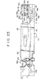
- Reference numeral 64 designates a direction lever laterally slidably supported to the lower surface of the chassis 7 at a substantially laterally central portion on the front half side thereof.
- Two restriction pins 65 and 65' project upwardly from an upper surface of the direction lever 64 at right and left rear portions thereof, respectively.
- the restriction pins 65 and 65' are positioned in proximity to control edges 55d and 56d formed at outer edges of the control portions 55a and 56a of the head levers 55 and 56 at the rear ends thereof, respectively, thereby restricting rearward movement of the control portions 55a and 56a.
- Reference numeral 66 designates a circuit board located under the chassis 7.
- a slide switch 67 for selecting a rotational direction of the motor 10 in constant-speed travelling of the magnetic tape is supported on an upper surface of the circuit board 66 at a front right end portion thereof, and a slide pin 67a projects from a front surface of the slide switch 67.
- the slide pin 67a is movable among a neutral position, that is, an intermediate position of a movable range thereof (in a stop mode), a right end position of the movable range (in forward travelling of the magnetic tape), and a left end position of the movable range (in reverse travelling of the magnetic tape).
- Reference numeral 68 designates a projection projecting downward from a front right end portion of the direction lever 64.
- a recess 68a is formed at a lower edge of the projection 68, and the slide pin 67a of the slide switch 67 is engaged with the recess 68a of the projection 68. Accordingly, when the direction lever 64 is moved, the slide pin 67a of the slide switch 67 is moved in the same direction.
- the magnetic tape is travelled in a forward direction wherein it is supplied from a supply reel (not shown) engaged with the S-side reel bed 8 and is wound up on a take-up reel (not shown) engaged with the T-side reel bed 8'.
- the magnetic tape is travelled in a reverse direction wherein it is supplied from the take-up reel engaged with the T-side reel bed 8' and is wound up on the supply reel engaged with the S-side reel bed 8.
- the right restriction pin 65 is moved rightward away from the control edge 55d of the control portion 55a of the right head lever 55, and the left restriction 65' is moved rightward to contact the control edge 56d of the control portion 56a of the left head lever 56.
- the seesaw lever 58 is pivoted about the left joint pin 58b in the counterclockwise direction, and the right joint pin 58b only is largely moved rearward. Accordingly, the right head lever 55 is pivoted in the clockwise direction by the rearward movement of the right joint pin 58b engaged with the joint hole 57 of the right head lever 55, and the rear end of the control portion 55a of the right head lever 55 is moved rearward.
- the control edge 55d of the control portion 55a urges the slant inside edge 33a of the front end portion 33 of the right depressed arm 31 of the take-up arm 22 in a right rear direction to thereby pivot the take-up arm 22 in the counterclockwise direction. Accordingly, the left play gear 25' of the take-up arm 22 is brought into mesh with the large gear 9'a of the T-side reel bed 8'. In this condition, when the motor 10 is rotated, the magnetic tape is travelled in the forward direction.
- the seesaw lever 58 is pivoted about the right joint pin 58b in the clockwise direction, and the left joint pin 58b only is largely moved rearward. Accordingly, the left head lever 56 is pivoted in the counterclockwise direction by the rearward movement of the left joint pin 58b engaged with the joint hole 57 of the left head lever 56, and the rear end of the control portion 56a of the left head lever 56 is moved rearward.
- Magnetic heads 69 and 69' are supported on the upper surfaces of the front arms 55b and 56b of the head levers 55 and 56, respectively.
- the control portion 55a or 56a of the head lever 55 or 56 is moved rearward, the magnetic head 69 or 69' is moved to its operative position to contact the magnetic tape.
- the take-up arm 22 is slightly pivoted in such a direction that the play gear 25 or 25' is separated from the large gear 9a or 9'a of the reel bed 8 or 8'.
- the control portion 55a or 56a of the head lever 55 or 56 is kept in the rearward moved condition, the front end portion 33 or 33' of the depressed arm 31 or 31' of the take-up arm 22 is hindered by the rear end portion of the control portion 55a or 56a of the head lever 55 or 56.
- the spring portion 32 or 32' of the depressed arm 31 or 31' is flexed to permit the slight pivotal movement of the take-up arm 22.
- the magnetic head 69 or 69' may read signals recorded in the magnetic tape, thereby establishing the cue condition or the review condition.
- Reference numeral 70 designates a tension spring stretched between the direction lever 64 and the chassis 7, so that the direction lever 64 is normally biased to the left, that is, the reverse position by a resilient force of the tension spring 70.
- Reference numeral 71 designates a direction lock member for locking the direction lever 64 in the right position, that is, in the forward position.
- the direction lock member 71 is pivotably supported at a right front portion 71a thereof to the upper surface of the chassis 7 at a right front portion thereof.
- the direction lock member 71 is integrally formed with a long arm 72, a short arm 73, and a depressed portion 74.
- the long arm 72 projects leftward from a left front portion of the direction lock member 71
- the short arm 73 projects leftward from a left rear portion of the direction lock member 71.
- the depressed portion 74 projects rearward from a right rear portion of the direction lock member 71.
- a pawl 72a projects frontward from a front edge of the long arm 72 at a left end portion thereof.
- the pawl 72a has a slant front edge 72b gently inclined rearward as it approaches a left end thereof.
- a projection 73a is formed on a lower surface of the short arm 72 at a left end portion thereof.
- Reference numeral 75 designates a transversely elongated leaf spring fixed at a rear end portion thereof to the chassis 7.
- the leaf spring 75 is formed at a front portion thereof to form two elastic arms 75a and 75b.
- the lower elastic arm 75a of the leaf spring 75 is in elastic contact with a rear end of the depressed portion 74 of the direction lock member 71 from the right side thereof, thereby normally applying a counterclockwise torque to the direction lock member 71.
- a rising portion 76 is formed to project upwardly from the front edge of the direction lever 64 at a right end portion thereof, and three recesses 77, 78a and 78b are formed on an upper edge of the rising portion 76 so as to be juxtaposed in the lateral direction.
- the recesses 78a and 78b are adapted to selectively engage the pawl 72a of the direction lock member 71, and the recess 77 is adapted to engage a projection 79a of a direction knob 79 which will be hereinafter described.
- the projection 79a is formed on a rear surface of the direction knob 79.
- the projection 79a is inserted through a laterally elongated through hole 45a formed through the front plate 45 of the chassis 7, and a rear end portion of the projection 79a is engaged with the recess 77 of the direction lever 64.
- another projection 79b is formed on an upper surface of the direction knob 79, and a locked portion 79c is formed at an upper end of the projection 79b so as to project rearward.
- the position of the left recess 78a of the direction lever 64 becomes identical with the position of the pawl 72a of the direction lock member 71, and the pawl 72a is brought into engagement with the recess 78a by the torque of the direction lock member 71 applied from the elastic arm 75a of the leaf spring 76. In this way, the direction lever 64 is locked in the forward position.
- the pawl 72a may be forcibly disengaged from the recess 78a by relatively strongly applying a leftward force to the direction knob 79.
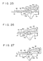
- Reference numeral 80 designates a mode lock member located over the direction lock member 71 and pivotably supported at a right front portion 80a thereof to the same support shaft supporting the direction lock member 71.
- a projection 80b is formed at a left rear portion of the mode lock member 80 so as to project downwardly, and a roller 81 is rotatably supported at a left front portion of the mode lock member 80.
- a depressed portion 80c is formed at a right rear portion of the mode lock member 80 so as to project rearward.
- the upper elastic arm 75b of the leaf spring 75 is in elastic contact with a rear end of the depressed portion 80c of the mode lock member 80 from the right side thereof, thereby normally applying a counterclockwise torque to the mode lock member 80.
- Two laterally elongated holes 82a and 82b are formed at a right end portion of the mode lever 60 so as to be laterally spaced from each other.
- the roller 81 of the mode lock member 80 is brought into engagement with the left hole 82b of the mode lever 60, while when the mode lever 60 is moved to the playback position, the roller 81 of the mode lock member 80 is brought into engagement with the right hole 82a of the mode lever 60.
- click stop of the mode lever 60 is effected by the engagement of the roller 81 with the hole 82a or 82b.
- Reference numeral 83 designates a knob lock member located over the mode lock member 80 and pivotably supported at a right end portion thereof to the same support shaft supporting the direction lock member 71 and the mode lock member 80.
- a controlled projection 83a is formed at a left end portion of the knob lock member 83 so as to project frontward, and a locking projection 83b is also formed at the left end portion of the knob lock member 83 on the just right side of the controlled projection 83a so as to project frontward.
- the locking projection 83b is positioned at a level just higher than that of the controlled projection 83a.
- a controlled pin 83c is formed at a laterally central portion of the knob lock member 83 so as to project downward.
- the controlled pin 83c is positioned between the base portions of the two arms 72 and 73 of the direction lock member 71.
- a counterclockwise torque is normally applied from a spring (not shown) to the knob lock member 83.
- a control projection 84 having a given lateral length is formed at the right end portion of the mode lever 60 so as to project upward from the upper edge thereof.
- the control projection 84 of the mode lever 60 is positioned at the same level as that of the controlled projection 83a of the knob lock member 83. Further, the locking projection 83b of the knob lock member 83 is positioned at a level just higher than an upper edge of the control projection 84.
- the mode lever 60 When the mode lever 60 is in any position other than the record position, a rear surface of the control projection 84 is opposed to the controlled projection 83a of the knob lock member 83, and accordingly the locking projection 83b of the knob lock member 83 is in a retracted position where a front end of the locking projection 83b is positioned on the rear side of a locus of movement of the locked portion 79c of the direction knob 79. Accordingly, the knob lock member 83 does not interfere with the movement of the direction knob 79, that is, the movement of the direction lever 64.
- the left end of the control projection 84 pushes the controlled portion 83a of the knob lock member 83 to clockwise pivot the knob lock member 83 to an unlock position where the locking projection 83b is retracted from the locus of movement of the locked portion 79c of the direction knob 79.
- the direction lock member 71 is clockwise pivoted by the clockwise pivotal movement of the knob lock member 83.
- the controlled pin 83c of the knob lock member 83 is urged rearward by the base portion of the front arm 72 of the direction lock member 71. Accordingly, the knob lock member 83 is pivoted clockwise to unlock the direction knob 79.
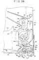
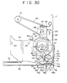
- Reference numeral 85 designates a cam gear rotatably supported to the lower surface of the chassis 7 at a right front portion thereof.
- a plurality of gear teeth 85a are formed on the outer circumference of the cam gear 85, and an annular cam 86 is formed on the upper surface of the cam gear 85 so as to project upward.
- An inner circumferential surface of the cam 86 is formed with a projection 86a. Rotation of the driving gear 13 is normally transmitted through a gear train 87a, 87b and 87c to the cam gear 85.
- the cam gear 85 is always rotated. More specifically, when the magnetic tape is travelled in the forward direction, the cam gear 85 is rotated in the counterclockwise direction, while when the magnetic tape is travelled in the reverse direction, the cam gear 85 is rotated in the clockwise direction.
- Reference numeral 88 designates a support shaft projecting downward from the lower surface of the chassis 7 at a right rear portion thereof.
- the support shaft 88 is formed at a lower end thereof with a flanged spring bearing portion 88a.
- Reference numeral 89 designates a counter pulley rotatably supported to the support shaft 88 at an upper end portion thereof.
- a coil spring 90 is interposed under compression between a lower surface of the counter pulley 89 and the spring bearing portion 88a of the support shaft 88, so that the counter pulley 89 is normally biased upward by a resilient force of the coil spring 90.
- Reference numeral 91 designates a counter pulley integrally formed on a lower surface of the relay gear 26.
- An endless timing belt 92 is wrapped between the counter pulley 91 and the counter pulley 89.
- the counter pulley 89 is kept rotating. More specifically, when the magnetic tape is travelled in the forward direction, the counter pulley 89 is rotated in the clockwise direction, while when the magnetic tape is travelled in the reverse direction, the counter pulley 89 is rotated in the counterclockwise direction.
- Reference numeral 93 designates a plate-like friction arm elongated in the transverse direction.
- a transversely elongated hole 94 is formed through the friction arm 93 at a rear portion thereof, and an upper end portion of the support shaft 88 is inserted through the elongated hole 94. Accordingly, the friction arm 93 is transversely movably supported to the chassis 7.
- a spring bearing portion 95 projects upward from an upper surface of the friction arm 93 at a position behind the elongated hole 94.
- the spring bearing portion 95 is formed in a gently arcuate shape so as to protrude at a central portion thereof.
- Reference numeral 96 designates a torsion spring supported at a base portion thereof to the chassis 7. A free end portion of the torsion spring 96 is in resilient contact with the spring bearing portion 95 of the friction arm 93 from the rear side thereof, so that the friction arm 93 is normally biased frontward by a resilient force of the torsion spring 96.
- the friction arm 93 is formed at a front end thereof to form two arm portions.
- Two projections 97 and 97' each having a teardrop shape as viewed in plan are formed on lower surfaces of the two arm portions of the friction arm 93. That is, the projections 97 and 97' are thin at their rear ends and thick at their front ends.
- the projections 97 and 97' are located within an inside area surrounded by the annular cam 86 of the cam gear 85. When the projection 97 (or 97') is in contact with the projection 86a of the cam 86, the projection 97' (or 97) is in contact with or proximity to a portion of the cam 86 opposite to the projection 86a.
- a depression pin 98 projects upward from a right side edge of the friction arm 93 at a substantially transversely central position thereof.
- the friction arm 93 While the magnetic tape is being travelled, the friction arm 93 is kept swinging under the condition where it is positioned at a front end of a movable range thereof, and when the magnetic tape stops travelling, the friction arm 93 is moved rearward.
- the counter pulley 89 is rotated in the clockwise direction, and accordingly the friction arm 93 kept in elastic contact with the counter pulley 89 by the coil spring 90 receives the clockwise torque from the counter pulley 89. Accordingly, the left projection 97' of the friction arm 93 is kept in contact with a left portion of the cam 86 of the cam gear 85.
- the cam gear 85 is rotated in the counterclockwise direction during rotation of the motor 10. Accordingly, when the projection 86a of the cam 86 comes to the position of the left projection 97', it is brought into contact with the tapered rear end of the left projection 97' to rightward urge the same.
- the friction arm 93 is slightly pivoted in the counterclockwise direction. Thereafter, when the projection 86a is separated from the projection 97', the friction arm 93 is pivoted in the clockwise direction by the clockwise torque received from the counter pulley 89, and the projection 97' comes again to contact with the left portion of the cam 86 other than the projection 86a. In this manner, while the magnetic tape is being travelled in the forward direction, the friction arm 93 is kept swinging.
- the friction arm 93 is slightly pivoted in the clockwise direction. Thereafter, when the projection 86a is separated from the projection 97, the friction arm 93 is pivoted in the counterclockwise direction by the counterclockwise torque received from the counter pulley 89, and the projection 97 comes again to contact with the right portion of the cam 86 other than the projection 86a. In this manner, while the magnetic tape is being travelled in the reverse direction, the friction arm 93 is kept swinging.
- the front surface of the projection 97' is brought into engagement with the projection 86a because the front surface of the projection 97' is substantially flat and it faces the projection 86a. Accordingly, the left projection 97' is urged rearward off to the right to move the friction arm 93 in the same direction as the clockwise rotation of the cam gear 85 proceeds. Thereafter, when the projection 86a comes to the left side of the projection 97', the engagement of the projection 97' with the projection 86a is released. As a result, the friction arm 93 is moved frontward by the resilient force of the torsion spring 96.
- Reference numeral 99 designates a transfer slider transversely movably supported to the chassis 7 at the right end portion thereof.
- a coil spring 100 is stretched between the transfer slider 99 and the chassis 7, so as to normally frontward bias the transfer slider 99.
- a front end portion 99a of the transfer slider 99 projects leftward, and a drawing arm 101 is pivotably supported to the front end portion 99a so as to be pivotable in a given angular range.
- the drawing arm 101 is formed at its front end with a drawing portion 101a projecting upward.
- the drawing arm 101 is pivotable between an automatic shut-off stand-by position where the drawing portion 101a is located on the front side of the projection 80b of the mode lock member 80 and an automatic reverse stand-by position where the drawing portion 101a is located on the front side of the projection 73a of the direction lock member 71.
- the drawing arm 101 is normally biased in the clockwise direction by spring means (not shown).
- a restricting projection 102 is formed at the rear edge of the right portion of the direction lever 64 so as to project upward.
- the restricting projection 102 is located on the left side of the drawing arm 101 in spaced relationship therefrom. In this condition, the drawing arm 101 is located in the automatic shut-off stand-by position mentioned above. Further, when the direction lever 64 is moved to the forward position, the restricting projection 102 rightward urges the drawing arm 101 to pivot the same in the counterclockwise direction to the automatic reverse stand-by position mentioned above.
- a depressed projection 103 is formed on a left side edge of the transfer slider 99 at a substantially central portion thereof so as to project frontward off to the left.
- the depressed projection 103 of the transfer slider 99 is located on a locus of movement of the depression pin 98 of the friction arm 93. That is, when the transfer slider 99 is positioned at a front end of a movable range thereof, the depressed projection 103 is located just behind the depression pin 98 in the condition where the friction arm 99 is positioned at a front end of a movable range thereof.
- the friction arm 93 is moved rearward in association with the rotation of the cam gear 85, and the depression pin 98 of the friction arm 93 rearward urges the depressed projection 103 of the transfer slider 99. Accordingly, the transfer slider 99 is moved rearward against a tensile force of the coil spring 100, and the drawing arm 101 connected to the front end portion 99a of the transfer arm 99 is also moved rearward.
- the drawing arm 101 is pivoted in the counterclockwise direction by the restricting projection 102 to keep the automatic reverse stand-by position where the drawing portion 101a is located on the front side of the projection 73a of the direction lock member 71. Accordingly, when the drawing arm 101 is moved rearward as mentioned above, the drawing portion 101a of the drawing arm 101 rearward draws the projection 73a of the direction lock member 71. Accordingly, the direction lock member 71 is pivoted in the clockwise direction against the resilient force of the elastic arm 75a of the leaf spring 75, and the pawl 72a of the direction lock member 71 is therefore disengaged from the recess 78a of the direction lever 64.
- the knob lock member 83 is also pivoted in the counterclockwise direction in association with the counterclockwise pivotal movement of the direction lock member 71.
- the direction knob 79 in the forward position is unlocked, and the direction lever 64 in the forward position is unlocked, so that the direction lever 64 is moved to the reverse position by the tensile force of the tension spring 70.
- the slide pin 67a engaged with the recess 68a of the direction lever 64 is moved to the reverse position to change the rotational direction of the motor 10.
- the right head lever 55 is returned to its inoperative position, that is, to the front position, and simultaneously the left head lever 56 is moved to its operative position, that is, to the rear position.
- the take-up arm 22 is pivoted in the clockwise direction to bring the play gear 25 into mesh with the large gear 9a of the S-side reel bed 8.
- the magnetic tape starts travelling in the reverse direction.
- the friction arm 93 is moved rearward in association with the rotation of the cam gear 85, and the depression pin 98 of the friction arm 93 therefore urges the depressed projection 103 of the transfer slider 99. Accordingly, the transfer slider 99 is moved rearward against the tensile force of the coil spring 100, and the drawing arm 101 connected to the rear end portion 99a of the transfer slider 99 is also moved rearward.
- the drawing arm 101 is pivoted in the clockwise direction by the spring means not shown to keep the automatic shut-off stand-by position where the drawing portion 101a is located on the front side of the projection 80b of the mode lock member 80. Accordingly, when the drawing arm 101 is moved rearward as mentioned above, the drawing portion 101a of the drawing arm 101 rearward draws the projection 80b of the mode lock member 80. Accordingly, the mode lock member 80 is pivoted in the clockwise direction against the resilient force of the elastic arm 75b of the leaf spring 75, and the roller 81 of the mode lock member 80 is therefore disengaged from the hole 82a or 82b of the mode lever 60. As a result, the mode lever 60 is returned to the neutral position by the resilient force of the centering spring 63. Accordingly, the head lever 56 is returned to its inoperative position, and the motor 10 stops rotating.
- the direction lever 64 may be returned to the forward position by a suitable mechanism such as a mechanism interlocking with unloading operation of the tape cassette from the cassette loading recess 5.
- the direction locking means and the tape end detecting means are not limited to those shown in the above preferred embodiment, but is is only necessary to detect the tape end in the forward mode and then unlock the direction locking means.
Landscapes
- Gear Transmission (AREA)
- Transmission Devices (AREA)
- Adjustment Of The Magnetic Head Position Track Following On Tapes (AREA)
Description
- The present invention relates to a tape recorder, and more particularly to a tape recorder having a reverse function and tape end detecting means.
- In a tape recorder having a reverse function, a torque limiter functioning for tape winding is provided with respect to each of two reel beds.
- Further, in a conventional tape recorder, two magnetic heads for forward travelling and reverse travelling of the tape are mounted on a single arm. When the tape is travelling in a forward direction or a reverse direction, the single arm is pivoted to move one of the magnetic heads accordingly to an operative position where the magnetic head is in contact with the tape.
- Further, in a conventional tape recorder, rotation of a motor is changed into a reciprocating motion by a cam gear, and a direction lever for selecting a tape travelling direction is moved by the reciprocating motion. Furthermore, a gear mechanism and a plunger for starting the movement of the direction lever by the reciprocating motion are provided, and a tape end detecting mechanism is provided in relation to these mechanisms.
- Further, in a conventional tape recorder, a high-speed travelling gear for rotating one of two reel bed gears in mesh therewith at high speeds in establishing a fast forward mode or a rewind mode is provided independently of a gear train for travelling the tape at a constant speed in a playback mode or a record mode.
- However, as in the conventional tape recorder wherein the torque limiter is provided with respect to each of the two reel beds, the number of parts increases and the space required by the parts becomes large, causing difficulty in making the tape recorder compact.
- Further, in the conventional tape recorder while the mounting of two magnetic heads on a single arm is effective in reducing the number of parts, it is difficult to completely adjust azimuths of the two magnetic heads. That is, when the azimuth of one of the two magnetic heads is completely adjusted, and thereafter the azimuth of the other magnetic head is adjusted, the azimuth of the magnetic head previously adjusted becomes out of order.
- Further, in the conventional tape recorder, it is necessary to provide, in addition to the cam gear, the gear mechanism and the plunger for starting the movement of the direction lever and also provide a mechanism or the like for relating these mechanisms to the tape end detecting mechanism. Thus, the whole mechanism becomes large and complex.
- Further, in the conventional tape recorder the high-speed travelling gear is provided independently of the constant-speed travelling gear train. Accordingly, it is difficult to make the structure simple and compact.
- Document GB-A-2,148,580 describes a system in which the tape movement direction changes from forward to reverse at the end of a tape. The preamble of
claim 1 is based on the disclosure of this document. - It is an object of the present invention to provide a tape recorder which employs resilient means for normally biasing the direction lever to a reverse position where a reverse mode is established, thereby changing a tape travelling direction only by unlocking the direction lever in a forward position where a forward mode is established, at the tape end in the forward mode.
- According to the present invention there is provided a tape recorder comprising:
- a direction lever adapted to be slid between a first position where a forward mode is established and a second position where a reverse mode is established, in which a tape travels in a direction reverse to the travelling direction of said tape in said forward mode;
- resilient means for resiliently biasing said direction lever;
- direction lever locking means for locking said direction lever; and
- tape end detecting means for unlocking said direction lever locked by said direction lever locking means at the end of said tape in said forward mode; wherein said tape end detecting means comprises:
- a first unlocking member adapted to receive a torque through a friction mechanism and be pivoted;
- a second unlocking member;
- first biasing means for biasing said second unlocking member in a first direction, wherein when said first unlocking member is moved in a second direction, said second unlocking member is moved in a third direction; and
- a cam gear adapted to receive a torque of a motor and be rotated; characterised in that:
- said resilient means is arranged to bias said direction lever to said second position;
- said direction lever locking means is arranged to lock said direction lever in said first position;
- said first unlocking member is adapted to receive a torque of a reel bed in a forward or reverse direction and be pivoted according to the rotational direction of said reel bed, and is linearly movable;
- said second unlocking member is adapted to be linearly moved;
- said cam gear is adapted to receive the torque of the motor in a forward or reverse direction and be rotated according to the rotational direction of said motor; in that
- when said reel bed is in rotation, said cam gear intermittently pivots said first unlocking member in a direction reverse to that of said torque received, while when said reel bed stops rotating, said cam gear moves said first unlocking member in said second direction, thereby moving said second unlocking member in said third direction to function as a trigger at the tape end; and by further comprising
- second biasing means for biasing said first unlocking member in a fourth direction.
-
- In the tape recorder of the present invention, as the direction lever is normally biased by the resilient means, the direction lever can be moved by a resilient force of the resilient means to the reverse position where the reverse mode is established, only by unlocking the direction lever in the forward position where the forward mode is established at the tape end in the forward mode. Accordingly, a structure for changing a tape travelling direction can be made simple and compact.
- The invention will be more fully understood from the following detailed description given by way of example and with reference to the accompanying drawings, in which:-
- Fig. 1 is a perspective view of a tape recorder according to the present invention under the condition where a cassette lid is opened to show an open condition of a cassette loading portion of the tape recorder;
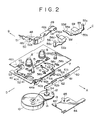
- Fig. 2 is an exploded perspective view of a mechanism portion of the tape recorder as a whole;
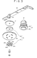
- Fig. 3 is an exploded perspective view illustrating a fast forward/rewind mode select slider, an intermediate gear and a limiter gear with a peripheral portion thereof;
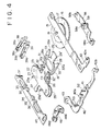
- Fig. 4 is an exploded perspective view illustrating play gears, the intermediate gear and other peripheral members associated therewith;
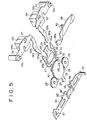
- Fig. 5 is an exploded perspective view illustrating the play gears and other peripheral members associated therewith;
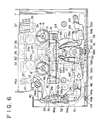
- Fig. 6 is a plan view of the mechanism portion;
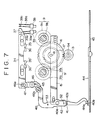
- Fig. 7 is a plan view illustrating a neutral condition of a mechanism for establishing a high-speed travelling mode;
- Fig. 8 is a plan view similar to Fig. 7, illustrating a rewind condition;
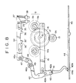
- Fig. 9 is a plan view similar to Fig. 7, illustrating a fast forward condition;
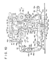
- Fig. 10 is a plan view illustrating a forward playback condition;
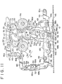
- Fig. 11 is a plan view illustrating a forward record condition;
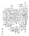
- Fig. 12 is a plan view illustrating a reverse playback condition;
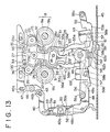
- Fig. 13 is a plan view illustrating a reverse record condition;
- Fig. 14 is a plan view illustrating a cue condition;
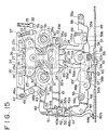
- Fig. 15 is a plan view illustrating a review condition;
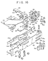
- Fig. 16 is an exploded perspective view illustrating various operation levers and lock mechanisms associated therewith;
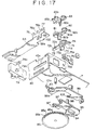
- Fig. 17 is an exploded perspective view illustrating a direction lever, a lock member therefor, and a tape end detecting mechanism;
- Fig. 18 is a partially exploded perspective view of a mechanism for transmitting a torque to the tape end detecting mechanism;
- Fig. 19 is an enlarged elevational view illustrating the lock mechanisms for the various operation levers;
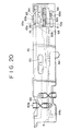
- Fig. 20 is an elevational view illustrating a stop condition;
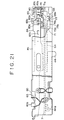
- Fig. 21 is a partially cutaway elevational view illustrating a forward playback condition;
- Fig. 22 is a view similar to Fig. 21, illustrating a reverse playback condition;
- Fig. 23 is a view similar to Fig. 21, illustrating a forward record condition;
- Fig. 24 is an enlarged plan view illustrating the tape end detecting mechanism;
- Fig. 25 is an enlarged plan view illustrating a knob lock member in a playback condition;
- Fig. 26 is a view similar to Fig. 25, illustrating a forward record condition;
- Fig. 27 is a view similar to Fig. 25, illustrating a reverse record condition;
- Fig. 28 is a plan view illustrating a condition of the tape end detecting mechanism in a forward playback condition;
- Fig. 29 is a plan view similar to Fig. 28, illustrating another condition of the tape end detecting mechanism;
- Fig. 30 is a plan view illustrating the tape end detecting mechanism when a magnetic tape stops travelling in a forward playback condition;
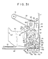
- Fig. 31 is a plan view of an essential part, illustrating an operation for unlocking the direction lever at the tape end in a forward playback condition;
- Fig. 32 is a plan view of an essential part, illustrating an operation for moving the direction lever to a reverse position at the tape end in a forward playback condition;
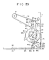
- Fig. 33 is a plan view illustrating a condition of the tape end detecting mechanism in a reverse playback condition;
- Fig. 34 is a plan view similar to Fig. 33, illustrating another condition of the tape end detecting mechanism;
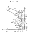
- Fig. 35 is a plan view of the tape end detecting mechanism when the magnetic tape stops travelling at the tape end in a reverse playback condition;
- Fig. 36 is a plan view of an essential part, illustrating an operation for unlocking a mode lever at the tape end in a reverse playback condition; and
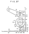
- Fig. 37 is a plan view of an essential part, illustrating an automatic shut-off condition where the mode lever has been returned to a neutral position at the tape end in a reverse playback condition.
-
- A preferred embodiment of the tape recorder according to the present invention will now be described with reference to the accompanying drawings.
-
Reference numeral 1 generally designates a tape recorder according to the present invention. The tape recorder has ahousing 2 and alid 3 for openably closing a cassette insert opening 4 formed on an upper surface of thehousing 2. In an open condition of thelid 3 as shown in Fig. 1, acassette loading recess 5 formed in thehousing 2 is opened through the cassette insert opening 4 to the outside of thehousing 2, so that atape cassette 6 can be loaded into thecassette loading recess 5 and unloaded therefrom. -
Reference numeral 7 designates a chassis mounted in thehousing 2. Thecassette loading recess 5 is defined by an upper surface of thechassis 7 and an inner surface of thehousing 2. - Two
reel beds 8 and 8' are provided in thecassette loading recess 5 so as to be rotatably supported to thechassis 7 and be spaced apart from each other in a lateral direction (as depicted by arrows C and D in Fig. 1). Two reel bed gears 9 and 9' respectively integral with thereel beds 8 and 8' are located under thechassis 7. Thereel bed gear 9 is composed of alarge gear 9a and asmall gear 9b integral with each other. Similarly, the reel bed gear 9' is composed of a large gear 9'a and a small gear 9'b integral with each other. -
Reference numeral 10 designates a motor fixed under thechassis 7 at a left position thereof (on the side depicted by arrow D in Fig. 2). A pulley 11 is fixed to arotating shaft 10a of themotor 10. -
Reference numeral 12 designates a pulley rotatably supported under thechassis 7 at a substantially central position on the front side thereof (on the side depicted by arrow A in Fig. 2). Asmall driving gear 13 is integrally formed on an upper surface of thepulley 12 at a central portion thereof. Anendless belt 14 is wrapped between thepulley 12 and the pulley 11 fixed to therotating shaft 10a of themotor 10. Accordingly, when themotor 10 is rotated, thepulley 12 is rotated in the same direction. -
Reference numeral 15 designates a fast forward/rewind mode select slider (which will be hereinafter referred to as FR slider) elongated in the lateral direction. TheFR slider 15 is laterally slidably supported to thechassis 7 at a central portion thereof in respect of a transverse direction (as depicted by arrow A and B in Fig. 2). -
Reference numeral 16 designates an intermediate gear rotatably supported to asupport shaft 18 vertically extending under theFR slider 15. Theintermediate gear 16 normally meshes thedriving gear 13. -
Reference numeral 17 designates a limiter gear rotatably supported to thesupport shaft 18 over theintermediate gear 16. - A
torque limiter 19 is interposed between theintermediate gear 16 and thelimiter gear 17. Thetorque limiter 19 is composed of afriction disk 20 formed of a material having a large coefficient of friction, such as a felt, and apresser spring 21 for pressing theintermediate gear 16 against thelimiter gear 17 through thefriction disk 20. - The
presser spring 21 is formed of a leaf spring material, and it is constituted of acentral disk 21a and a plurality of L-shapedarms 21b projecting from an outer circumference of thecentral disk 21a and then extending along the outer circumference thereof. A free end of eacharm 21b is slightly bent upwardly. Thecentral disk 21a of thepresser spring 21 is centrally mounted on thesupport shaft 18 at a lower end thereof, and the free ends of thearms 21b of thepresser spring 21 resiliently urges a lower surface of theintermediate gear 16. Thus, theintermediate gear 16 is normally biased upwardly by thepresser spring 21 and is pressed against thelimiter gear 17 through thefriction disk 20. - Accordingly, when the
intermediate gear 16 is rotated, thelimiter gear 17 is also rotated together with theintermediate gear 16. However, when a large load is applied to thelimiter gear 17, slip occurs between thefriction disk 20 and thelimiter gear 17. - When the
FR slider 15 is moved to the left, theintermediate gear 16 is also moved to the left together with theFR slider 15 to come into mesh with the small gear 9'b of the take-up side reel bed gear 9' (which will be hereinafter referred to as T-side reel bed gear 9') of the take-up side reel bed 8' (which will be hereinafter referred to as T-side reel bed 8') and rotate the T-side reel bed 8' in a tape winding direction at high speeds. In contrast, when theFR slider 15 is moved to the right, theintermediate gear 16 is also moved to the right together with theFR slider 15 to come into mesh with thesmall gear 9b of the supply side reel bed gear 9 (which will be hereinafter referred to as S-side reel bed gear 9) of the supply side reel bed 8 (which will be hereinafter referred to as S-side reel bed 8) and rotate the S-side reel bed 8 in a tape winding direction at high speeds. -
Reference numeral 22 designates a take-up arm pivotably supported under thechassis 7 on the rear side at a substantially laterally central position thereof. The take-uparm 22 is formed of a leaf spring material. - The take-up
arm 22 has a plate-likegear supporting portion 23 elongated in the lateral direction. Thegear supporting portion 23 is pivotably supported at a laterally central position thereof on the front side to asupport shaft 24 extending vertically downwardly from thechassis 7. Two play gears 25 and 25' are rotatably supported under thegear supporting portion 23 at right and left end portions thereof, respectively. - Two
small projections gear supporting portion 23 on the rear side at laterally spaced positions thereof. -
Reference numeral 26 designates a relay gear rotatably supported to thesupport shaft 24 under the take-uparm 22. Therelay gear 26 normally meshes thelimiter gear 17 and the play gears 25 and 25'. - A restricted
portion 27 projects rearward from a rear edge of thegear supporting portion 23 at a laterally central position thereof. - A restricting
portion 28 projects frontward from a front edge of thegear supporting portion 23 at a laterally central position thereof. Twoprojections 29 and 29' are formed at a front end of the restrictingportion 28 so as to project rightward and leftward, respectively. - A generally transversely central portion of the restricting
portion 28 is formed as anoval portion 28a. Theoval portion 28a is formed with an oval throughhole 30 elongated laterally. Thesupport shaft 18 supporting theintermediate gear 16 and thelimiter gear 17 is inserted through the oval throughhole 30, so that lateral slide of theFR slider 15 and pivotal movement of the take-uparm 22 are permitted. - Two
depressed arms gear supporting portion 23 at right and left positions spaced from a rear end of the restrictingportion 28. Thedepressed arms portion 28 and terminate at positions just behind the front end of the restrictingportion 28. - Rear end portions of the
depressed arms spring portions 32 and 32', respectively. The remaining portions of thedepressed arms spring portions 32 and 32' extend frontward along the right and left side edges of theoval portion 28a with a fixed space, respectively.Front end portions 33 and 33' of thedepressed arms edges 33a and 33'a opposed to the right and left side edges of the front end portion of the restrictingportion 28 so as to come away from the restrictingportion 28 more as they extend frontward. -
Reference numeral 34 designates a restricting slider laterally slidably supported under thechassis 7 along the rear end thereof. Twodepressing portions 35 and 35' project from a front edge of the restrictingslider 34 at right and left positions spaced laterally, respectively. Thedepressing portions 35 and 35' are formed at their front central positions with V-shapedrecesses 36 and 36', respectively. - In a central position of a movable range of the restricting
slider 34, that is, in a neutral position of the restrictingslider 34, when the take-uparm 22 is pivoted, theprojection 23a or 23'a is brought into engagement with therecess 36 or 36' of thedepressing portion 35 or 35' of the restrictingslider 34. Accordingly, the take-uparm 22 is allowed to be pivoted until theplay gear large gear 9a or 9'a of thereel bed 8 or 8'. - In such a condition that the take-up
arm 22 is pivoted to bring theplay gear large gear 9a or 9'a of thereel bed 8 or 8', a play mode for carrying out record or playback is established. In the play mode, a magnetic tape (not shown) is travelled at a constant speed, and is wound up on a tape reel (not shown) engaged with the T-side reel bed 8' (in a normal play mode) or on another tape reel (not shown) engaged with the S-side reel bed 8 (in a reverse play mode). - In travelling the magnetic tape at high speeds to establish a cue/review condition or a fast forward/rewind condition, the restricting
slider 34 is moved from the neutral position to the left (in the cue condition or the fast forward condition) or to the right (in the review condition or the rewind condition). In particular, when the restrictingslider 34 is moved in a playback condition to establish the cue/review condition, a front surface of thedepressing portion 35 or 35' of the restrictingslider 34 adjacent to therecess 36 or 36' depresses theprojection 23a or 23'a of the take-uparm 22 in which theplay gear large gear 9a or 9'a of thereel bed 8 or 8', and pivots the take-uparm 22 to separate theplay gear large gear 9a or 9'a. - More specifically, when the
FR slider 15 is moved to the left in the playback condition, the restrictingslider 34 is moved from the neutral position to the left by an interlocking mechanism which will be hereinafter described. Accordingly, the take-uparm 22 is pivoted to bring theplay gear large gear 9a or 9'a of thereel bed 8 or 8'. Further, theintermediate gear 16 is brought into mesh with the small gear 9'b of the T-side reel bed 8' by the leftward movement of theFR slider 15. Accordingly, the T-side reel bed 8' is rotated at high speeds in a tape winding direction. In this way, the cue condition is established. - In contrast, when the
FR slider 15 is moved to the right in the playback condition, the restrictingslider 34 is moved from the neutral position to the right by the interlocking mechanism. Accordingly, the take-uparm 22 is pivoted to bring theplay gear large gear 9a or 9'a of thereel bed 8 or 8'. Further, theintermediate gear 16 is brought into mesh with thesmall gear 9b of the S-side reel bed 8 by the rightward movement of theFR slider 15. Accordingly, the S-side reel bed 8 is rotated at high speeds in a tape winding direction. In this way, the review condition is established. - A
switch operating pin 37 projects downwardly from a lower surface of the restrictingslider 34 at a right end thereof. -
Reference numerals motor 10. The leaf switches 38 and 39 are fixed to the lower surface of thechassis 7. The leaf switches 38 and 39 have twocontact arms 38a and twocontact arms 39a, respectively. Free ends of thecontact arms switch operating pin 37. That is, in the neutral position of the restrictingslider 34, the free ends of thecontact arms 38a are located on the right side of theswitch operating pin 37 in spaced relationship therefrom, and the free ends of thecontact arms 39a are located on the left side of theswitch operating pin 37 in spaced relationship therefrom. - Accordingly, when the restricting
slider 34 is moved to the left, theswitch operating pin 37 pushes the free ends of thecontact arms 39a of theleft leaf switch 39 to bring them into contact with each other, thereby rotating themotor 10 in a direction corresponding to the tape winding direction of the T-side reel bed 8'. In contrast, when the restrictingslider 34 is moved to the right, theswitch operating pin 37 pushes the free ends of thecontact arms 38a of theright leaf switch 38 to bring them into contact with each other, thereby rotating themotor 10 in a direction corresponding to the tape winding direction of the S-side reel bed 8. -
Reference numeral 40 designates a substantially L-shaped interlocking arm pivotably supported at a substantially transversely central position thereof to a left end portion of thechassis 7. A rectangularjoint hole 41 is formed through the interlockingarm 40 at a position before apivot 40a of the interlockingarm 40. TheFR slider 15 is formed at its left end with aprojection 42 projecting frontward, and ajoint pin 42a is formed to project upwardly from an upper surface of theprojection 42 at a front end portion thereof. Thejoint pin 42a of theFR slider 15 is slidably engaged with thejoint hole 41 of the interlockingarm 40. - Further, a
joint hole 43 elongated obliquely is formed through the interlockingarm 40 at a rear end portion thereof. -
Reference numeral 44 designates a fast forward/rewind mode select lever (which will be hereinafter referred to as FR lever) laterally slidably supported to afront plate 45 provided on the front edge of thechassis 7. Ajoint hole 44a is formed through theFR lever 44 at a left end portion thereof. Afront end 40b of the interlockingarm 40 is swingably engaged with thejoint hole 44a of theFR lever 44. - Accordingly, when the
FR lever 44 is slid in the lateral direction, the interlockingarm 40 is pivoted about thepivot 40a owing to the engagement of thefront end 40b with thejoint hole 44a of theFR lever 44. As a result, theFR slider 15 jointed with the interlockingarm 40 is moved laterally by the pivotal movement of the interlockingarm 40. - More specifically, when the
FR lever 44 is moved to the left, the interlockingarm 40 is pivoted in a clockwise direction as viewed in top plan to leftward displace thejoint hole 41 engaged with thejoint pin 42a of theFR slider 15. Accordingly, theFR slider 15 is moved to the left. In contrast, when theFR lever 44 is moved to the right, the interlockingarm 40 is pivoted in a counterclockwise direction as viewed in top plan to rightward displace thejoint hole 41 engaged with thejoint pin 42a of theFR slider 15. Accordingly, theFR slider 15 is moved to the right. -
Reference numeral 46 designates a link pivotably supported at an intermediate portion thereof to thechassis 7 at the rear left portion thereof.Joint pins link 46 at rear and front ends thereof, respectively. - The front
joint pin 46b of thelink 46 is slidably engaged with thejoint hole 43 of the interlockingarm 40, and the rearjoint pin 46a of thelink 46 is slidably engaged with a transversely elongatedjoint hole 47 formed through the restrictingslider 34 at the left end portion thereof. - Accordingly, when the
FR lever 44 is slid laterally, the interlockingarm 40 is pivoted, and the restrictingslider 34 is slid laterally through thelink 46. - Further, when the
FR lever 44 is moved from a stop mode to the left or the right, a fast forward more or a rewind mode is established. - That is, as mentioned previously, when the
FR lever 44 is moved to the left, theFR slider 15 is moved to the left through the interlockingarm 40 to bring theintermediate gear 16 into mesh with the small gear 9'b of the T-side reel bed 8'. At the same time, the restrictingslider 34 is moved to the left through the interlockingarm 40 and thelink 46 to thereby bring thecontact arms 39a of theleft switch 39 into contact with each other through theswitch operating switch 37. As a result, themotor 10 is rotated in such a direction as to rotate the T-side reel bed 8' in the tape winding direction. Thus, the fast forward mode is established. - In contrast, when the
FR lever 44 is moved to the right, theFR slider 15 is moved to the right through the interlockingarm 40 to bring theintermediate gear 16 into mesh with thesmall gear 9b of the S-side reel bed 8. At the same time, the restrictingslider 34 is moved to the right through the interlockingarm 40 and thelink 46 to thereby bring thecontact arms 38a of theleaf switch 38 into contact with each other through theswitch operating pin 37. As a result, themotor 10 is rotated in such a direction as to rotate the S-side reel bed 8 in the tape winding direction. Thus, the rewind mode is established. -
Reference numeral 48 designates a substantially L-shaped pinch roller lever pivotably supported at a bent portion thereof to the upper surface of thechassis 7 at a left front position thereof. Thepinch roller lever 48 is generally composed of afront arm 48a extending laterally and aleft arm 48b extending transversely. Apinch roller 49 is rotatably supported to thefront arm 48a at a right end portion thereof. - Further, two rectangular
joint holes left arm 48b of thepinch roller lever 48 at a rear half portion thereof so as to be transversely spaced from each other. Right edges 50a and 51a of thejoint holes - Two
projections arm 40 at front and rear positions spaced from each other on the opposite sides of thepivot 40a. Thefront projection 52 is displaceably received in the frontjoint hole 50 of thepinch roller lever 48, and therear projection 53 is displaceably received in the rearjoint hole 51 of thepinch roller lever 48. -
Reference numeral 54 designates a capstan fixed at a lower end portion thereof to thepulley 12 and thedriving gear 13. Most of thecapstan 54 projects upwardly from the upper surface of thechassis 7. - When the interlocking
arm 40 is pivoted in the counterclockwise direction, thefront projection 52 of the interlockingarm 40 rightward pushes thedepressed edge 50a of the frontjoint hole 50 of thepinch roller lever 48. Accordingly, thepinch roller lever 48 is slightly pivoted in the clockwise direction to thereby bring thepinch roller 49 into separation from thecapstan 54. At this time, therear projection 53 of the interlockingarm 40 is moved leftward in the rearjoint hole 51 of thepinch roller lever 48. Since this leftward movement of therear projection 53 is effected in the rearjoint hole 51, the clockwise pivotal movement of thepinch roller lever 48 is not hindered. - In contrast, when the interlocking
arm 40 is pivoted in the clockwise direction, therear projection 53 of the interlockingarm 40 rightward pushes the depressed edge 51a of the rearjoint hole 51 of thepinch roller lever 48. Accordingly, thepinch roller lever 48 is slightly pivoted in the clockwise direction to thereby bring thepinch roller 49 into separation from thecapstan 54. At this time, thefront projection 52 is moved leftward in the frontjoint hole 50 of thepinch roller lever 48. Since this leftward movement of thefront projection 52 is effected in the frontjoint hole 50, the clockwise pivotal movement of thepinch roller lever 48 is not hindered. - Accordingly, when the
FR lever 44 is operated in the play mode to establish the cue condition or the review condition, thepinch roller 49 is separated from thecapstan 54 to enable the magnetic tape to be travelled at high speeds. -
Reference numerals pivots chassis 7, respectively. The head levers 55 and 56 respectively havecontrol portions chassis 7 on the front half side thereof so as to be opposed to each other, and also respectively havefront arms control portions pivots front arm 55b of theright head lever 55 and at the left end of thefront arm 56b of theleft head lever 56, respectively. Two laterally elongatedjoint holes 57 are formed through thefront arms -
Reference numeral 58 designates a seesaw lever transversely movably and pivotably supported at a laterally central position thereof to a laterally central position of thechassis 7 at the front end portion thereof. Asupport shaft 58a projects upwardly from an upper surface of theseesaw lever 58 at the laterally central portion thereof, and aroller 59 is rotatably supported to thesupport shaft 58a. Further, twojoint pins 58b project upwardly from the upper surface of theseesaw lever 58 at the right and left end portions thereof. - The joint pins 58b of the
seesaw lever 58 are slidably engaged with thejoint holes 57 of the head levers 55 and 56, respectively. -
Reference numeral 60 designates a mode lever for selecting a playback mode or a record mode. Themode lever 60 is laterally slidably supported to thefront plate 45 of thechassis 7. Twocams mode lever 60 at a laterally central portion thereof so as to be laterally slightly spaced from each other. Rear edges of thecams slant edges - The
mode lever 60 is movable among a neutral position, a playback position on the left side of the neutral position, and a record position on the right side of the neutral position.Reference numeral 63 designates a U-shaped centering spring fixed at a base portion thereof to thefront plate 45 of thechassis 7. Two arms of the U-shaped centeringspring 63 are elastically engaged with right and left edges of aprojection 60a formed at an upper edge of themode lever 60, respectively, so as to apply a return force to themode lever 60 to be returned to the neutral position. - When the
mode lever 60 is in an intermediate position of a movable range thereof, that is, in the neutral position, theroller 59 of theseesaw lever 58 is positioned between both thecams - When the
mode lever 60 is moved from the neutral position to the left (in the playback mode) or to the right (in the record mode), theslant edge cam roller 59 of theseesaw lever 58 to thereby rearward move thesupport shaft 58a supporting theroller 59 of theseesaw lever 58. Thereafter, thehold edge 61b or 62b of thecam roller 59, and theroller 59 is stably positioned in contact with thehold edge 61b or 62. This position is an advance position of theseesaw lever 58. - Further, when the
mode lever 60 is moved to the right (i.e., the record position), themotor 10 starts rotating and a record circuit (not shown) is operated, thus establishing the record mode. In contrast, when themode lever 60 is moved to the left (i.e., the playback position), themotor 10 starts rotating and a playback circuit (not shown) is operated, thus establishing the playback mode. -
Reference numeral 64 designates a direction lever laterally slidably supported to the lower surface of thechassis 7 at a substantially laterally central portion on the front half side thereof. Two restriction pins 65 and 65' project upwardly from an upper surface of thedirection lever 64 at right and left rear portions thereof, respectively. - When the
direction lever 64 is in an intermediate position of a movable range thereof, that is, in a neutral position, the restriction pins 65 and 65' are positioned in proximity to controledges control portions control portions -
Reference numeral 66 designates a circuit board located under thechassis 7. Aslide switch 67 for selecting a rotational direction of themotor 10 in constant-speed travelling of the magnetic tape is supported on an upper surface of thecircuit board 66 at a front right end portion thereof, and aslide pin 67a projects from a front surface of theslide switch 67. Theslide pin 67a is movable among a neutral position, that is, an intermediate position of a movable range thereof (in a stop mode), a right end position of the movable range (in forward travelling of the magnetic tape), and a left end position of the movable range (in reverse travelling of the magnetic tape). -
Reference numeral 68 designates a projection projecting downward from a front right end portion of thedirection lever 64. Arecess 68a is formed at a lower edge of theprojection 68, and theslide pin 67a of theslide switch 67 is engaged with therecess 68a of theprojection 68. Accordingly, when thedirection lever 64 is moved, theslide pin 67a of theslide switch 67 is moved in the same direction. - Accordingly, when the
direction lever 64 is moved to the right, and themode lever 60 is then moved from the neutral position to the left or the right to select the playback mode or the record mode, the magnetic tape is travelled in a forward direction wherein it is supplied from a supply reel (not shown) engaged with the S-side reel bed 8 and is wound up on a take-up reel (not shown) engaged with the T-side reel bed 8'. In contrast, when thedirection lever 64 is moved to the left, and themove lever 60 is then moved from the neutral position to the left or the right to select the playback mode or the record mode, the magnetic tape is travelled in a reverse direction wherein it is supplied from the take-up reel engaged with the T-side reel bed 8' and is wound up on the supply reel engaged with the S-side reel bed 8. - More specifically, when the
direction lever 64 is moved to the right, theright restriction pin 65 is moved rightward away from thecontrol edge 55d of thecontrol portion 55a of theright head lever 55, and the left restriction 65' is moved rightward to contact thecontrol edge 56d of thecontrol portion 56a of theleft head lever 56. - In this condition, when the
mode lever 60 is moved to the playback position (i.e., to the left) or the record position (i.e., to the right), the central portion of theseesaw lever 58 is pushed by thecam mode lever 60 to move rearward, and thejoint pins 58b of theseesaw lever 58 will also be moved rearward. However, since thejoint pins 58b are engaged with thejoint holes 57 of the head levers 55 and 56, respectively, and theleft head lever 56 is restricted from moving rearward by the contact of the left restriction pin 65' of thedirection lever 64 with thecontrol edge 56d, the leftjoint pin 58b engaged with thejoint hole 57 of theleft head lever 56 cannot be moved rearward. Accordingly, theseesaw lever 58 is pivoted about the leftjoint pin 58b in the counterclockwise direction, and the rightjoint pin 58b only is largely moved rearward. Accordingly, theright head lever 55 is pivoted in the clockwise direction by the rearward movement of the rightjoint pin 58b engaged with thejoint hole 57 of theright head lever 55, and the rear end of thecontrol portion 55a of theright head lever 55 is moved rearward. - When the rear end of the
control portion 55a of theright head lever 55 is moved rearward as mentioned above, thecontrol edge 55d of thecontrol portion 55a urges the slant insideedge 33a of thefront end portion 33 of the rightdepressed arm 31 of the take-uparm 22 in a right rear direction to thereby pivot the take-uparm 22 in the counterclockwise direction. Accordingly, theleft play gear 25' of the take-uparm 22 is brought into mesh with the large gear 9'a of the T-side reel bed 8'. In this condition, when themotor 10 is rotated, the magnetic tape is travelled in the forward direction. - In contrast, when the
direction lever 64 is moved to the left, the left restriction pin 65' is moved rightward away from thecontrol edge 56d of thecontrol portion 56a of theleft head lever 56, and theright restriction 65 is moved rightward to contact thecontrol edge 55d of thecontrol portion 55a of theright head lever 55. - In this condition, when the
mode lever 60 is moved to the playback position (i.e., to the left) or the record position (i.e., to the right), the central portion of theseesaw lever 58 is pushed by thecam mode lever 60 to move rearward, and thejoint pins 58b of theseesaw lever 58 will also be moved rearward. However, since thejoint pins 58b are engaged with thejoint holes 57 of the head levers 55 and 56, respectively, and theright head lever 55 is restricted from moving rearward by the contact of theright restriction pin 65 of thedirection lever 64 with thecontrol edge 55d, the rightjoint pin 58b engaged with thejoint hole 57 of theright head lever 55 cannot be moved rearward. Accordingly, theseesaw lever 58 is pivoted about the rightjoint pin 58b in the clockwise direction, and the leftjoint pin 58b only is largely moved rearward. Accordingly, theleft head lever 56 is pivoted in the counterclockwise direction by the rearward movement of the leftjoint pin 58b engaged with thejoint hole 57 of theleft head lever 56, and the rear end of thecontrol portion 56a of theleft head lever 56 is moved rearward. - When the rear end of the
control portion 56a of theleft head lever 56 is moved rearward as mentioned above, thecontrol edge 56d of thecontrol portion 56a urges the slant inside edge 33'a of the front end portion 33' of the leftdepressed arm 31' of the take-uparm 22 in a left rear direction to thereby pivot the take-uparm 22 in the clockwise direction. Accordingly, theright play gear 25 of the take-uparm 22 is brought into mesh with thelarge gear 9a of the S-side reel bed 8. In this condition, when themotor 10 is rotated, the magnetic tape is travelled in the reverse direction. -
Magnetic heads 69 and 69' are supported on the upper surfaces of thefront arms control portion head lever magnetic head 69 or 69' is moved to its operative position to contact the magnetic tape. - In establishing the cue condition or the review condition by moving the
FR lever 44 in the playback condition, the take-uparm 22 is slightly pivoted in such a direction that theplay gear large gear 9a or 9'a of thereel bed 8 or 8'. In this case, since thecontrol portion head lever front end portion 33 or 33' of thedepressed arm arm 22 is hindered by the rear end portion of thecontrol portion head lever spring portion 32 or 32' of thedepressed arm arm 22. - As the
magnetic head 69 or 69' is maintained in the operative position, it may read signals recorded in the magnetic tape, thereby establishing the cue condition or the review condition. -
Reference numeral 70 designates a tension spring stretched between thedirection lever 64 and thechassis 7, so that thedirection lever 64 is normally biased to the left, that is, the reverse position by a resilient force of thetension spring 70. -
Reference numeral 71 designates a direction lock member for locking thedirection lever 64 in the right position, that is, in the forward position. Thedirection lock member 71 is pivotably supported at a rightfront portion 71a thereof to the upper surface of thechassis 7 at a right front portion thereof. - The
direction lock member 71 is integrally formed with along arm 72, ashort arm 73, and adepressed portion 74. Thelong arm 72 projects leftward from a left front portion of thedirection lock member 71, and theshort arm 73 projects leftward from a left rear portion of thedirection lock member 71. Further, thedepressed portion 74 projects rearward from a right rear portion of thedirection lock member 71. - A
pawl 72a projects frontward from a front edge of thelong arm 72 at a left end portion thereof. Thepawl 72a has a slantfront edge 72b gently inclined rearward as it approaches a left end thereof. - A
projection 73a is formed on a lower surface of theshort arm 72 at a left end portion thereof. -
Reference numeral 75 designates a transversely elongated leaf spring fixed at a rear end portion thereof to thechassis 7. Theleaf spring 75 is formed at a front portion thereof to form twoelastic arms elastic arm 75a of theleaf spring 75 is in elastic contact with a rear end of thedepressed portion 74 of thedirection lock member 71 from the right side thereof, thereby normally applying a counterclockwise torque to thedirection lock member 71. - A rising
portion 76 is formed to project upwardly from the front edge of thedirection lever 64 at a right end portion thereof, and threerecesses portion 76 so as to be juxtaposed in the lateral direction. Therecesses pawl 72a of thedirection lock member 71, and therecess 77 is adapted to engage aprojection 79a of adirection knob 79 which will be hereinafter described. - The
projection 79a is formed on a rear surface of thedirection knob 79. Theprojection 79a is inserted through a laterally elongated throughhole 45a formed through thefront plate 45 of thechassis 7, and a rear end portion of theprojection 79a is engaged with therecess 77 of thedirection lever 64. - Further, another
projection 79b is formed on an upper surface of thedirection knob 79, and a lockedportion 79c is formed at an upper end of theprojection 79b so as to project rearward. - When the
direction lever 64 is moved to the forward position, the position of theleft recess 78a of thedirection lever 64 becomes identical with the position of thepawl 72a of thedirection lock member 71, and thepawl 72a is brought into engagement with therecess 78a by the torque of thedirection lock member 71 applied from theelastic arm 75a of theleaf spring 76. In this way, thedirection lever 64 is locked in the forward position. Of course, thepawl 72a may be forcibly disengaged from therecess 78a by relatively strongly applying a leftward force to thedirection knob 79. - When the
pawl 72a of thedirection lock member 71 is disengaged from therecess 78a, thedirection lever 64 is moved to the left by a tensile force of thetension spring 70 to reach the reverse position. - When the
direction lever 64 reaches the reverse position as mentioned above, theright recess 78b of thedirection lever 64 is shifted to receive thepawl 72a of thedirection lock member 71. -
Reference numeral 80 designates a mode lock member located over thedirection lock member 71 and pivotably supported at a rightfront portion 80a thereof to the same support shaft supporting thedirection lock member 71. Aprojection 80b is formed at a left rear portion of themode lock member 80 so as to project downwardly, and aroller 81 is rotatably supported at a left front portion of themode lock member 80. Further, adepressed portion 80c is formed at a right rear portion of themode lock member 80 so as to project rearward. The upperelastic arm 75b of theleaf spring 75 is in elastic contact with a rear end of thedepressed portion 80c of themode lock member 80 from the right side thereof, thereby normally applying a counterclockwise torque to themode lock member 80. - Two laterally
elongated holes mode lever 60 so as to be laterally spaced from each other. When themode lever 60 is moved to the record position, theroller 81 of themode lock member 80 is brought into engagement with theleft hole 82b of themode lever 60, while when themode lever 60 is moved to the playback position, theroller 81 of themode lock member 80 is brought into engagement with theright hole 82a of themode lever 60. In each of the record position and the playback position, click stop of themode lever 60 is effected by the engagement of theroller 81 with thehole -
Reference numeral 83 designates a knob lock member located over themode lock member 80 and pivotably supported at a right end portion thereof to the same support shaft supporting thedirection lock member 71 and themode lock member 80. - A controlled
projection 83a is formed at a left end portion of theknob lock member 83 so as to project frontward, and a lockingprojection 83b is also formed at the left end portion of theknob lock member 83 on the just right side of the controlledprojection 83a so as to project frontward. The lockingprojection 83b is positioned at a level just higher than that of the controlledprojection 83a. - Further, a controlled
pin 83c is formed at a laterally central portion of theknob lock member 83 so as to project downward. The controlledpin 83c is positioned between the base portions of the twoarms direction lock member 71. A counterclockwise torque is normally applied from a spring (not shown) to theknob lock member 83. - A
control projection 84 having a given lateral length is formed at the right end portion of themode lever 60 so as to project upward from the upper edge thereof. Thecontrol projection 84 of themode lever 60 is positioned at the same level as that of the controlledprojection 83a of theknob lock member 83. Further, the lockingprojection 83b of theknob lock member 83 is positioned at a level just higher than an upper edge of thecontrol projection 84. - When the
mode lever 60 is in any position other than the record position, a rear surface of thecontrol projection 84 is opposed to the controlledprojection 83a of theknob lock member 83, and accordingly the lockingprojection 83b of theknob lock member 83 is in a retracted position where a front end of the lockingprojection 83b is positioned on the rear side of a locus of movement of the lockedportion 79c of thedirection knob 79. Accordingly, theknob lock member 83 does not interfere with the movement of thedirection knob 79, that is, the movement of thedirection lever 64. - When the
mode lever 60 is moved to the record position, a left end of thecontrol projection 84 comes to the right side of the controlledprojection 83a of theknob lock member 83. That is, the controlledportion 83a of theknob lock member 83 is counterclockwise pivoted to reach a lock position on the left side of thecontrol projection 84. In this condition, when thedirection lever 64 is in the forward position, the lockingprojection 83b of theknob lock member 83 comes to the left side of the lockedportion 79c of thedirection knob 79, while when thedirection lever 64 is in the reverse position, the lockingprojection 83b of theknob lock member 83 comes to the right side of the lockedportion 79c of thedirection knob 79. Thus, the leftward movement or the rightward movement of thedirection knob 79 is inhibited. - According to this operation, it is prevented that a tape travelling direction is manually changed during recording.
- When the
mode lever 60 is moved from the record position to the left, the left end of thecontrol projection 84 pushes the controlledportion 83a of theknob lock member 83 to clockwise pivot theknob lock member 83 to an unlock position where the lockingprojection 83b is retracted from the locus of movement of the lockedportion 79c of thedirection knob 79. In this case, since there is defined a sufficient space between the controlledpin 83c of theknob lock member 83 and therear arm 73 of thedirection lock member 71, there is no possibility that thedirection lock member 71 is clockwise pivoted by the clockwise pivotal movement of theknob lock member 83. - As will be hereinafter described, when the
direction lock member 71 is pivoted clockwise by an automatic reverse mechanism or an automatic shut-off mechanism, the controlledpin 83c of theknob lock member 83 is urged rearward by the base portion of thefront arm 72 of thedirection lock member 71. Accordingly, theknob lock member 83 is pivoted clockwise to unlock thedirection knob 79. -
Reference numeral 85 designates a cam gear rotatably supported to the lower surface of thechassis 7 at a right front portion thereof. A plurality ofgear teeth 85a are formed on the outer circumference of thecam gear 85, and anannular cam 86 is formed on the upper surface of thecam gear 85 so as to project upward. An inner circumferential surface of thecam 86 is formed with aprojection 86a. Rotation of thedriving gear 13 is normally transmitted through agear train cam gear 85. - Accordingly, while the
motor 10 is in rotation, thecam gear 85 is always rotated. More specifically, when the magnetic tape is travelled in the forward direction, thecam gear 85 is rotated in the counterclockwise direction, while when the magnetic tape is travelled in the reverse direction, thecam gear 85 is rotated in the clockwise direction. -
Reference numeral 88 designates a support shaft projecting downward from the lower surface of thechassis 7 at a right rear portion thereof. Thesupport shaft 88 is formed at a lower end thereof with a flanged spring bearing portion 88a. -
Reference numeral 89 designates a counter pulley rotatably supported to thesupport shaft 88 at an upper end portion thereof. Acoil spring 90 is interposed under compression between a lower surface of thecounter pulley 89 and the spring bearing portion 88a of thesupport shaft 88, so that thecounter pulley 89 is normally biased upward by a resilient force of thecoil spring 90. -
Reference numeral 91 designates a counter pulley integrally formed on a lower surface of therelay gear 26. Anendless timing belt 92 is wrapped between thecounter pulley 91 and thecounter pulley 89. - Accordingly, while the magnetic tape is being travelled, the
counter pulley 89 is kept rotating. More specifically, when the magnetic tape is travelled in the forward direction, thecounter pulley 89 is rotated in the clockwise direction, while when the magnetic tape is travelled in the reverse direction, thecounter pulley 89 is rotated in the counterclockwise direction. - When the magnetic tape is fully supplied from the tape reel, both the
reel beds 8 and 8' become nonrotatable, and therefore therelay gear 26 meshing with the play bears 25 and 25' one of which meshes thelarge gear 9a or 9'a of thereel bed 8 or 8' stops rotating. Accordingly, a large load is applied from therelay gear 26 to thelimiter gear 17 meshing therewith, and therefore slip occurs between thelimiter gear 17 and theintermediate gear 16 elastically contacting therewith through thetorque limiter 19. As a result, thecounter pulley 89 connected through theendless timing belt 92 to thecounter pulley 91 integral with therelay gear 26 stops rotating. -
Reference numeral 93 designates a plate-like friction arm elongated in the transverse direction. A transversely elongatedhole 94 is formed through thefriction arm 93 at a rear portion thereof, and an upper end portion of thesupport shaft 88 is inserted through theelongated hole 94. Accordingly, thefriction arm 93 is transversely movably supported to thechassis 7. - A
spring bearing portion 95 projects upward from an upper surface of thefriction arm 93 at a position behind theelongated hole 94. Thespring bearing portion 95 is formed in a gently arcuate shape so as to protrude at a central portion thereof. -
Reference numeral 96 designates a torsion spring supported at a base portion thereof to thechassis 7. A free end portion of thetorsion spring 96 is in resilient contact with thespring bearing portion 95 of thefriction arm 93 from the rear side thereof, so that thefriction arm 93 is normally biased frontward by a resilient force of thetorsion spring 96. - The
friction arm 93 is formed at a front end thereof to form two arm portions. Twoprojections 97 and 97' each having a teardrop shape as viewed in plan are formed on lower surfaces of the two arm portions of thefriction arm 93. That is, theprojections 97 and 97' are thin at their rear ends and thick at their front ends. Theprojections 97 and 97' are located within an inside area surrounded by theannular cam 86 of thecam gear 85. When the projection 97 (or 97') is in contact with theprojection 86a of thecam 86, the projection 97' (or 97) is in contact with or proximity to a portion of thecam 86 opposite to theprojection 86a. - A
depression pin 98 projects upward from a right side edge of thefriction arm 93 at a substantially transversely central position thereof. - While the magnetic tape is being travelled, the
friction arm 93 is kept swinging under the condition where it is positioned at a front end of a movable range thereof, and when the magnetic tape stops travelling, thefriction arm 93 is moved rearward. - More specifically, when the magnetic tape is travelled in the forward direction, the
counter pulley 89 is rotated in the clockwise direction, and accordingly thefriction arm 93 kept in elastic contact with thecounter pulley 89 by thecoil spring 90 receives the clockwise torque from thecounter pulley 89. Accordingly, the left projection 97' of thefriction arm 93 is kept in contact with a left portion of thecam 86 of thecam gear 85. On the other hand, thecam gear 85 is rotated in the counterclockwise direction during rotation of themotor 10. Accordingly, when theprojection 86a of thecam 86 comes to the position of the left projection 97', it is brought into contact with the tapered rear end of the left projection 97' to rightward urge the same. As a result, thefriction arm 93 is slightly pivoted in the counterclockwise direction. Thereafter, when theprojection 86a is separated from the projection 97', thefriction arm 93 is pivoted in the clockwise direction by the clockwise torque received from thecounter pulley 89, and the projection 97' comes again to contact with the left portion of thecam 86 other than theprojection 86a. In this manner, while the magnetic tape is being travelled in the forward direction, thefriction arm 93 is kept swinging. - When the magnetic head stops travelling in the forward direction, the rotation of the
counter pulley 89 is stopped, and thefriction arm 93 therefore stops receiving the clockwise torque from thecounter pulley 89. In this condition, thecam gear 85 continues to be rotated in the counterclockwise direction. Accordingly, when theprojection 86a of thecam 86 comes to the position of the left projection 97' of thefriction arm 93 to rightward urge the left projection 97', theright projection 97 is also moved rightward to come into contact with a right portion of thecam 86 other than theprojection 86a and keep this position. That is, the front surface of theprojection 97 comes to a position on a locus of movement of theprojection 86a and keeps this position. Thereafter, when theprojection 86a comes to the position of theright projection 97, the front surface of theprojection 97 is brought into engagement with theprojection 86a because the front surface of theprojection 97 is substantially flat and it faces theprojection 86a. Accordingly, theright projection 97 is urged rearward off to the left to move thefriction arm 93 in the same direction as the counterclockwise rotation of thecam gear 85 proceeds. Thereafter, when theprojection 86a comes to the right side of theprojection 97, the engagement of theprojection 97 with theprojection 86a is released. As a result, thefriction arm 93 is moved frontward by the resilient force of thetorsion spring 96. - In contrast, when the magnetic tape is travelled in the reverse direction, the
counter pulley 89 is rotated in the counterclockwise direction, and accordingly thefriction arm 93 kept in elastic contact with thecounter pulley 89 by thecoil spring 90 receives the counterclockwise torque from thecounter pulley 89. Accordingly, theright projection 97 of thefriction arm 93 is kept in contact with a right portion of thecam 86 of thecam gear 85. On the other hand, thecam gear 85 is rotated in the clockwise direction during rotation of themotor 10. Accordingly, when theprojection 86a of thecam 86 comes to the position of theright projection 97, it is brought into contact with the tapered rear end of theright projection 97 to leftward urge the same. As a result, thefriction arm 93 is slightly pivoted in the clockwise direction. Thereafter, when theprojection 86a is separated from theprojection 97, thefriction arm 93 is pivoted in the counterclockwise direction by the counterclockwise torque received from thecounter pulley 89, and theprojection 97 comes again to contact with the right portion of thecam 86 other than theprojection 86a. In this manner, while the magnetic tape is being travelled in the reverse direction, thefriction arm 93 is kept swinging. - When the magnetic head stops travelling in the reverse direction, the rotation of the
counter pulley 89 is stopped, and thefriction arm 93 therefore stops receiving the counterclockwise torque from thecounter pulley 89. In this condition, thecam gear 85 continues to be rotated in the clockwise direction. Accordingly, when theprojection 86a of thecam 86 comes to the position of theright projection 97 of thefriction arm 93 to leftward urge theright projection 97, the left projection 97' is also moved leftward to come into contact with a left portion of thecam 86 other than theprojection 86a and keep this position. That is, the front surface of the projection 97' comes to a position on a locus of movement of theprojection 86a and keeps this position. Thereafter, when theprojection 86a comes to the position of the left projection 97', the front surface of the projection 97' is brought into engagement with theprojection 86a because the front surface of the projection 97' is substantially flat and it faces theprojection 86a. Accordingly, the left projection 97' is urged rearward off to the right to move thefriction arm 93 in the same direction as the clockwise rotation of thecam gear 85 proceeds. Thereafter, when theprojection 86a comes to the left side of the projection 97', the engagement of the projection 97' with theprojection 86a is released. As a result, thefriction arm 93 is moved frontward by the resilient force of thetorsion spring 96. -
Reference numeral 99 designates a transfer slider transversely movably supported to thechassis 7 at the right end portion thereof. Acoil spring 100 is stretched between thetransfer slider 99 and thechassis 7, so as to normally frontward bias thetransfer slider 99. - A
front end portion 99a of thetransfer slider 99 projects leftward, and adrawing arm 101 is pivotably supported to thefront end portion 99a so as to be pivotable in a given angular range. Thedrawing arm 101 is formed at its front end with a drawing portion 101a projecting upward. Thedrawing arm 101 is pivotable between an automatic shut-off stand-by position where the drawing portion 101a is located on the front side of theprojection 80b of themode lock member 80 and an automatic reverse stand-by position where the drawing portion 101a is located on the front side of theprojection 73a of thedirection lock member 71. Thedrawing arm 101 is normally biased in the clockwise direction by spring means (not shown). - A restricting
projection 102 is formed at the rear edge of the right portion of thedirection lever 64 so as to project upward. When thedirection lever 64 is in any position other than the forward position, the restrictingprojection 102 is located on the left side of thedrawing arm 101 in spaced relationship therefrom. In this condition, thedrawing arm 101 is located in the automatic shut-off stand-by position mentioned above. Further, when thedirection lever 64 is moved to the forward position, the restrictingprojection 102 rightward urges thedrawing arm 101 to pivot the same in the counterclockwise direction to the automatic reverse stand-by position mentioned above. - A
depressed projection 103 is formed on a left side edge of thetransfer slider 99 at a substantially central portion thereof so as to project frontward off to the left. Thedepressed projection 103 of thetransfer slider 99 is located on a locus of movement of thedepression pin 98 of thefriction arm 93. That is, when thetransfer slider 99 is positioned at a front end of a movable range thereof, thedepressed projection 103 is located just behind thedepression pin 98 in the condition where thefriction arm 99 is positioned at a front end of a movable range thereof. - The automatic reverse operation or the automatic shut-off operation at the tape end is carried out as follows:
- When the magnetic tape is fully supplied from the supply tape reel during forward travelling of the magnetic tape to reach the tape end, the
play gear 25' meshing with the large gear 9'a of the T-side reel bed 8' stops rotating. Accordingly, therelay gear 26 meshing with theplay gear 25' stops rotating to stop transmission of the clockwise torque applied to thefriction arm 93. - On the other hand, there occurs slip between the
limiter gear 17 and theintermediate gear 16 through thetorque limiter 19, so that themotor 10 continues to rotate. Accordingly, thecam gear 85 continues to be rotated in the counterclockwise direction. - Accordingly, as mentioned previously, the
friction arm 93 is moved rearward in association with the rotation of thecam gear 85, and thedepression pin 98 of thefriction arm 93 rearward urges thedepressed projection 103 of thetransfer slider 99. Accordingly, thetransfer slider 99 is moved rearward against a tensile force of thecoil spring 100, and thedrawing arm 101 connected to thefront end portion 99a of thetransfer arm 99 is also moved rearward. - As mentioned previously, when the magnetic tape is travelled in the forward direction, the
drawing arm 101 is pivoted in the counterclockwise direction by the restrictingprojection 102 to keep the automatic reverse stand-by position where the drawing portion 101a is located on the front side of theprojection 73a of thedirection lock member 71. Accordingly, when thedrawing arm 101 is moved rearward as mentioned above, the drawing portion 101a of thedrawing arm 101 rearward draws theprojection 73a of thedirection lock member 71. Accordingly, thedirection lock member 71 is pivoted in the clockwise direction against the resilient force of theelastic arm 75a of theleaf spring 75, and thepawl 72a of thedirection lock member 71 is therefore disengaged from therecess 78a of thedirection lever 64. At the same time, theknob lock member 83 is also pivoted in the counterclockwise direction in association with the counterclockwise pivotal movement of thedirection lock member 71. As a result, thedirection knob 79 in the forward position is unlocked, and thedirection lever 64 in the forward position is unlocked, so that thedirection lever 64 is moved to the reverse position by the tensile force of thetension spring 70. - When the
direction lever 64 is thus moved to reach the reverse position, theslide pin 67a engaged with therecess 68a of thedirection lever 64 is moved to the reverse position to change the rotational direction of themotor 10. Further, theright head lever 55 is returned to its inoperative position, that is, to the front position, and simultaneously theleft head lever 56 is moved to its operative position, that is, to the rear position. Accordingly, the take-uparm 22 is pivoted in the clockwise direction to bring theplay gear 25 into mesh with thelarge gear 9a of the S-side reel bed 8. Thus, the magnetic tape starts travelling in the reverse direction. - Substantially simultaneously with the above automatic reverse operation, the
friction arm 93 and thetransfer slider 99 are returned to the front position. - Thereafter, when the magnetic tape is fully supplied from the tape reel engaged with the S-
side reel bed 8 in the reverse travelling to reach the tape end, thefriction arm 93 is moved rearward in association with the rotation of thecam gear 85, and thedepression pin 98 of thefriction arm 93 therefore urges thedepressed projection 103 of thetransfer slider 99. Accordingly, thetransfer slider 99 is moved rearward against the tensile force of thecoil spring 100, and thedrawing arm 101 connected to therear end portion 99a of thetransfer slider 99 is also moved rearward. - As mentioned previously, when the magnetic tape is travelled in the reverse direction, the
drawing arm 101 is pivoted in the clockwise direction by the spring means not shown to keep the automatic shut-off stand-by position where the drawing portion 101a is located on the front side of theprojection 80b of themode lock member 80. Accordingly, when thedrawing arm 101 is moved rearward as mentioned above, the drawing portion 101a of thedrawing arm 101 rearward draws theprojection 80b of themode lock member 80. Accordingly, themode lock member 80 is pivoted in the clockwise direction against the resilient force of theelastic arm 75b of theleaf spring 75, and theroller 81 of themode lock member 80 is therefore disengaged from thehole mode lever 60. As a result, themode lever 60 is returned to the neutral position by the resilient force of the centeringspring 63. Accordingly, thehead lever 56 is returned to its inoperative position, and themotor 10 stops rotating. - Thereafter, the
direction lever 64 may be returned to the forward position by a suitable mechanism such as a mechanism interlocking with unloading operation of the tape cassette from thecassette loading recess 5. - It is to be understood that the specific shapes and the structures shown in the above preferred embodiment are merely illustrative and the present invention is not limited to the above preferred embodiment. In particular, the direction locking means and the tape end detecting means are not limited to those shown in the above preferred embodiment, but is is only necessary to detect the tape end in the forward mode and then unlock the direction locking means.
Claims (2)
- A tape recorder comprising:wherein said tape end detecting means comprises:a direction lever (64) adapted to be slid between a first position where a forward mode is established and a second position where a reverse mode is established, in which a tape travels in a direction reverse to the travelling direction of said tape in said forward mode;resilient means (70) for resiliently biasing said direction lever;direction lever locking means (71) for locking said direction lever; andtape end detecting means (101) for unlocking said direction lever locked by said direction lever locking means at the end of said tape in said forward mode;a first unlocking member (93) adapted to receive a torque through a friction mechanism and be pivoted;a second unlocking member (99) ;first biasing means (100) for biasing said second unlocking member in a first direction, wherein when said first unlocking member is moved in a second direction, said second unlocking member is moved in a third direction; anda cam gear (85) adapted to receive a torque of a motor (10) and be rotated; characterised in that:said resilient means (70) is arranged to bias said direction lever to said second position;said direction lever locking means (71) is arranged to lock said direction lever in said first position;said first unlocking member (93) is adapted to receive a torque of a reel bed (8') in a forward or reverse direction and be pivoted according to the rotational direction of said reel bed, and is linearly movable;said second unlocking member (99) is adapted to be linearly moved;said cam gear (85) is adapted to receive the torque of the motor (10) in a forward or reverse direction and be rotated according to the rotational direction of said motor; in thatwhen said reel bed (8') is in rotation, said cam gear (85) intermittently pivots said first unlocking member (93) in a direction reverse to that of said torque received, while when said reel bed stops rotating, said cam gear moves said first unlocking member in said second direction, thereby moving said second unlocking member in said third direction to function as a trigger at the tape end; and by further comprisingsecond biasing means (96) for biasing said first unlocking member in a fourth direction.
- A tape recorder according to claim 1 further comprising:a mode lever (60) adapted to be slid between a third position where a record mode is established and a fourth position where a playback mode is established;a direction lock member (80) adapted to be moved to a lock position where movement of said direction lever is inhibited when said mode lever is in said third position, and be moved to an unlock position where the movement of said direction lever is permitted when said mode lever is in any position other than said third position; anda direction unlocking mechanism (101) for moving said direction lock member to said unlock position at the tape end in said record mode.
Applications Claiming Priority (4)
| Application Number | Priority Date | Filing Date | Title |
|---|---|---|---|
| JP22126591 | 1991-08-07 | ||
| JP3221265A JPH0540924A (en) | 1991-08-07 | 1991-08-07 | Tape recorder |
| JP221265/91 | 1991-08-07 | ||
| EP92307148A EP0527041B1 (en) | 1991-08-07 | 1992-08-05 | Mode changing apparatus for a tape cassette |
Related Parent Applications (2)
| Application Number | Title | Priority Date | Filing Date |
|---|---|---|---|
| EP92307148A Division EP0527041B1 (en) | 1991-08-07 | 1992-08-05 | Mode changing apparatus for a tape cassette |
| EP92307148.4 Division | 1992-08-05 |
Publications (2)
| Publication Number | Publication Date |
|---|---|
| EP0766243A1 EP0766243A1 (en) | 1997-04-02 |
| EP0766243B1 true EP0766243B1 (en) | 2000-05-10 |
Family
ID=16764070
Family Applications (3)
| Application Number | Title | Priority Date | Filing Date |
|---|---|---|---|
| EP96118118A Expired - Lifetime EP0766243B1 (en) | 1991-08-07 | 1992-08-05 | Tape recorder having tape end detecting means |
| EP96118046A Expired - Lifetime EP0766242B1 (en) | 1991-08-07 | 1992-08-05 | Tape recorder |
| EP92307148A Expired - Lifetime EP0527041B1 (en) | 1991-08-07 | 1992-08-05 | Mode changing apparatus for a tape cassette |
Family Applications After (2)
| Application Number | Title | Priority Date | Filing Date |
|---|---|---|---|
| EP96118046A Expired - Lifetime EP0766242B1 (en) | 1991-08-07 | 1992-08-05 | Tape recorder |
| EP92307148A Expired - Lifetime EP0527041B1 (en) | 1991-08-07 | 1992-08-05 | Mode changing apparatus for a tape cassette |
Country Status (4)
| Country | Link |
|---|---|
| US (1) | US5363259A (en) |
| EP (3) | EP0766243B1 (en) |
| JP (1) | JPH0540924A (en) |
| DE (3) | DE69228955T2 (en) |
Families Citing this family (6)
| Publication number | Priority date | Publication date | Assignee | Title |
|---|---|---|---|---|
| WO1995032501A1 (en) * | 1994-05-20 | 1995-11-30 | Sony Corporation | Recording and/or reproducing device using a tape cassette |
| JP2945861B2 (en) * | 1995-11-30 | 1999-09-06 | タナシン電機株式会社 | Operation switching device for tape recorder |
| US6175464B1 (en) * | 1997-10-03 | 2001-01-16 | Mec Co., Ltd. | Autoreverse mechanism |
| WO2000041171A1 (en) * | 1998-12-30 | 2000-07-13 | Daewoo Electronics Co., Ltd. | Cassette tape deck |
| US6313966B1 (en) | 1999-01-12 | 2001-11-06 | Daewoo Electronics Co., Ltd. | Cassette tape rotation control mechanism |
| US6220540B1 (en) * | 2000-03-03 | 2001-04-24 | Mec Co. Ltd. | Mechanism for retaining one tape deck in inoperative position in double cassette tape player |
Family Cites Families (23)
| Publication number | Priority date | Publication date | Assignee | Title |
|---|---|---|---|---|
| US3684209A (en) * | 1969-11-24 | 1972-08-15 | Mitsubishi Electric Corp | Automatic return system for tape recorder |
| JPS528682B1 (en) * | 1970-06-27 | 1977-03-10 | ||
| JPS5552548A (en) * | 1978-10-13 | 1980-04-17 | Olympus Optical Co Ltd | Two-head auto-reverse cassette tape recorder |
| JPS5612A (en) * | 1979-06-13 | 1981-01-06 | Olympus Optical Co Ltd | Cassette tape recorder |
| JPS57138151U (en) * | 1981-02-18 | 1982-08-28 | ||
| US4511939A (en) * | 1981-07-17 | 1985-04-16 | Matsushita Electric Industrial Co., Ltd. | Cassette tape recorder |
| US4564873A (en) * | 1981-10-06 | 1986-01-14 | Mitsubishi Denki Kabushiki Kaisha | Magnetic recording and reproducing apparatus |
| DE3209872A1 (en) * | 1982-03-18 | 1983-09-29 | Blaupunkt-Werke Gmbh, 3200 Hildesheim | Reversing drive of an audio tape apparatus |
| US4626940A (en) * | 1982-06-07 | 1986-12-02 | Olympus Optical Co., Ltd. | Tape recorder with reciprocating magnetic heads |
| JPS5994261A (en) * | 1982-11-19 | 1984-05-30 | Toshiba Corp | Tape recorder device |
| IT1156292B (en) * | 1982-12-10 | 1987-01-28 | Lenco Italia Spa | MULTI-PURPOSE MECHANISM FOR MAGNETIC RECORDING-PLAYING MACHINES, WITH BIDIRECTIONAL READING |
| JPS6066352A (en) * | 1983-09-20 | 1985-04-16 | Sony Corp | Reverse type tape recorder |
| US4551939A (en) * | 1983-09-22 | 1985-11-12 | Kitchens Doyle W | Bass fishing organizer |
| AT382036B (en) * | 1985-02-27 | 1986-12-29 | Philips Nv | RECORDING AND / OR PLAYING DEVICE |
| KR910009298B1 (en) * | 1985-04-17 | 1991-11-09 | 샤프 가부시끼가이샤 | Cassette tape recoder with multiple cassette |
| US4799116A (en) * | 1985-09-09 | 1989-01-17 | Sony Corporation | Apparatus for controlling an auto-reverse tape recorder having a mode-changing mechanism |
| JP2565203B2 (en) * | 1987-06-30 | 1996-12-18 | ソニー株式会社 | Mode switching mechanism for reverse type recording / reproducing apparatus |
| JP2691193B2 (en) * | 1988-08-10 | 1997-12-17 | 株式会社三協精機製作所 | Tape recorder operation switching mechanism |
| DE3836246A1 (en) * | 1988-10-25 | 1990-04-26 | Philips Patentverwaltung | Assembly aid for a switching device on a magnetic tape apparatus |
| US5144507A (en) * | 1989-04-27 | 1992-09-01 | Sony Corporation | Cassette tape recording and/or reproducing apparatus with a single pinch lever assembly |
| JPH0799601B2 (en) * | 1989-05-30 | 1995-10-25 | チューナー株式会社 | Tape player |
| JP2727665B2 (en) * | 1989-06-21 | 1998-03-11 | ソニー株式会社 | Tape player |
| US5276567A (en) * | 1989-10-25 | 1994-01-04 | Tuner Company Limited | Tape player |
-
1991
- 1991-08-07 JP JP3221265A patent/JPH0540924A/en active Pending
-
1992
- 1992-07-29 US US07/921,249 patent/US5363259A/en not_active Expired - Fee Related
- 1992-08-05 EP EP96118118A patent/EP0766243B1/en not_active Expired - Lifetime
- 1992-08-05 DE DE69228955T patent/DE69228955T2/en not_active Expired - Fee Related
- 1992-08-05 EP EP96118046A patent/EP0766242B1/en not_active Expired - Lifetime
- 1992-08-05 DE DE69231044T patent/DE69231044T2/en not_active Expired - Fee Related
- 1992-08-05 DE DE69227953T patent/DE69227953T2/en not_active Expired - Fee Related
- 1992-08-05 EP EP92307148A patent/EP0527041B1/en not_active Expired - Lifetime
Also Published As
| Publication number | Publication date |
|---|---|
| DE69228955D1 (en) | 1999-05-20 |
| EP0766242A1 (en) | 1997-04-02 |
| DE69227953D1 (en) | 1999-02-04 |
| EP0527041A2 (en) | 1993-02-10 |
| JPH0540924A (en) | 1993-02-19 |
| EP0766242B1 (en) | 1999-04-14 |
| EP0527041B1 (en) | 1998-12-23 |
| US5363259A (en) | 1994-11-08 |
| EP0766243A1 (en) | 1997-04-02 |
| DE69231044T2 (en) | 2001-01-11 |
| EP0527041A3 (en) | 1995-02-15 |
| DE69231044D1 (en) | 2000-06-15 |
| DE69228955T2 (en) | 1999-10-21 |
| DE69227953T2 (en) | 1999-07-29 |
Similar Documents
| Publication | Publication Date | Title |
|---|---|---|
| CA1188416A (en) | Cassette tape recording and/or reproducing apparatus | |
| KR940006387B1 (en) | Magetic recording and reproducing device | |
| EP0766243B1 (en) | Tape recorder having tape end detecting means | |
| CA1317579C (en) | Mode-change mechanism for tape recording and/or reproducing apparatus | |
| EP0297806B1 (en) | FF/Rew mechanism for tape recording and/or reproducing apparatus | |
| US5029036A (en) | Normal/reverse mode changing mechanism for tape transport apparatus | |
| GB2197979A (en) | Tape winding direction switch device of cassette tape recorder | |
| US4623946A (en) | Mode changing mechanism for cassette tape recording and/or reproducing apparatus | |
| US4809101A (en) | Automatic stopping mechanism for a tape feeding device | |
| US6512656B1 (en) | Recording and/or reproducing apparatus for a magnetic tape | |
| US4656321A (en) | Three position switch and switching device for a magnetic-tape-cassette apparatus | |
| JPS6230184Y2 (en) | ||
| EP0395364B1 (en) | A cassette tape recording and/or reproducing apparatus | |
| JP3067302B2 (en) | Tape player | |
| KR860001255B1 (en) | Tape recorder | |
| EP0045328B1 (en) | A loading mechanism for a cassette tape recorder | |
| JP3057526B2 (en) | Tape recorder | |
| JPS5918776B2 (en) | Cassette type recording/playback device | |
| CA1161165A (en) | Mode change-over mechanism for a tape recorder | |
| JP2571718B2 (en) | Mode switching device for auto-reverse tape recorder | |
| JPH0516644Y2 (en) | ||
| GB1561448A (en) | Recording and reproducing apparatus | |
| US4541589A (en) | Magnetic recording and reproducing apparatus | |
| JPH0547066A (en) | Tape recorder | |
| JPS6125076Y2 (en) |
Legal Events
| Date | Code | Title | Description |
|---|---|---|---|
| PUAI | Public reference made under article 153(3) epc to a published international application that has entered the european phase |
Free format text: ORIGINAL CODE: 0009012 |
|
| AC | Divisional application: reference to earlier application |
Ref document number: 527041 Country of ref document: EP |
|
| AK | Designated contracting states |
Kind code of ref document: A1 Designated state(s): DE FR GB |
|
| 17P | Request for examination filed |
Effective date: 19970909 |
|
| 17Q | First examination report despatched |
Effective date: 19990423 |
|
| GRAG | Despatch of communication of intention to grant |
Free format text: ORIGINAL CODE: EPIDOS AGRA |
|
| GRAG | Despatch of communication of intention to grant |
Free format text: ORIGINAL CODE: EPIDOS AGRA |
|
| GRAH | Despatch of communication of intention to grant a patent |
Free format text: ORIGINAL CODE: EPIDOS IGRA |
|
| GRAH | Despatch of communication of intention to grant a patent |
Free format text: ORIGINAL CODE: EPIDOS IGRA |
|
| GRAA | (expected) grant |
Free format text: ORIGINAL CODE: 0009210 |
|
| AC | Divisional application: reference to earlier application |
Ref document number: 527041 Country of ref document: EP |
|
| AK | Designated contracting states |
Kind code of ref document: B1 Designated state(s): DE FR GB |
|
| REF | Corresponds to: |
Ref document number: 69231044 Country of ref document: DE Date of ref document: 20000615 |
|
| ET | Fr: translation filed | ||
| PLBE | No opposition filed within time limit |
Free format text: ORIGINAL CODE: 0009261 |
|
| STAA | Information on the status of an ep patent application or granted ep patent |
Free format text: STATUS: NO OPPOSITION FILED WITHIN TIME LIMIT |
|
| 26N | No opposition filed | ||
| PGFP | Annual fee paid to national office [announced via postgrant information from national office to epo] |
Ref country code: DE Payment date: 20010730 Year of fee payment: 10 |
|
| PGFP | Annual fee paid to national office [announced via postgrant information from national office to epo] |
Ref country code: GB Payment date: 20010801 Year of fee payment: 10 |
|
| PGFP | Annual fee paid to national office [announced via postgrant information from national office to epo] |
Ref country code: FR Payment date: 20010810 Year of fee payment: 10 |
|
| REG | Reference to a national code |
Ref country code: GB Ref legal event code: IF02 |
|
| PG25 | Lapsed in a contracting state [announced via postgrant information from national office to epo] |
Ref country code: GB Free format text: LAPSE BECAUSE OF NON-PAYMENT OF DUE FEES Effective date: 20020805 |
|
| PG25 | Lapsed in a contracting state [announced via postgrant information from national office to epo] |
Ref country code: DE Free format text: LAPSE BECAUSE OF NON-PAYMENT OF DUE FEES Effective date: 20030301 |
|
| GBPC | Gb: european patent ceased through non-payment of renewal fee |
Effective date: 20020805 |
|
| PG25 | Lapsed in a contracting state [announced via postgrant information from national office to epo] |
Ref country code: FR Free format text: LAPSE BECAUSE OF NON-PAYMENT OF DUE FEES Effective date: 20030430 |
|
| REG | Reference to a national code |
Ref country code: FR Ref legal event code: ST |