EP0765778B1 - Seat cover for protecting motor car seats - Google Patents
Seat cover for protecting motor car seats Download PDFInfo
- Publication number
- EP0765778B1 EP0765778B1 EP96112580A EP96112580A EP0765778B1 EP 0765778 B1 EP0765778 B1 EP 0765778B1 EP 96112580 A EP96112580 A EP 96112580A EP 96112580 A EP96112580 A EP 96112580A EP 0765778 B1 EP0765778 B1 EP 0765778B1
- Authority
- EP
- European Patent Office
- Prior art keywords
- seat
- seat cover
- foil
- layer
- forming
- Prior art date
- Legal status (The legal status is an assumption and is not a legal conclusion. Google has not performed a legal analysis and makes no representation as to the accuracy of the status listed.)
- Expired - Lifetime
Links
Images
Classifications
-
- B—PERFORMING OPERATIONS; TRANSPORTING
- B60—VEHICLES IN GENERAL
- B60N—SEATS SPECIALLY ADAPTED FOR VEHICLES; VEHICLE PASSENGER ACCOMMODATION NOT OTHERWISE PROVIDED FOR
- B60N2/00—Seats specially adapted for vehicles; Arrangement or mounting of seats in vehicles
- B60N2/58—Seat coverings
- B60N2/60—Removable protective coverings
- B60N2/6018—Removable protective coverings attachments thereof
- B60N2/6063—Removable protective coverings attachments thereof by elastic means
Definitions
- the invention relates to a seat cover for protecting a motor vehicle seat from a double-layer part made of plastic film, in particular one-time purchase for workshops with a continuous, the seat of the seat cushion and the backrest surface the backrest of the seat protective front layer and one with the reserve connected by transverse welding, which in Connection to the front position on the back of the seat forms at least partially receiving first pocket.
- a seat cover of the type described above is from the DE-A-16 30 878 known.
- a Plastic tube cut open by a longitudinal cut. The resulting edges are mutually different removed and folded flat at a distance from the rest of the material of the hose. This creates a flat lying in Areas double-layered web from which the cross-welds individual seat covers can be created.
- the coherent The piece of material of the hose forms the front layer on the one hand and on the other hand a reserve with marginal areas. These marginal areas form the reserve with the attached front layer one pocket each, the first pocket being intended to placed the upper area of the backrest of the motor vehicle seat to become while the second pocket is the free end of the seat cushion can partially spill over if the seat cover is properly is mounted.
- This well-known seat cover is out Made of plastic film.
- the plastic film as a mono film has a low coefficient of friction on both surfaces, is therefore relatively smooth.
- the seat covers can be delivered coiled on rolls, whereby they are separated from one another by a perforation. It it is also possible to have the individual seat covers already at the Separating production from each other and then stacking them, e.g. B. in a carton.
- the Use i.e. when hanging up or pulling over a motor vehicle seat, it is first necessary, at least for the backrest specific pocket to open the seat cover over the backrest and a possibly provided Pull headrest.
- the bag opens due to use a smooth plastic sheet easily, and covering about the motor vehicle seat is comparatively no problem.
- the bag which is shorter, practically only overlaps still the headrest and can be on the side of the protruding Slip the corner areas of the backrest sideways.
- the pocket is higher or longer, then again Opening process harder, and pulling over the backrest and the headrest are difficult, although advantageous this results in a better fit on the backrest.
- the seat covers that are practically placed on the market, in order to take account of the economy, if possible thin film should be made, if only to to minimize the material consumption of plastic. This happens not least from an environmental point of view, because a Temporary protection of a surface with a single cover should burden natural resources as little as possible.
- Such Monofilm seat covers up to 0.013 mm thick have prevailed in the workshops. But just that Using a thin film increases the problems of the Opening the bag.
- the invention has for its object a seat cover Provide the type described above, of which over the On the one hand, the backrest bag can be easily opened and opened Effortlessly with the correct seat on the motor vehicle seat lets, however, on the other hand, even when taking multiple places on the motor vehicle seat protected with the seat cover applied not slipped.
- this is the case of a seat cover as described at the beginning Art achieved in that the front position on the one hand and the reserve, on the other hand, is formed as separate material webs are also connected to each other by longitudinal welding are connected that the web of material forming the front layer coextruded film material with a high coefficient of friction one surface and with a comparatively low coefficient of friction on the other surface and with that high coefficient of friction surface of the reserve is arranged facing, and that the reserve Material web at least on the one facing the front layer Surface has a low coefficient of friction.
- the invention is based on the idea of partially contradicting these To meet demands. It will be a separate first Material web used that the front layer of the seat cover forms. A second web of plastic film is separated used, which forms the reserve. Only those Front sheet forming material web consists of a co-extruded Foil material with a high coefficient of friction on the Motor vehicle seat facing side while the other Surface facing the fitter is smooth is. For the reserve, it is important to use a film, at least on the inside facing the front layer is smooth. This achieves a double function: on the one hand, the areas covered by the Front layer and the back pocket formed easily and effortlessly open, for example by a simple shaking process. This applies regardless of whether the seat cover is packed in batches is placed on the market or wrapped on a roll.
- the inside of the reserve can be very smooth be trained, e.g. B. also with a higher proportion of lubricant than previously known. Also a particularly high or long one designed pocket in the backrest area as it is for different Motor vehicle seats in workshops including headrests with different heights make sense, no longer disturbs the easy opening of the bag.
- the Invention can be applied when the seat cover is only a pocket for the area of the backrest. It is also possible to easily manufacture the seat cover with two pockets and to handle, the second pocket then in the area of Seat cushion is put on.
- the material web forming the reserve can be on both surfaces have a low coefficient of friction. This simplifies the production of the material web forming the reserve and also makes it easier to unfold one, for example multiply folded seat cover. So it is without further possible that the material web forming the reserve a single-layer plastic film, which is then appropriate the same on both sides, relatively low Has coefficient of friction.
- Material web is of a different color.
- the front layer made of a white-colored material web exist while the reserve forming the first pocket from a z. B. there is a colored material web.
- This Different colors set a visual appeal and encourages the user to pull on the seat cover Motor vehicle seat to ensure a proper seat.
- a third separate web of material at least on their surface facing the front layer has low coefficient of friction and to form a the seat cushion at least partially enclosing the second Pocket with the front layer through longitudinal and transverse welds connected is.
- This third separate material web can be made from the same plastic material as the second material web, which forms the first pocket. But it is also possible to Use different foils in the area of the reserve.
- the individual slides can vary depending on the ones you want Properties are trained.
- the third separate material web can also be compared to the first material web forming the front layer in a different color be designed so that this second pocket is easily recognizable is. If the third separate web of material compared to of the material web forming the first reserve in a different color trained, the fitter can already optically the two Differentiate bags from each other, so that, for. B. with different Height of the two pockets, is ensured and it is easy to check whether the generally higher bag for the backrest is created on the backrest and not about in the area of the seat cushion.
- the adhesive surface is even more adhesive than to equip so far without fear that the through Folding the front layer formed heavy or not at all there is more to open.
- the one that forms the front layer Material web on its surface facing the reserve Coefficient of friction of about 1.0 or even> 1.0 and on it the surface facing away from the reserve has a coefficient of friction of about 0.1.
- the material web forming the reserve can have a surface facing the front layer Have coefficients of friction of about 0.01.
- the web of material forming the front layer and the The material web forming the reserve each has a thickness in the range of approximately Have 13 ⁇ .
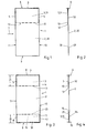
- FIG. 1 the top view of a seat cover 1 is shown.
- the seat cover consists of a front layer 2 and a back layer 3 composed, each separate, separate pieces of film represent. From Fig. 2 is the mutual coverage of Front position 2 and reserve 3 recognizable.
- the reserve 3 forming material piece is with the front layer over two cross welds 4 and 5 and a longitudinal weld 6, wherein the longitudinal weld 6 in Fig. 2 only by an arrow is indicated.
- the seat cover 1 is manufactured in a manner known per se Way by merging the two on the one hand the front position 2 and on the other hand the tracks 3 forming the reserve. This happens in the running direction according to arrow 7.
- the two tracks have free edges 8 and 9 in the running direction according to arrow 7 other edges 10 and 11 extend transversely to the direction of travel according to arrow 7.
- the front layer 2 and the reserve layer 3 can thus be connected to each other so that the connection areas extend along the free edges of the seat cover. It is but it is also possible to shift these connection areas somewhat, for example in the upper area of the front layer of the Pocket 12 into it, in particular in such an area of the Bag 12 on the headrest of the motor vehicle seat too comes to lie. There is no high coefficient of friction here required and by laying the connection area it makes it easier to wind up the seat covers that are attached to each other on the roll.
- the upper area of the front layer 2 forms with the reserve 3 a pocket 12, which is only open at its lower edge 13, while the three remaining sides through the cross welds 4 and 5 and the longitudinal weld 6 is closed.
- This bag 12 is important open before a seat cover 1, as shown in Fig. 5, can be pulled over a motor vehicle seat 14.
- the new seat cover makes it comparatively easier Opening the bag 12 and a facilitated pulling over the Backrest of the motor vehicle seat. This one unloved by the fitter This makes work much easier.
- Another advantage results in a stronger and safer in the opened state as it were immovable hold of the seat cover on the motor vehicle seat, thus the intended protective effect.
- FIG. 3 and 4 is another embodiment of a Seat cover 1 shown, with a front layer 2 and a reserve 3 are provided. These two pieces of material also form the pocket 12 here for the backrest of the Motor vehicle seat 14 is determined. However, it is still one further material web 15 is provided in the lower area, which insofar as the reserve 3 is supplemented. This material web 15 forms together with the lower area of the front layer 2 a second Pocket 16.
- the pocket 16 is by two cross welds 17 and 18 and closed by a longitudinal weld 19 on three sides trained and only open along its upper edge 20.
- the Height 21 of the pocket 12 is suitably larger or longer than that Height 22 of the second pocket 16. In particular, the height of the Pocket 12 twice as long as the height of pocket 16 be trained without the easy opening of the Pocket 12 is affected. Bags 12 and 16 can also have the same height.
- the motor vehicle seat 14 is known to have a seat cushion 23 with a seat 24 and a backrest 25 with a backrest surface 26.
- a headrest 27 is located at the upper end of the backrest 25.
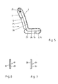
- the material web 28 consists of coextruded film material, in which - as shown - two layers are connected.
- the one Layer has a surface 29 with a low coefficient of friction while the other layer has a surface 30 has a high coefficient of friction.
- the material web can also be coextruded from three layers (or more), then another layer between the two layers shown is arranged. This middle class can help improve Serve tensile strength.
- the material web 28 arranged as shown in Fig. 2, namely so that the surface 30 with the high coefficient of friction the reserve 3 is arranged facing. The same applies to the embodiment of FIGS. 3 and 4.
- Fig. 7 shows a material web 31, which is used to form the reserve 3 is used.
- the material web 31 has a surface 32 with a lower coefficient of friction.
- the other surface too 33 may have a low coefficient of friction.
- the both surfaces 32 and 33 be made equally smooth.
- the Material web 31 is arranged such as this, for example Fig. 2 can be seen, so that in any case a smooth Surface 32 of the front layer 2 is facing. With that lie inside a pocket 12 - and accordingly in a pocket 16 -
- the material webs 15 and 31 can be made of the same material consist.
- the material web 28 can for example white or translucent, while the material web 31 is colored blue, for example.
- the material web 15 can be colored gray. In this case is immediately recognizable which is the pocket 12 that the assigned to the upper region of the backrest 25 and the headrest 27 is.
- the manufacture of the seat covers 1 takes place in such a way that endless material webs 28 and 31 one above the other in the direction of Arrow 7 are guided and thereby achieve a relative position, as indicated in Fig. 1. It is then attached the longitudinal weld 6 along one edge 8 and the Attach the cross welds 4 and 5 so that the material webs 28 and 31 connected to form the pocket 12 are. Then along the edges 10 and 11 either Perforations are arranged when the seat covers 1 are contiguous to be wound on a roll. When a a batch delivery is intended, a separation takes place or cutting off the individual seat covers 1 along the edges 10 and 11, mostly with a subsequent folding process.
- the Material web 15 additionally use. This will be accordingly the material web 31 formed and arranged. Also the Material web 15 has a surface 34 with a low coefficient of friction.
Landscapes
- Engineering & Computer Science (AREA)
- Aviation & Aerospace Engineering (AREA)
- Transportation (AREA)
- Mechanical Engineering (AREA)
- Seats For Vehicles (AREA)
- Vehicle Step Arrangements And Article Storage (AREA)
- Laminated Bodies (AREA)
- Motor Or Generator Frames (AREA)
Abstract
Description
Die Erfindung betrifft einen Sitzbezug zum Schutz eines Kraftfahrzeug-Sitzes aus einem doppellagigen Teil aus Kunststoffolie, insbesondere Einmalbezug für Werkstätten, mit einer durchgehenden, die Sitzfläche des Sitzpolsters und die Rückenlehnenfläche der Rückenlehne des Sitzes schützenden Vorderlage und einer mit der Vorderlage durch Querschweißung verbundenen Rücklage, die in Verbindung mit der Vorderlage eine die Rückenlehne des Sitzes zumindest teilweise aufnehmende erste Tasche bildet.The invention relates to a seat cover for protecting a motor vehicle seat from a double-layer part made of plastic film, in particular one-time purchase for workshops with a continuous, the seat of the seat cushion and the backrest surface the backrest of the seat protective front layer and one with the reserve connected by transverse welding, which in Connection to the front position on the back of the seat forms at least partially receiving first pocket.
Sitzbezüge aus Kunststoffolie werden über Kraftfahrzeug-Sitze gestülpt bzw. gezogen, um eine Verschmutzung des Kraftfahrzeug-Sitzes durch Monteure und andere Personen zu verhindern. Bekannt sind solche Sitzbezüge in ihrer Anwendung in Automobilwerkstätten, wenn an Kraftfahrzeugen eine Inspektion oder Reparatur durchgeführt wird. Bei einer solchen Reparatur kommt es natürlich vor, daß sich der Monteur mehrmals auf den mit dem Sitzbezug geschützten Kraftfahrzeug-Sitz setzt. Bekanntlich kann man sich auf einen Kraftfahrzeug-Sitz nicht direkt von vorne setzen, wie dies bei einem Stuhl möglich ist; die Sitzbewegung erfolgt vielmehr von der Seite her in das Kraftfahrzeug hinein. Dabei besteht die Gefahr, daß der Sitzbezug auf dem Kraftfahrzeug-Sitz verrutscht, so daß dann Oberflächenbereiche des Sitzpolsters und/oder der Rückenlehne ungeschützt sind und beim nächsten Sitzvorgang mit dem u. U. verschmutzten Monteuranzug direkt in Kontakt kommen.Seat covers made of plastic film are made over motor vehicle seats pulled up or pulled to contaminate the motor vehicle seat prevented by fitters and other people. Known are such seat covers in their application in automobile workshops, if an inspection or repair on motor vehicles is carried out. With such a repair, of course, it happens before that the fitter several times on the one with the seat cover protected motor vehicle seat sets. As you know, you can do not sit on a motor vehicle seat directly from the front, how this is possible with a chair; the seat movement takes place rather from the side into the motor vehicle. Here there is a risk that the seat cover on the motor vehicle seat slips, so that then surface areas of the seat cushion and / or the backrest are unprotected and the next Sitting process with the u. U. dirty mechanic suit directly in Come in contact.
Ein Sitzbezug der eingangs beschriebenen Art ist aus der DE-A-16 30 878 bekannt. Bei der Herstellung des Sitzbezuges wird ein Schlauch aus Kunststoffolie durch einen Längsschnitt aufgeschnitten. Die dabei entstehenden Ränder werden voneinander entfernt und flach gefaltet im Abstand auf das übrige Material des Schlauches gelegt. Dabei entsteht eine flach liegende, in Bereichen doppellagige Bahn, aus der durch Querschweißungen die einzelnen Sitzbezüge erstellt werden. Das zusammenhängende Materialstück des Schlauches bildet einerseits die Vorderlage und andererseits mit Randbereichen eine Rücklage. Diese Randbereiche der Rücklage bilden mit der daran hängenden Vorderlage je eine Tasche, wobei die erste Tasche dazu bestimmt ist, im oberen Bereich der Rückenlehne des Kraftfahrzeug-Sitzes plaziert zu werden, während die zweite Tasche das freie Ende des Sitzpolsters teilweise übergreifen kann, wenn der Sitzbezug ordnungsgemäß montiert ist. Dieser bekannte Sitzbezug ist aus Kunststoffolie hergestellt. Die Kunststoffolie als Monofolie besitzt auf beiden Oberflächen einen niedrigen Reibungskoeffizienten, ist also relativ glatt ausgebildet. Die Sitzbezüge können aneinanderhängend auf Rollen gewickelt geliefert werden, wobei sie über eine Perforation voneinander getrennt werden. Es ist aber auch möglich, die einzelnen Sitzbezüge bereits bei der Herstellung voneinander zu trennen und diese dann stapelweise, z. B. in einem Umkarton, in Verkehr zu bringen. Bei der Benutzung, also beim Auflegen bzw. Überziehen über einen Kraftfahrzeug-Sitz, ist es zunächst erforderlich, zumindest die für die Rückenlehne bestimmte Tasche zu öffnen, um den Sitzbezug über die Rückenlehne und eine möglicherweise daran vorgesehene Kopfstütze zu ziehen. Das Öffnen der Tasche gelingt infolge Verwendung einer glatten Kunststoffolie leicht, und das Überziehen über den Kraftfahrzeug-Sitz gestaltet sich vergleichsweise problemlos. Da ein solcher Sitzbezug jedoch auch auf seiner Innenseite, also auf der Seite, die der Sitzfläche des Sitzpolsters und der Rückenlehnenfläche der Rückenlehne zugekehrt ist, einen niedrigen Reibungskoeffizienten aufweist, verändert sich die Lage des Sitzbezuges an dem Kraftfahrzeug-Sitz bei jedem Niedersetzen des Monteurs und bei jeder Bewegung auf dem Kraftfahrzeug-Sitz. Dies ist nachteilig, weil dadurch der Sitzbezug unkontrolliert verrutscht und Bereiche des Sitzes von dem Sitzbezug nicht mehr abgedeckt werden, also ungeschützt sind.A seat cover of the type described above is from the DE-A-16 30 878 known. When manufacturing the seat cover, a Plastic tube cut open by a longitudinal cut. The resulting edges are mutually different removed and folded flat at a distance from the rest of the material of the hose. This creates a flat lying in Areas double-layered web from which the cross-welds individual seat covers can be created. The coherent The piece of material of the hose forms the front layer on the one hand and on the other hand a reserve with marginal areas. These marginal areas form the reserve with the attached front layer one pocket each, the first pocket being intended to placed the upper area of the backrest of the motor vehicle seat to become while the second pocket is the free end of the seat cushion can partially spill over if the seat cover is properly is mounted. This well-known seat cover is out Made of plastic film. The plastic film as a mono film has a low coefficient of friction on both surfaces, is therefore relatively smooth. The seat covers can be delivered coiled on rolls, whereby they are separated from one another by a perforation. It it is also possible to have the individual seat covers already at the Separating production from each other and then stacking them, e.g. B. in a carton. In the Use, i.e. when hanging up or pulling over a motor vehicle seat, it is first necessary, at least for the backrest specific pocket to open the seat cover over the backrest and a possibly provided Pull headrest. The bag opens due to use a smooth plastic sheet easily, and covering about the motor vehicle seat is comparatively no problem. Since such a seat cover is also on his Inside, i.e. on the side that the seat of the seat cushion and facing the backrest surface of the backrest has a low coefficient of friction the position of the seat cover on the motor vehicle seat every time the mechanic moves down and every movement on the Motor vehicle seat. This is disadvantageous because it affects the seat cover slips out of control and areas of the seat of the Seat cover can no longer be covered, i.e. are unprotected.
Um dem Problem der mangelnden Haftung des Sitzbezuges in montiertem Zustand auf dem Kraftfahrzeug-Sitz zu begegnen, ist es aus der US-A-4,676,376, die auch den gattungsgemäßen Oberbegriff des Anspruchs 1 darstellt, bekannt, koextrudiertes Folienmaterial für die Herstellung des Sitzbezuges einzusetzen. Es handelt sich also um eine zweilagige Folie aus verschiedenen Materialien, die zusammen extrudiert werden, wobei sich die beiden Lagen zu einem einzigen Folienmaterial verbinden. Die beiden Materialpartner werden dabei so eingesetzt und ausgewählt, daß die eine Oberfläche einen relativ hohen und die andere Oberfläche einen vergleichsweise niedrigen Reibungskoeffizienten aufweist. Die Folie ist also auf der einen Seite gleichsam klebend und auf der anderen Seite glatt ausgebildet. Diese Folie wird nun zu dem Sitzbezug in der Weise angeordnet und verarbeitet, daß die mit dem hohen Reibungskoeffizienten ausgestattete klebende Oberfläche der Sitzfläche des Sitzpolsters und der Rückenlehnenfläche der Rückenlehne zugekehrt und damit mit diesen Teilen direkt in Verbindung kommt, während die glatte Oberfläche nach außen gekehrt angeordnet ist und die Kontaktfläche zu dem Monteur bildet. Ein solcher Sitzbezug weist somit vorteilhaft bereits eine befriedigende Haftung auf dem Kraftfahrzeug-Sitz in montiertem Zustand auf, und die nach außen gekehrte glatte Oberfläche verhindert auch weitgehend ein Verrutschen des Sitzbezuges beim Niedersetzen des Monteurs auf dem Kraftfahrzeug-Sitz bzw. bei Bewegungen des Monteurs auf dem Kraftfahrzeug-Sitz. Der wesentliche Nachteil dieses bekannten Sitzes ist jedoch darin zu sehen, daß sich ein solcher Sitzbezug schlecht anlegen läßt. Dies ist darauf zurückzuführen, daß im Bereich der Tasche bzw. der Taschen, sofern eine zweite Tasche für das Sitzpolster vorgesehen ist, Folienbereiche aufeinander liegen, die an ihren einander zugekehrten Kontaktflächen jeweils mit dem hohen Reibungskoeffizient, also klebend, ausgebildet sind. Insoweit läßt sich die Tasche nur mühsam öffnen und auch nur mühsam über den oberen Bereich des Kraftfahrzeug-Sitzes ziehen. Dies gilt insbesondere für relativ groß, also hoch, gestaltete Taschen. Um dem Problem des Öffnens der Tasche entgegenzuwirken, könnte man daran denken, die Taschenhöhe zu verringern. Dann aber entsteht der Nachteil, daß der korrekte und zuverlässige Sitz des Sitzbezuges an dem Kraftfahrzeug-Sitz beeinträchtigt wird, insbesondere dann, wenn der Kraftfahrzeug-Sitz mit vergleichsweise hoch ausladenden oder eingestellten Kopfstützen versehen ist. Eine insoweit kürzer gestaltete Tasche übergreift dann praktisch nur noch die Kopfstütze und kann so seitlich an den überstehenden Eckbereichen der Rückenlehne seitlich verrutschen. Gestaltet man dagegen die Tasche höher bzw. länger, dann ist wiederum der Öffnungsvorgang schwerer, und das Überziehen über die Rückenlehne und die Kopfstütze sind erschwert, wenngleich sich vorteilhaft dadurch ein besserer Sitz an der Rückenlehne ergibt.To the problem of insufficient liability of the seat cover in assembled It is to meet the condition on the motor vehicle seat known from US-A-4,676,376, which also represents the generic preamble of claim 1, coextruded film material used for the manufacture of the seat cover. It is about a two-layer film made of different materials are extruded together, the two layers becoming one connect only foil material. The two material partners are used and selected so that one surface a relatively high surface and the other one has comparatively low coefficient of friction. The So film is sticky on one side and on the other other side smooth. This slide now becomes the Seat cover arranged and processed in such a way that with adhesive surface equipped with the high coefficient of friction the seat of the seat cushion and the backrest surface turned towards the backrest and therefore with these parts comes into direct contact while the smooth surface after is arranged upside down and the contact surface to the Fitter forms. Such a seat cover is therefore advantageous already a satisfactory liability on the motor vehicle seat in assembled state, and the smooth surface facing outwards also largely prevents the seat cover from slipping when lowering the fitter on the motor vehicle seat or when the mechanic moves on the motor vehicle seat. The However, the main disadvantage of this known seat is too see that such a seat cover is difficult to put on. This is due to the fact that in the area of the pocket or the pockets provided a second pocket for the seat cushion it is provided that foil areas lie one on top of the other facing each other with the high Friction coefficient, that is adhesive, are formed. So far the bag can only be opened with difficulty and only with difficulty pull the upper area of the motor vehicle seat. this applies especially for relatively large, ie tall, designed bags. Around one could counteract the problem of opening the bag remember to decrease the bag height. But then arises the disadvantage that the correct and reliable fit of the seat cover at the motor vehicle seat is impaired, in particular then when the motor vehicle seat is comparatively high protruding or adjusted headrests. A in this respect, the bag, which is shorter, practically only overlaps still the headrest and can be on the side of the protruding Slip the corner areas of the backrest sideways. You design on the other hand, the pocket is higher or longer, then again Opening process harder, and pulling over the backrest and the headrest are difficult, although advantageous this results in a better fit on the backrest.
Hinzu kommt, daß die praktisch in Verkehr gebrachten Sitzbezüge,
um der Wirtschaftlichkeit Rechnung zu tragen, aus einer möglichst
dünnen Folie hergestellt sein sollten, schon allein, um
den Materialverbrauch an Kunststoff zu minimieren. Dies
geschieht nicht zuletzt aus Umweltgesichtspunkten, da ein
temporärer Schutz einer Oberfläche durch einen Einmalbezug die
natürlichen Resourcen möglichst wenig belasten sollte. Derartige
Sitzbezüge aus Monofolie mit einer Dicke von bis zu 0,013 mm
haben sich in den Werkstätten durchgesetzt. Gerade aber die
Verwendung einer dünnen Folie vergrößert die Probleme des
Öffnens der Tasche. Umgekehrt lassen sich die Taschen von Sitzbezügen
aus vergleichsweise dicker Kunststoffolie - etwa im
Bereich 20 µ und dicker - vergleichsweise leichter öffnen.In addition, the seat covers that are practically placed on the market,
in order to take account of the economy, if possible
thin film should be made, if only to
to minimize the material consumption of plastic. This
happens not least from an environmental point of view, because a
Temporary protection of a surface with a single cover
should burden natural resources as little as possible. Such
Monofilm seat covers up to 0.013 mm thick
have prevailed in the workshops. But just that
Using a thin film increases the problems of the
Opening the bag. Conversely, the pockets of seat covers
made of comparatively thick plastic film - for example in
Der Erfindung liegt die Aufgabe zugrunde, einen Sitzbezug der eingangs beschriebenen Art bereitzustellen, dessen über die Rückenlehne zu ziehende Tasche sich einerseits leicht öffnen und mühelos mit korrektem Sitz an dem Kraftfahrzeug-Sitz anlegen läßt, der jedoch andererseits auch bei mehrmaligem Platz-Nehmen auf dem mit dem angelegten Sitzbezug geschützten Kraftfahrzeug-Sitz nicht verrutscht.The invention has for its object a seat cover Provide the type described above, of which over the On the one hand, the backrest bag can be easily opened and opened Effortlessly with the correct seat on the motor vehicle seat lets, however, on the other hand, even when taking multiple places on the motor vehicle seat protected with the seat cover applied not slipped.
Erfindungsgemäß wird dies bei einem Sitzbezug der eingangs beschriebenen Art dadurch erreicht, daß die Vorderlage einerseits und die Rücklage andererseits als separate Materialbahnen ausgebildet sind, die miteinander auch durch eine Längsschweißung verbunden sind, daß die die Vorderlage bildende Materialbahn aus coextrudiertem Folienmaterial mit hohem Reibungskoeffizient auf der einen Oberfläche und mit vergleichsweise niedrigem Reibungskoeffizient auf der anderen Oberfläche besteht und mit ihrer den hohen Reibungskoeffizienten aufweisenden Oberfläche der Rücklage zugekehrt angeordnet ist, und daß die die Rücklage bildende Materialbahn zumindest auf ihrer der Vorderlage zugekehrten Oberfläche einen niedrigen Reibungskoeffizienten aufweist.According to the invention, this is the case of a seat cover as described at the beginning Art achieved in that the front position on the one hand and the reserve, on the other hand, is formed as separate material webs are also connected to each other by longitudinal welding are connected that the web of material forming the front layer coextruded film material with a high coefficient of friction one surface and with a comparatively low coefficient of friction on the other surface and with that high coefficient of friction surface of the reserve is arranged facing, and that the reserve Material web at least on the one facing the front layer Surface has a low coefficient of friction.
Die Erfindung geht von dem Gedanken aus, diese teilweise gegenläufigen Forderungen zu erfüllen. Es wird eine erste separate Materialbahn eingesetzt, die die Vorderlage des Sitzbezuges bildet. Getrennt davon wird eine zweite Materialbahn aus Kunststoffolie eingesetzt, die die Rücklage bildet. Nur die die Vorderlage bildende Materialbahn besteht aus einem koextrudierten Folienmaterial mit hohem Reibungskoeffizienten auf der dem Kraftfahrzeug-Sitz zugekehrten Seite, während die andere Oberfläche, die dem Monteur zugewandt ist, glatt ausgebildet ist. Für die Rücklage ist es wichtig, eine Folie einzusetzen, die zumindest auf ihrer der Vorderlage zugekehrten Innenseite glatt ausgebildet ist. Damit wird eine Doppelfunktion erreicht: einerseits läßt sich die durch die betreffenden Bereiche der Vorderlage und der Rücklage gebildete Tasche leicht und mühelos öffnen, beispielsweise durch einen einfachen Schüttelvorgang. Dies gilt unabhängig davon, ob der Sitzbezug stapelweise verpackt in Verkehr kommt oder auf Rolle gewickelt. Andererseits ist es gerade diese Innenseite oder innere Oberfläche der Rücklage, die beim Überziehen über die Kopfstütze und die Rückenlehne mit den betreffenden Teilen der Rückenlehne in Kontakt kommt. Damit wird das Anlegen des Sitzbezuges in seinem ersten Arbeitsschritt erheblich erleichtert, weil die Innenseite der Rücklage der Tasche am Sitz gleitet. Das Überstülpen dieses Bereiches und das Herabziehen können schnell, mühelos und zuverlässig durchgeführt werden, wobei gleichzeitig auch eine Ausrichtung des Sitzbezuges relativ zur vertikalen Längsmittelebene des Kraftfahrzeug-Sitzes erfolgt. Trotzdem ergibt sich ein rutschfester Sitz des Sitzbezuges an dem Kraftfahrzeug-Sitz, sobald die Vorderlage mit der Rückenlehnenfläche der Rückenlehne und der Sitzfläche des Sitzpolsters in Kontakt kommt. Der Sitzbezug erhält damit seinen ordnungsgemäßen Sitz auf dem Kraftfahrzeug-Sitz. Die Gefahr, daß der Sitzbezug auch bei mehrmaligem Platz-Nehmen verrutscht, ist praktisch beseitigt. Selbst eine Beanspruchung in Querrichtung zum Sitz, wie sie für einen Ein- oder Aussteigevorgang an einem Kraftfahrzeug typisch ist, führt nicht zu einem Verrutschen des Sitzbezuges. Ein weiterer Vorteil ist darin zu sehen, daß vorteilhaft auch vergleichsweise dünne Folien zur Bildung der Vorderlage einerseits und der Rücklage andererseits eingesetzt werden können, ohne die Taschenöffnung zu verschlechtern. Es können dünne Folien von beispielsweise 13 µ oder noch darunter eingesetzt werden, so daß der Rohstoffverbrauch minimiert ist. Jedes für die Vorderlage einerseits und für die Rücklage andererseits eingesetzte Materialstück kann durch die getrennte Herstellung so gestaltet werden, daß bisher bekannte Beschränkungen in der Ausbildung überschritten werden. So ist es beispielsweise möglich, die Innenseite der Vorderlage aus koextrudierter Folie besonders klebend, also mit besonders hohem Reibungskoeffizienten, auszubilden. Umgekehrt kann die Innenseite der Rücklage sehr glatt ausgebildet werden, also z. B. auch mit höherem Gleitmittelanteil als bisher bekannt. Auch eine besonders hoch bzw. lang gestaltete Tasche im Bereich der Rückenlehne, wie es für unterschiedliche Kraftfahrzeug-Sitze in Werkstätten unter Einschluß unterschiedlich hoch eingestellter Kopfstützen sinnvoll ist, stört den leichten Öffnungsvorgang der Tasche nicht mehr. Die Erfindung läßt sich anwenden, wenn der Sitzbezug nur eine Tasche für den Bereich der Rückenlehne aufweist. Es ist aber auch möglich, problemlos den Sitzbezug mit zwei Taschen zu fertigen und zu handhaben, wobei die zweite Tasche dann im Bereich des Sitzpolsters angelegt wird.The invention is based on the idea of partially contradicting these To meet demands. It will be a separate first Material web used that the front layer of the seat cover forms. A second web of plastic film is separated used, which forms the reserve. Only those Front sheet forming material web consists of a co-extruded Foil material with a high coefficient of friction on the Motor vehicle seat facing side while the other Surface facing the fitter is smooth is. For the reserve, it is important to use a film, at least on the inside facing the front layer is smooth. This achieves a double function: on the one hand, the areas covered by the Front layer and the back pocket formed easily and effortlessly open, for example by a simple shaking process. This applies regardless of whether the seat cover is packed in batches is placed on the market or wrapped on a roll. On the other hand is it just this inside or inside surface of the Reserve that when pulled over the headrest and the Backrest with the relevant parts of the backrest in Contact comes. This will put on the seat cover in his first step considerably easier because of the inside the back of the bag slides on the seat. Slipping this on Area and pulling down can be quick, effortless and reliable be carried out, with an alignment at the same time the seat cover relative to the vertical longitudinal median plane of the motor vehicle seat. Nevertheless there is a non-slip seat of the seat cover on the motor vehicle seat, as soon as the front position with the backrest surface of the backrest and the seat of the seat cushion comes into contact. The This gives the seat cover its proper seat on the Motor vehicle seat. The risk that the seat cover also at Repeatedly slipping into place is practically eliminated. Even a load in the transverse direction to the seat, as for a boarding or alighting process typical of a motor vehicle does not cause the seat cover to slip. On Another advantage is the fact that it is also comparatively advantageous thin films to form the front layer on the one hand and the reserve can be used on the other hand without the Deteriorate pocket opening. There can be thin films of For example, 13 µ or below can be used so that raw material consumption is minimized. Each for the front position on the one hand and the material piece used for the reserve on the other can be designed by separate manufacturing be that previously known restrictions in training be crossed, be exceeded, be passed. For example, it is possible Inside of the front layer made of co-extruded film especially adhesive, ie with a particularly high coefficient of friction. Conversely, the inside of the reserve can be very smooth be trained, e.g. B. also with a higher proportion of lubricant than previously known. Also a particularly high or long one designed pocket in the backrest area as it is for different Motor vehicle seats in workshops including headrests with different heights make sense, no longer disturbs the easy opening of the bag. The Invention can be applied when the seat cover is only a pocket for the area of the backrest. It is also possible to easily manufacture the seat cover with two pockets and to handle, the second pocket then in the area of Seat cushion is put on.
Die die Rücklage bildende Materialbahn kann auf beiden Oberflächen einen niedrigen Reibungskoeffizienten aufweisen. Dies vereinfacht die Herstellung der die Rücklage bildenden Materialbahn und erleichtert auch das Auseinanderfalten eines beispielsweise mehrfach zusammengefalteten Sitzbezuges. So ist es ohne weiteres möglich, daß die die Rücklage bildende Materialbahn aus einer einlagigen Kunststoffolie besteht, die dann zweckmäßig auch auf beiden Seiten einen gleichen, relativ niedrigen Reibungskoeffizienten aufweist.The material web forming the reserve can be on both surfaces have a low coefficient of friction. This simplifies the production of the material web forming the reserve and also makes it easier to unfold one, for example multiply folded seat cover. So it is without further possible that the material web forming the reserve a single-layer plastic film, which is then appropriate the same on both sides, relatively low Has coefficient of friction.
Es dient dem leichteren Erkennen der zu öffnenden Tasche und der erleichterten Handhabung des Sitzbezuges, wenn die die Rücklage bildende Materialbahn im Vergleich zu der die Vorderlage bildenden Materialbahn andersfarbig ausgebildet ist. So kann beispielsweise die Vorderlage aus einer weiß eingefärbten Materialbahn bestehen, während die die erste Tasche bildende Rücklage aus einer z. B. blau eingefärbten Materialbahn besteht. Diese Verschiedenfarbigkeit setzt zugleich einen optischen Reiz und hält den Benutzer dazu an, beim Aufziehen des Sitzbezuges an dem Kraftfahrzeug-Sitz auf einen ordnungsgemäßen Sitz zu achten. Es kann eine dritte separate Materialbahn vorgesehen sein, die zumindest auf ihrer der Vorderlage zugekehrten Oberfläche einen niedrigen Reibungskoeffizienten aufweist und zur Bildung einer das Sitzpolster zumindest teilweise umschließenden zweiten Tasche mit der Vorderlage durch Längs- und Querschweißungen verbunden ist. Diese dritte separate Materialbahn kann aus dem gleichen Kunststoffmaterial bestehen wie die zweite Materialbahn, die die erste Tasche bildet. Es ist aber auch möglich, im Bereich der Rücklage insoweit unterschiedliche Folien einzusetzen. Die einzelnen Folien können je nach den gewünschten Eigenschaften ausgebildet werden.It serves to make it easier to recognize the bag and the one to be opened easier handling of the seat cover when the the reserve forming material web in comparison to that forming the front layer Material web is of a different color. For example the front layer made of a white-colored material web exist while the reserve forming the first pocket from a z. B. there is a colored material web. This Different colors set a visual appeal and encourages the user to pull on the seat cover Motor vehicle seat to ensure a proper seat. It can be provided a third separate web of material at least on their surface facing the front layer has low coefficient of friction and to form a the seat cushion at least partially enclosing the second Pocket with the front layer through longitudinal and transverse welds connected is. This third separate material web can be made from the same plastic material as the second material web, which forms the first pocket. But it is also possible to Use different foils in the area of the reserve. The individual slides can vary depending on the ones you want Properties are trained.
Auch die dritte separate Materialbahn kann im Vergleich zu der ersten, die Vorderlage bildenden Materialbahn andersfarbig ausgebildet sein, damit auch diese zweite Tasche leicht erkennbar ist. Wenn die dritte separate Materialbahn im Vergleich zu der die erste Rücklage bildenden Materialbahn andersfarbig ausgebildet ist, kann der Monteur bereits optisch die beiden Taschen voneinander unterscheiden, so daß, z. B. bei unterschiedlicher Höhe der beiden Taschen, sichergestellt wird und leicht überprüfbar ist, ob auch die in der Regel höhere Tasche für die Rückenlehne an der Rückenlehne angelegt ist und nicht etwa im Bereich des Sitzpolsters angelegt ist.The third separate material web can also be compared to the first material web forming the front layer in a different color be designed so that this second pocket is easily recognizable is. If the third separate web of material compared to of the material web forming the first reserve in a different color trained, the fitter can already optically the two Differentiate bags from each other, so that, for. B. with different Height of the two pockets, is ensured and it is easy to check whether the generally higher bag for the backrest is created on the backrest and not about in the area of the seat cushion.
Durch die Verwendung separater, unterschiedlich hergestellter Materialbahnen für die Vorderlage einerseits und die Rücklage andererseits wird es möglich, die Oberfläche mit hohem Reibungskoeffizienten, also die klebende Oberfläche noch klebender als bisher auszustatten, ohne befürchten zu müssen, daß die durch Faltung der Vorderlage gebildete Tasche schwer oder garnicht mehr zu öffnen ist. So kann die die Vorderlage bildende Materialbahn auf ihrer der Rücklage zugekehrten Oberfläche einen Reibungskoeffizienten von etwa 1,0 oder auch > 1,0 und auf ihrer der Rücklage abgekehrten Oberfläche einen Reibungskoeffizienten von etwa 0,1 aufweisen. Auch die die Rücklage bildende Materialbahn kann auf ihrer der Vorderlage zugekehrten Oberfläche einen Reibungskoeffizienten von etwa 0,01 aufweisen. Da für die Rücklage eine Monofolie wie bei dem heute am meisten verbreiteten Sitzbezug mit hohem Gleitmittelgehalt verwendet werden kann, gibt es keine Beschränkung durch das Öffnen der Tasche bzw. durch die Anbringung am Sitz. Bei solchen Monofolien können die Reibungskoeffizienten zwischen etwa 0,05 und 0,1 schwanken. Bei Verwendung von koextrudiertem Folienmaterial gemäß Stand der Technik, bei dem die Tasche durch Umfalten gebildet wird, ergibt sich auf ihrer der Rücklage zugekehrten Oberfläche ein Reibungskoeffizient von etwa 0,2 bis 0,8 und auf ihrer der Rücklage abgekehrten Oberfläche ein Reibungskoeffizient von etwa 0,1 bis 0,2. Die hier angegebenen Reibungskoeffizienten können unter Anlehnung an DIN 53 375 als Verhältnis der Reibungskraft zu der Normalkraft (200 g) angesehen werden.By using separate, differently made Material webs for the front position on the one hand and the reserve on the other hand, it becomes possible to finish the surface with a high coefficient of friction, so the adhesive surface is even more adhesive than to equip so far without fear that the through Folding the front layer formed heavy or not at all there is more to open. So the one that forms the front layer Material web on its surface facing the reserve Coefficient of friction of about 1.0 or even> 1.0 and on it the surface facing away from the reserve has a coefficient of friction of about 0.1. Also the material web forming the reserve can have a surface facing the front layer Have coefficients of friction of about 0.01. As for the reserve a monofilm like the most common one today Seat cover with high lubricant content can be used there there is no restriction by opening the bag or by the Attachment to the seat. With such monofilms, the coefficient of friction fluctuate between about 0.05 and 0.1. Using of coextruded film material according to the prior art, in which the pocket is formed by folding it results in a coefficient of friction on the surface facing the reserve from about 0.2 to 0.8 and on their return to the reserve Surface has a coefficient of friction of about 0.1 to 0.2. The Friction coefficients specified here can be based on DIN 53 375 as the ratio of the frictional force to the normal force (200 g) can be viewed.
Durch die besondere Ausbildung der Materialbahnen für die Vorderlage einerseits und die Rücklage andererseits können auch sehr dünne Kunststoffolien eingesetzt und verwendet werden. So können die die Vorderlage bildende Materialbahn und die die Rücklage bildende Materialbahn je eine Dicke im Bereich von etwa 13 µ aufweisen.Due to the special training of the material webs for the Front position on the one hand and the reserve position on the other hand can also very thin plastic films are used and used. So can the web of material forming the front layer and the The material web forming the reserve each has a thickness in the range of approximately Have 13 µ.
Die Erfindung wird anhand bevorzugter Ausführungsbeispiele weiter erläutert und beschrieben. Es zeigen:
- Fig. 1
- eine Draufsicht auf die Vorderlage eines Sitzbezuges in einer ersten Ausführungsform,
- Fig. 2
- eine Seitenansicht des Sitzbezuges gemäß Fig. 1,
- Fig. 3
- eine Vorderansicht auf die Vorderlage eines Sitzbezuges in einer zweiten Ausführungsform,
- Fig. 4
- eine Seitenansicht des Sitzbezuges gemäß Fig. 3,
- Fig. 5
- eine Seitenansicht des auf einen Kraftfahrzeug-Sitz
aufgesetzten Sitzbezuges der Fig. 3
und 4, - Fig. 6
- einen Ausschnitt durch ein die Vorderlage bildendes
Materialstück in Seitenansicht gemäß Fig. 2
oder 4, in stark vergrößernder Darstellung, und - Fig. 7
- eine Seitenansicht auf einen Ausschnitt aus einer die Rücklage bildenden Materialbahn, ebenfalls in stark vergrößernder Darstellung.
- Fig. 1
- a plan view of the front position of a seat cover in a first embodiment,
- Fig. 2
- 2 shows a side view of the seat cover according to FIG. 1,
- Fig. 3
- 2 shows a front view of the front position of a seat cover in a second embodiment,
- Fig. 4
- 3 shows a side view of the seat cover according to FIG. 3,
- Fig. 5
- 3 shows a side view of the seat cover of FIGS. 3 and 4 placed on a motor vehicle seat,
- Fig. 6
- a section through a piece of material forming the front layer in side view according to FIG. 2 or 4, in a greatly enlarged view, and
- Fig. 7
- a side view of a section of a material web forming the reserve, also in a greatly enlarged representation.
In Fig. 1 ist die Draufsicht auf einen Sitzbezug 1 dargestellt.
Der Sitzbezug ist aus einer Vorderlage 2 und einer Rücklage 3
zusammengesetzt, die jeweils separate, getrennte Folienstücke
darstellen. Aus Fig. 2 ist die gegenseitige Überdeckung von
Vorderlage 2 und Rücklage 3 erkennbar. Das die Rücklage 3
bildende Materialstück ist mit der Vorderlage über zwei Querschweißungen
4 und 5 und eine Längsschweißung 6 verbunden, wobei
die Längsschweißung 6 in Fig. 2 lediglich durch eine Pfeildarstellung
angedeutet ist.In Fig. 1 the top view of a seat cover 1 is shown.
The seat cover consists of a front layer 2 and a
Die Herstellung des Sitzbezuges 1 erfolgt in an sich bekannter
Weise durch das Zusammenführen der beiden einerseits die Vorderlage
2 und andererseits die Rücklage 3 bildenden Bahnen. Dies
geschieht in Laufrichtung gemäß Pfeil 7. Die beiden Bahnen
besitzen in Laufrichtung gemäß Pfeil 7 freie Ränder 8 und 9. Die
anderen Ränder 10 und 11 erstrecken sich quer zur Laufrichtung
gemäß Pfeil 7. Die Vorderlage 2 und die Rücklage 3 können so
miteinander verbunden werden, daß die Verbindungsbereiche sich
entlang der freien Ränder des Sitzbezuges erstrecken. Es ist
aber auch möglich, diese Verbindungsbereiche etwas zu verschieben,
beispielsweise in den oberen Bereich der Vorderlage der
Tasche 12 hinein, also insbesondere in einen solchen Bereich der
Tasche 12, der an der Kopfstütze des Kraftfahrzeug-Sitzes zu
liegen kommt. Hier ist ein hoher Reibungskoeffizient nicht
erforderlich und durch die Verlegung des Verbindungsbereiches
erleichtert sich das Aufwickeln der aneinanderhängenden Sitzbezüge
auf der Rolle.The seat cover 1 is manufactured in a manner known per se
Way by merging the two on the one hand the front position
2 and on the other hand the
Wenn die Sitzbezüge 1 im Laufe ihrer Herstellung völlig voneinander
getrennt werden sollen, erfolgt jeweils ein Schnitt oder
eine Trennschweißung quer zur Laufrichtung gemäß Pfeil 7, wobei
die Ränder 10 und 11 gebildet werden. Wenn die Herstellung so
ausgerichtet ist, daß die Sitzbezüge aneinanderhängend letztlich
auf Rolle aufgewickelt werden, sind in bekannter Weise im
Bereich der Ränder 10 und 11 Perforationen gebildet, die jeweils
ein Abreißen eines Sitzbezuges 1 nach dem anderen von der Rolle
ermöglichen.If the seat covers 1 completely different from each other in the course of their manufacture
should be separated, a cut is made or
a separation weld transverse to the running direction according to
Der obere Bereich der Vorderlage 2 bildet mit der Rücklage 3
eine Tasche 12, die nur an ihrem Unterrand 13 offen ist, während
die drei übrigen Seiten durch die Querschweißungen 4 und 5 und
die Längsschweißung 6 geschlossen ist. Diese Tasche 12 gilt es
zu öffnen, bevor ein Sitzbezug 1, wie etwa in Fig. 5 dargestellt,
über einen Kraftfahrzeug-Sitz 14 gezogen werden kann.
Der neue Sitzbezug ermöglicht ein vergleichsweise erleichtertes
Öffnen der Tasche 12 und ein erleichtertes Überziehen über die
Rücklehne des Kraftfahrzeug-Sitzes. Diese vom Monteur ungeliebte
Arbeit wird damit erheblich erleichtert. Als weiterer Vorteil
ergibt sich im aufgezogenen Zustand ein fester sicherer und
gleichsam unverrückbarer Halt des Sitzbezuges auf dem Kraftfahrzeug-Sitz,
also die beabsichtigte Schutzwirkung.The upper area of the front layer 2 forms with the reserve 3
a
In den Fig. 3 und 4 ist ein weiteres Ausführungsbeispiel eines
Sitzbezuges 1 dargestellt, wobei auch hier eine Vorderlage 2 und
eine Rücklage 3 vorgesehen sind. Diese beiden Materialstücke
bilden auch hier die Tasche 12, die für die Rückenlehne des
Kraftfahrzeug-Sitzes 14 bestimmt ist. Es ist jedoch noch eine
weitere Materialbahn 15 im unteren Bereich vorgesehen, welches
insoweit die Rücklage 3 ergänzt. Diese Materialbahn 15 bildet
zusammen mit dem unteren Bereich der Vorderlage 2 eine zweite
Tasche 16. Die Tasche 16 ist durch zwei Querschweißungen 17 und
18 sowie durch eine Längsschweißung 19 an drei Seiten geschlossen
ausgebildet und nur entlang ihres Oberrandes 20 offen. Die
Höhe 21 der Tasche 12 ist zweckmäßig größer bzw. länger als die
Höhe 22 der zweiten Tasche 16. Insbesondere kann die Höhe der
Tasche 12 doppelt so groß bzw. lang wie die Höhe der Tasche 16
ausgebildet sein, ohne daß die leichte Öffnungsmöglichkeit der
Tasche 12 dadurch beeinträchtigt wird. Die Taschen 12 und 16
können jedoch auch gleiche Höhe aufweisen.3 and 4 is another embodiment of a
Seat cover 1 shown, with a front layer 2 and
a
In Fig. 5 ist ein Kraftfahrzeug-Sitz 14 schematisch in Seitenansicht
angedeutet. Der Kraftfahrzeug-Sitz 14 weist bekanntlich
ein Sitzpolster 23 mit einer Sitzfläche 24 und eine Rückenlehne
25 mit einer Rückenlehnenfläche 26 auf. Eine Kopfstütze 27
befindet sich am oberen Ende der Rückenlehne 25.5 shows a
Zur Herstellung der Sitzbezüge 1 gemäß den Fig. 1 bis 4 dient
eine die Vorderlage 2 bildende Materialbahn 28, die in Fig. 6 in
vergrößernder Darstellung wiedergegeben ist. Die Materialbahn 28
besteht aus koextrudiertem Folienmaterial, bei dem - wie dargestellt
- zwei Schichten miteinander verbunden sind. Die eine
Schicht weist eine Oberfläche 29 mit niedrigem Reibungskoeffizienten
auf, während die andere- Schicht eine Oberfläche 30 mit
hohem Reibungskoeffizienten besitzt. Die Materialbahn kann auch
aus drei Schichten (oder mehr) koextrudiert sein, wobei dann
zwischen den beiden dargestellten Schichten eine weitere Schicht
angeordnet ist. Diese Mittelschicht kann zur Verbesserung der
Reißfestigkeit dienen. In allen Fällen wird die Materialbahn 28
so angeordnet, wie dies in Fig. 2 erkennbar ist, und zwar
so, daß die Oberfläche 30 mit dem hohen Reibungskoeffizienten
der Rücklage 3 zugekehrt angeordnet ist. Entsprechendes gilt für
das Ausführungsbeispiel der Fig. 3 und 4. Is used to manufacture the seat covers 1 according to FIGS. 1 to 4
a
Fig. 7 zeigt eine Materialbahn 31, die zur Bildung der Rücklage
3 eingesetzt wird. Die Materialbahn 31 weist eine Oberfläche 32
mit niedrigerem Reibungskoeffizienten auf. Auch die andere Oberfläche
33 kann einen niedrigen Reibungskoeffizienten besitzen.Fig. 7 shows a
Bei einer Monofolie, also einer einlagigen Folie, können die
beiden Oberflächen 32 und 33 gleich glatt ausgebildet sein. Die
Materialbahn 31 wird so angeordnet, wie dies beispielsweise aus
Fig. 2 ersichtlich ist, also so, daß jedenfalls eine glatte
Oberfläche 32 der Vorderlage 2 zugekehrt ist. Damit liegen
innerhalb einer Tasche 12 - und entsprechend in einer Tasche 16
- jeweils Materialbahnen aneinander, von denen die eine einen
hohen Reibungskoeffizienten und die andere einen niedrigen
Reibungskoeffizienten aufweisen. Dies ist die Ursache dafür, daß
sich die Taschen 12 und 16 leicht öffnen lassen, und zwar trotz
Ausstattung der Materialbahn 28 mit einem höheren Reibungskoeffizienten,
als dies bisher im Stand der Technik bekannt ist.
Die Materialbahnen 15 und 31 können aus dem gleichen Material
bestehen.With a mono film, i.e. a single-layer film, the
both
Sinnvoll ist es, die verschiedenen Materialbahnen 28, 32, 15
jeweils unterschiedlich einzufärben. Die Materialbahn 28 kann
beispielsweise weiß oder durchscheinend ausgebildet sein,
während die Materialbahn 31 beispielsweise blau eingefärbt ist.
Die Materialbahn 15 kann grau eingefärbt sein. In diesem Falle
ist sofort leicht erkennbar, welches die Tasche 12 ist, die dem
oberen Bereich der Rückenlehne 25 und der Kopfstütze 27 zugeordnet
ist.It makes sense to use the
Die Herstellung der Sitzbezüge 1 erfolgt in der Weise, daß
endlose Materialbahnen 28 und 31 übereinander in Richtung des
Pfeiles 7 geführt werden und dabei eine Relativlage erreichen,
wie dies in Fig. 1 angedeutet ist. Es erfolgt dann die Anbringung
der Längsschweißung 6 entlang des einen Randes 8 und die
Anbringung der Querschweißungen 4 und 5, so daß die Materialbahnen
28 und 31 unter Bildung der Tasche 12 miteinander verbunden
sind. Entlang der Ränder 10 und 11 können dann entweder
Perforationen angeordnet werden, wenn die Sitzbezüge 1 aneinanderhängend
auf Rolle aufgewickelt werden sollen. Wenn eine
stapelweise Lieferung beabsichtigt ist, erfolgt ein Abtrennen
bzw. Abschneiden der einzelnen Sitzbezüge 1 entlang der Ränder
10 und 11, meist mit einem nachgeschalteten Zusammenlegvorgang.The manufacture of the seat covers 1 takes place in such a way that
Bei dem Ausführungsbeispiel der Fig. 3 und 4 findet noch die
Materialbahn 15 zusätzlich Verwendung. Diese wird entsprechend
der Materialbahn 31 ausgebildet und angeordnet. Auch die
Materialbahn 15 hat eine Oberfläche 34 mit niedrigem Reibungskoeffizienten. 3 and 4 still finds the
- 1 -1 -
- SitzbezugSeat cover
- 2 -2 -
- VorderlageFront position
- 3 -3 -
- RücklageReserve
- 4 -4 -
- QuerschweißungCross welding
- 5 -5 -
- QuerschweißungCross welding
- 6 -6 -
- LängsschweißungLongitudinal welding
- 7 -7 -
- Pfeilarrow
- 8 -8th -
- Randedge
- 9 -9 -
- Randedge
- 10 -10 -
- Randedge
- 11 -11 -
- Randedge
- 12 -12 -
- Taschebag
- 13 -13 -
- UnterrandLower margin
- 14 -14 -
- Kraftfahrzeug-SitzMotor vehicle seat
- 15 -15 -
- MaterialbahnMaterial web
- 16 -16 -
- Taschebag
- 17 -17 -
- QuerschweißungCross welding
- 18 -18 -
- QuerschweißungCross welding
- 19 -19 -
- LängsschweißungLongitudinal welding
- 20 -20 -
- OberrandTop margin
- 21 -21 -
- Höheheight
- 22 -22 -
- Höheheight
- 23 -23 -
- SitzpolsterSeat pad
- 24 -24 -
- SitzflächeSeat
- 25 -25 -
- Rückenlehnebackrest
- 26 -26 -
- RückenlehnenflächeBackrest surface
- 27 -27 -
- Kopfstützeheadrest
- 28 -28 -
- MaterialbahnMaterial web
- 29 -29 -
- Oberflächesurface
- 30 -30 -
- Oberflächesurface
- 31 -31 -
- MaterialbahnMaterial web
- 32 -32 -
- Oberflächesurface
- 33 -33 -
- Oberflächesurface
- 34 -34 -
- Oberflächesurface
Claims (10)
- A seat cover (1) for protecting a motor vehicle seat (14), the seat cover being made from a double-layered piece of plastic film, in particular for the single use in car workshops, comprising a front layer (2) extending over and protecting the seating (24) of the seat cushion (23) and the backrest surface (26) of the backrest (25) of the seat, and a rear layer (3) connected with the front layer by transverse welding (4, 5) and together with the front layer (2) forming a first pocket (12) for the reception of at least a part of the backrest (25), wherein the front layer (2) on the one hand and the rear layer (3) on the other hand are separate foils (28, 31) connected to each other by a longitudinal welding (6) also, the foil (28) forming the front layer (2) consists of coextruded plastic material having a high friction coefficient on the one surface (30) and a comparatively low friction coefficient on the other surface (29), the foil (28) is located so that the surface (30) having the high friction coefficient is facing the rear layer (3), and the foil (31) forming the rear layer (3) has a low friction coefficient at least on its surface (32) facing the front layer (2).
- The seat cover of claim 1, wherein the foil (31) forming the rear layer (3) has a low friction coefficient on its both surfaces (32, 33).
- The seat cover of claim 1, wherein the foil (28) forming the front layer (2) consists of a three-layered coextruded plastic material, in which the medium film serves to improve the ultimate tensile strength.
- The seat cover of claims 1 to 3, wherein the foil (31) forming the rear layer (3) is coloured differently to the foil (28) forming the front layer (2).
- The seat cover of claims 1 to 4, wherein a third separate foil (15) is provided, which has a low friction coefficient at least on its surface (34) facing the front layer (2) and which is connected with the front layer (2) by longitudinal and transverse weldings (19, 17, 18) to form a second pocket (16) serving to receive at least parts of the seat cushion (23).
- The seat cover of claim 5, wherein the third separate foil (15) is coloured differently to the first foil (28) forming the front layer (2).
- The seat cover of claim 5 or 6, wherein the third separate foil (15) is coloured differently to the foil (31) forming the rear layer (3).
- The seat cover of claim 1, wherein the foil (28) forming the front layer (2) on its surface (30) facing the rear layer (3) has a friction coefficient of about 1,0 and on its surface (29) opposite to the rear layer (3) a friction coefficient of about 0,1.
- The seat cover of claim 1, wherein the foil (31) forming the rear layer (3) on its surface (32) facing the front layer (2) has a friction coefficient of about 0,1.
- The seat cover of claim 1, wherein the foil (28) forming the front layer (2) and the foil (31) forming the rear layer (3) each have a thickness of about 13 µ.
Applications Claiming Priority (2)
| Application Number | Priority Date | Filing Date | Title |
|---|---|---|---|
| DE19536062A DE19536062C1 (en) | 1995-09-28 | 1995-09-28 | Seat cover to protect a motor vehicle seat |
| DE19536062 | 1995-09-28 |
Publications (3)
| Publication Number | Publication Date |
|---|---|
| EP0765778A2 EP0765778A2 (en) | 1997-04-02 |
| EP0765778A3 EP0765778A3 (en) | 1998-05-20 |
| EP0765778B1 true EP0765778B1 (en) | 2000-09-20 |
Family
ID=7773405
Family Applications (1)
| Application Number | Title | Priority Date | Filing Date |
|---|---|---|---|
| EP96112580A Expired - Lifetime EP0765778B1 (en) | 1995-09-28 | 1996-08-03 | Seat cover for protecting motor car seats |
Country Status (9)
| Country | Link |
|---|---|
| US (1) | US5709431A (en) |
| EP (1) | EP0765778B1 (en) |
| JP (1) | JP3015301B2 (en) |
| AT (1) | ATE196449T1 (en) |
| CA (1) | CA2182848C (en) |
| DE (1) | DE19536062C1 (en) |
| DK (1) | DK0765778T3 (en) |
| ES (1) | ES2151983T3 (en) |
| PT (1) | PT765778E (en) |
Families Citing this family (50)
| Publication number | Priority date | Publication date | Assignee | Title |
|---|---|---|---|---|
| DE19645999C1 (en) * | 1996-11-07 | 1998-02-26 | Joachim Horn | Automobile seat cover |
| US6220661B1 (en) * | 1999-04-19 | 2001-04-24 | Steelcase Development Inc. | Chair back and method of assembly |
| US5967614A (en) * | 1998-04-03 | 1999-10-19 | Schmidt; William P. | Seamless thermoformed vehicular seat cover, and method and apparatus for making same |
| DE19817058C1 (en) * | 1998-04-17 | 1999-07-15 | Horn & Bauer Gmbh & Co Kg | Auxiliary seat cover for motor vehicle |
| CA2235543A1 (en) * | 1998-04-22 | 1999-10-22 | Christina Mary Reeves | Improved folding chair |
| IT1304756B1 (en) * | 1998-09-03 | 2001-03-29 | Novafresk S R L | SEAT COVER FOR SEAT WITH AIRBAG. |
| DE19845661B4 (en) * | 1998-10-05 | 2004-04-29 | Daimlerchrysler Ag | Protective packaging made of plastic film for a vehicle seat and method for packaging the same |
| FR2786998B1 (en) * | 1998-12-11 | 2001-03-02 | Inter Textiles | THROWING, ESPECIALLY FOR SOFA |
| US6206468B1 (en) * | 1999-02-02 | 2001-03-27 | Chuen J. Rhee | Removable padded seat cover |
| US6655735B1 (en) | 1999-02-11 | 2003-12-02 | Thomas W. Learning | Waterproof/breathable odor-resistant seat cover |
| DE19923889C2 (en) * | 1999-05-25 | 2003-10-09 | Horn & Bauer Gmbh & Co Kg | Protective cover, in particular seat cover for protecting a motor vehicle seat, from a double-layer part made of plastic film, and method for its production |
| US6299248B1 (en) * | 1999-10-22 | 2001-10-09 | Richard Gennaro | Posture system |
| US6478381B1 (en) * | 1999-10-29 | 2002-11-12 | Lear Corporation | Elastomeric seat back and slide-over head rest assembly for a vehicle seat |
| US6616225B2 (en) | 2000-03-17 | 2003-09-09 | Emma Graff | Towel adapted to remain on a chair method and apparatus |
| GB0006935D0 (en) * | 2000-03-23 | 2000-05-10 | North Staffs Sewing Units | Cover |
| DE10035975A1 (en) * | 2000-07-24 | 2002-02-14 | Activline Gmbh & Co Kg | Protective cover for the seat and/or backrest sections of motor vehicle seats consists of a plastic foil with at least three layers |
| US6648410B2 (en) | 2001-01-24 | 2003-11-18 | Tonney E. Sparks | Temporary use seat cover |
| JP2003153960A (en) * | 2001-11-20 | 2003-05-27 | Core Kk | Cover for wheelchair |
| US6659551B1 (en) | 2001-12-03 | 2003-12-09 | George Gabriel Arenas | Retractable seat protection cover |
| US6655736B1 (en) | 2001-12-03 | 2003-12-02 | George Gabriel Arenas | Retractable seat protection cover |
| US6736453B2 (en) * | 2001-12-05 | 2004-05-18 | E. I. Du Pont De Nemours And Co. | Stretch slipcovers |
| US6971716B2 (en) | 2002-02-20 | 2005-12-06 | Lear Corporation | System for transporting vehicle seats and floor mats |
| US6761404B2 (en) * | 2002-05-24 | 2004-07-13 | Honda Motor Co., Ltd. | Vehicle seat cover and method |
| US6726278B1 (en) | 2003-06-13 | 2004-04-27 | First Source Furniture Group Llc | Back pad for chair back |
| US7066535B2 (en) * | 2004-04-06 | 2006-06-27 | Moses Phillip J | Multi-purpose seat protector and seatbelt protector |
| US6948771B1 (en) | 2004-05-18 | 2005-09-27 | Lyndon Salandy | Portable seat cover |
| US20060033366A1 (en) * | 2004-08-11 | 2006-02-16 | Jeffrey Vernon M | Headrest display device |
| US20070210629A1 (en) * | 2005-09-13 | 2007-09-13 | Richard Berge | Airline seat sheet |
| WO2007075857A2 (en) * | 2005-12-19 | 2007-07-05 | Polymer Packaging, Inc. | Temporary protective seat cover |
| US7644991B2 (en) * | 2006-06-02 | 2010-01-12 | Steelcase Inc. | Chair with folding armrest |
| WO2008033122A1 (en) * | 2006-09-13 | 2008-03-20 | Richard Berge | Airplane seat sheets |
| US20080179926A1 (en) * | 2007-01-25 | 2008-07-31 | Jay Kushner | Mat Made of Flexible, Closed-Cell, Expanded Thermoplastic for Protecting a Car Seat from Pets |
| DE102007029692B4 (en) | 2007-06-27 | 2010-11-11 | Horn & Bauer Gmbh & Co. Kg | protective cover |
| US7798569B2 (en) * | 2007-09-13 | 2010-09-21 | Steven Sergio Comarella | Storage bag for stadium seats |
| US20090140563A1 (en) * | 2007-11-30 | 2009-06-04 | Placide Gibson T | Disposable automobile seat cover and method of use thereof |
| US20090200844A1 (en) * | 2008-02-12 | 2009-08-13 | Tibaldo Pamela M | Children's Swing Cover with Mesh Panels |
| US20100038942A1 (en) * | 2008-08-13 | 2010-02-18 | Greg Watson | Insulating seat cover |
| US9295339B2 (en) * | 2009-12-01 | 2016-03-29 | Catherine Hampton | Upholstery chair cover |
| GB2499830A (en) * | 2012-03-01 | 2013-09-04 | Internat Tool Company Ltd | A seat cover, maintenance kit, and vehicle including the seat cover |
| US9278665B2 (en) * | 2012-05-29 | 2016-03-08 | Nova Scotia Community College | Slouch correction device and method |
| US20150197172A1 (en) * | 2014-01-13 | 2015-07-16 | James R. DURNIL | Seat protection system |
| US20150283930A1 (en) * | 2014-04-04 | 2015-10-08 | Dean Dayton | Temporary motor vehicle seat cover |
| US9845034B1 (en) * | 2014-04-22 | 2017-12-19 | Aaron Lew | Disposable seat cover and associated methods |
| US10493732B2 (en) | 2015-02-03 | 2019-12-03 | Petoskey Plastics, Inc. | Co-extruded plastic film for use with a vehicle seat |
| EP3205534B1 (en) * | 2016-02-12 | 2019-03-27 | Horn & Bauer GmbH & Co. KG | Simplified vehicle seat protection film and method for producing the same |
| ES1166683Y (en) * | 2016-09-09 | 2017-01-03 | Ide Automotive España S L | Seat cover |
| US10406951B2 (en) | 2017-10-09 | 2019-09-10 | Ford Global Technologies, Llc | Seating assembly with liner |
| DE102018133023B3 (en) | 2018-12-20 | 2020-06-10 | Simon Treutlein | Sauna towel with foot pocket |
| DE202019101357U1 (en) | 2019-03-11 | 2020-06-15 | Horn & Bauer Gmbh & Co. Kg | Motor vehicle seat protective film and film web with motor vehicle seat protective films |
| US20220297804A1 (en) * | 2021-03-18 | 2022-09-22 | Skipper Seat LLC. | Boat chair cover |
Family Cites Families (11)
| Publication number | Priority date | Publication date | Assignee | Title |
|---|---|---|---|---|
| DE1630878B1 (en) * | 1967-04-15 | 1972-03-16 | Odenwald Chemie Gmbh | Process for the production of a protective cover for motor vehicle seats or bench seats intended for single use in workshops |
| US3695692A (en) * | 1970-09-28 | 1972-10-03 | Cadillac Products | Automobile seat cover |
| US4588648A (en) * | 1981-02-20 | 1986-05-13 | American Can Company | Multiple layer plastic film having polypropylene adhered to nylon |
| US4361628A (en) * | 1981-02-20 | 1982-11-30 | American Can Company | Coextruded film of polypropylene, polypropylene blend, and nylon |
| DE3419728C2 (en) * | 1984-05-26 | 1986-04-10 | Pe-Pack Kunststoff GmbH, 8802 Windsbach | Method of making a protective car seat cover |
| US4884839A (en) * | 1985-10-04 | 1989-12-05 | Keiswetter Paul C | Co-extruded temporary seat cover for new vehicles |
| US4676376A (en) * | 1985-10-04 | 1987-06-30 | Petoskey Plastics, Inc. | Temporary protective seat cover |
| DE4132714C1 (en) * | 1991-10-01 | 1992-12-10 | Horn- Plastik Kg, 3578 Schwalmstadt, De | Cover for vehicle seat - has double layer plastics film with layers connected by peripheral welds |
| DE4210232C2 (en) * | 1992-03-28 | 1995-09-14 | Horn & Bauer Gmbh & Co Kg | Seat cover to protect a motor vehicle seat from a double-layer part made of plastic film |
| IT230353Y1 (en) * | 1993-07-15 | 1999-06-02 | Colombo Marita | COVERING STRUCTURE PARTICULARLY DESIGNED TO BE APPLIED TO CHAIRS |
| DE4333051C1 (en) * | 1993-09-29 | 1994-11-03 | Horn & Bauer Gmbh & Co Kg | Seat cover for protecting a seat of a motor vehicle, consisting of a double-layered element made of plastic film |
-
1995
- 1995-09-28 DE DE19536062A patent/DE19536062C1/en not_active Expired - Lifetime
-
1996
- 1996-08-03 PT PT96112580T patent/PT765778E/en unknown
- 1996-08-03 AT AT96112580T patent/ATE196449T1/en active
- 1996-08-03 EP EP96112580A patent/EP0765778B1/en not_active Expired - Lifetime
- 1996-08-03 DK DK96112580T patent/DK0765778T3/en active
- 1996-08-03 ES ES96112580T patent/ES2151983T3/en not_active Expired - Lifetime
- 1996-08-07 CA CA002182848A patent/CA2182848C/en not_active Expired - Fee Related
- 1996-08-07 US US08/693,394 patent/US5709431A/en not_active Expired - Lifetime
- 1996-09-25 JP JP8253348A patent/JP3015301B2/en not_active Expired - Fee Related
Also Published As
| Publication number | Publication date |
|---|---|
| US5709431A (en) | 1998-01-20 |
| JP3015301B2 (en) | 2000-03-06 |
| ES2151983T3 (en) | 2001-01-16 |
| EP0765778A2 (en) | 1997-04-02 |
| JPH09224788A (en) | 1997-09-02 |
| DE19536062C1 (en) | 1997-03-20 |
| EP0765778A3 (en) | 1998-05-20 |
| ATE196449T1 (en) | 2000-10-15 |
| DK0765778T3 (en) | 2000-11-13 |
| CA2182848C (en) | 2003-07-08 |
| CA2182848A1 (en) | 1997-03-29 |
| PT765778E (en) | 2001-01-31 |
Similar Documents
| Publication | Publication Date | Title |
|---|---|---|
| EP0765778B1 (en) | Seat cover for protecting motor car seats | |
| DE19923889C2 (en) | Protective cover, in particular seat cover for protecting a motor vehicle seat, from a double-layer part made of plastic film, and method for its production | |
| DE19817058C1 (en) | Auxiliary seat cover for motor vehicle | |
| EP1647474B1 (en) | Two-wheel seat | |
| DE1912099A1 (en) | Process for the production of paper sacks with an inner lining made of plastic and paper sack produced by this process | |
| DE102005017114A1 (en) | Fixed-seat flange of a vehicle seat, vehicle seat with such a flange, and method of manufacturing such a flange | |
| DE3601390C1 (en) | Protective reference set for vehicle parts to be covered when carrying out repair work (service set) | |
| DE2838889A1 (en) | PROTECTIVE COVER FOR MAGAZINES, PAPERBACK BOOKS OR DGL. | |
| DE3245394C2 (en) | Tray for motor vehicles, in particular tray that can be fastened between the driver's and passenger's seat in the tunnel area of trucks | |
| DE19645999C1 (en) | Automobile seat cover | |
| EP0564872B1 (en) | Seat cover for protecting motor car seats made of a double-layer plastic film | |
| DE3804060A1 (en) | VEHICLE EQUIPMENT PART | |
| DE4210232C2 (en) | Seat cover to protect a motor vehicle seat from a double-layer part made of plastic film | |
| EP3708423B1 (en) | Motor vehicle seat protective film, film sheet with motor vehicle seat protective films, method for producing a film and motor vehicle seat assembly | |
| CH666450A5 (en) | COLLECTIVE PACKAGE FOR PROTECTIVE COVERS FOR VEHICLE PARTS. | |
| DE60124094T2 (en) | PROTECTIVE AND / OR DECORATIVE MATERIAL, ESPECIALLY FOR EQUIPMENT OF A MOTOR VEHICLE | |
| DE60021039T2 (en) | Slipcover for motor vehicle seats | |
| DE8023722U1 (en) | FOR ONE-TIME USE IN WORKSHOPS CERTAIN PROTECTIVE COVER FOR MOTOR VEHICLE SEATS - BENCHES | |
| EP1136290A1 (en) | Light-protection device for the windscreen of a vehicle | |
| DE4343798A1 (en) | Air bubble mailing envelope | |
| EP3205534B1 (en) | Simplified vehicle seat protection film and method for producing the same | |
| DE3144529C2 (en) | a book | |
| EP0043529B1 (en) | Vehicle seat, in particular a folding seat for agricultural vehicles | |
| DE202023107465U1 (en) | Cover for an upright motor vehicle seat | |
| DE19817329C1 (en) | Inflatable air bag for motor vehicle child seat |
Legal Events
| Date | Code | Title | Description |
|---|---|---|---|
| PUAI | Public reference made under article 153(3) epc to a published international application that has entered the european phase |
Free format text: ORIGINAL CODE: 0009012 |
|
| AK | Designated contracting states |
Kind code of ref document: A2 Designated state(s): AT BE CH DK ES FR GB IE IT LI NL PT SE |
|
| PUAL | Search report despatched |
Free format text: ORIGINAL CODE: 0009013 |
|
| AK | Designated contracting states |
Kind code of ref document: A3 Designated state(s): AT BE CH DK ES FR GB IE IT LI NL PT SE |
|
| 17P | Request for examination filed |
Effective date: 19980520 |
|
| GRAG | Despatch of communication of intention to grant |
Free format text: ORIGINAL CODE: EPIDOS AGRA |
|
| GRAG | Despatch of communication of intention to grant |
Free format text: ORIGINAL CODE: EPIDOS AGRA |
|
| 17Q | First examination report despatched |
Effective date: 19991201 |
|
| GRAG | Despatch of communication of intention to grant |
Free format text: ORIGINAL CODE: EPIDOS AGRA |
|
| GRAH | Despatch of communication of intention to grant a patent |
Free format text: ORIGINAL CODE: EPIDOS IGRA |
|
| GRAH | Despatch of communication of intention to grant a patent |
Free format text: ORIGINAL CODE: EPIDOS IGRA |
|
| ITF | It: translation for a ep patent filed |
Owner name: DE DOMINICIS & MAYER S.R.L. |
|
| GRAA | (expected) grant |
Free format text: ORIGINAL CODE: 0009210 |
|
| AK | Designated contracting states |
Kind code of ref document: B1 Designated state(s): AT BE CH DK ES FR GB IE IT LI NL PT SE |
|
| REF | Corresponds to: |
Ref document number: 196449 Country of ref document: AT Date of ref document: 20001015 Kind code of ref document: T |
|
| RIN1 | Information on inventor provided before grant (corrected) |
Inventor name: HORN, STEPHANIE |
|
| REG | Reference to a national code |
Ref country code: CH Ref legal event code: NV Representative=s name: RIEDERER HASLER & PARTNER PATENTANWAELTE AG Ref country code: CH Ref legal event code: EP |
|
| GBT | Gb: translation of ep patent filed (gb section 77(6)(a)/1977) |
Effective date: 20000921 |
|
| ET | Fr: translation filed | ||
| REG | Reference to a national code |
Ref country code: IE Ref legal event code: FG4D Free format text: GERMAN |
|
| REG | Reference to a national code |
Ref country code: DK Ref legal event code: T3 |
|
| REG | Reference to a national code |
Ref country code: ES Ref legal event code: FG2A Ref document number: 2151983 Country of ref document: ES Kind code of ref document: T3 |
|
| REG | Reference to a national code |
Ref country code: PT Ref legal event code: SC4A Free format text: AVAILABILITY OF NATIONAL TRANSLATION Effective date: 20001019 |
|
| PLBE | No opposition filed within time limit |
Free format text: ORIGINAL CODE: 0009261 |
|
| STAA | Information on the status of an ep patent application or granted ep patent |
Free format text: STATUS: NO OPPOSITION FILED WITHIN TIME LIMIT |
|
| 26N | No opposition filed | ||
| REG | Reference to a national code |
Ref country code: GB Ref legal event code: IF02 |
|
| REG | Reference to a national code |
Ref country code: CH Ref legal event code: PCAR Free format text: RIEDERER HASLER & PARTNER PATENTANWAELTE AG;ELESTASTRASSE 8;7310 BAD RAGAZ (CH) |
|
| PGFP | Annual fee paid to national office [announced via postgrant information from national office to epo] |
Ref country code: IE Payment date: 20090821 Year of fee payment: 14 Ref country code: DK Payment date: 20090821 Year of fee payment: 14 |
|
| PGFP | Annual fee paid to national office [announced via postgrant information from national office to epo] |
Ref country code: SE Payment date: 20090821 Year of fee payment: 14 Ref country code: PT Payment date: 20090724 Year of fee payment: 14 Ref country code: CH Payment date: 20090824 Year of fee payment: 14 |
|
| PGFP | Annual fee paid to national office [announced via postgrant information from national office to epo] |
Ref country code: BE Payment date: 20090821 Year of fee payment: 14 |
|
| REG | Reference to a national code |
Ref country code: PT Ref legal event code: MM4A Free format text: LAPSE DUE TO NON-PAYMENT OF FEES Effective date: 20110203 |
|
| BERE | Be: lapsed |
Owner name: *HORN & BAUER G.M.B.H. & CO. K.G. Effective date: 20100831 |
|
| REG | Reference to a national code |
Ref country code: DK Ref legal event code: EBP |
|
| EUG | Se: european patent has lapsed | ||
| REG | Reference to a national code |
Ref country code: CH Ref legal event code: PL |
|
| PG25 | Lapsed in a contracting state [announced via postgrant information from national office to epo] |
Ref country code: LI Free format text: LAPSE BECAUSE OF NON-PAYMENT OF DUE FEES Effective date: 20100831 Ref country code: CH Free format text: LAPSE BECAUSE OF NON-PAYMENT OF DUE FEES Effective date: 20100831 |
|
| REG | Reference to a national code |
Ref country code: IE Ref legal event code: MM4A |
|
| PG25 | Lapsed in a contracting state [announced via postgrant information from national office to epo] |
Ref country code: PT Free format text: LAPSE BECAUSE OF NON-PAYMENT OF DUE FEES Effective date: 20110203 |
|
| PG25 | Lapsed in a contracting state [announced via postgrant information from national office to epo] |
Ref country code: IE Free format text: LAPSE BECAUSE OF NON-PAYMENT OF DUE FEES Effective date: 20100803 Ref country code: BE Free format text: LAPSE BECAUSE OF NON-PAYMENT OF DUE FEES Effective date: 20100831 |
|
| PG25 | Lapsed in a contracting state [announced via postgrant information from national office to epo] |
Ref country code: DK Free format text: LAPSE BECAUSE OF NON-PAYMENT OF DUE FEES Effective date: 20100831 |
|
| PG25 | Lapsed in a contracting state [announced via postgrant information from national office to epo] |
Ref country code: SE Free format text: LAPSE BECAUSE OF NON-PAYMENT OF DUE FEES Effective date: 20100804 |
|
| REG | Reference to a national code |
Ref country code: FR Ref legal event code: PLFP Year of fee payment: 20 |
|
| PGFP | Annual fee paid to national office [announced via postgrant information from national office to epo] |
Ref country code: NL Payment date: 20150824 Year of fee payment: 20 |
|
| PGFP | Annual fee paid to national office [announced via postgrant information from national office to epo] |
Ref country code: GB Payment date: 20150824 Year of fee payment: 20 Ref country code: ES Payment date: 20150825 Year of fee payment: 20 |
|
| PGFP | Annual fee paid to national office [announced via postgrant information from national office to epo] |
Ref country code: AT Payment date: 20150820 Year of fee payment: 20 Ref country code: FR Payment date: 20150824 Year of fee payment: 20 |
|
| PGFP | Annual fee paid to national office [announced via postgrant information from national office to epo] |
Ref country code: IT Payment date: 20150827 Year of fee payment: 20 |
|
| REG | Reference to a national code |
Ref country code: NL Ref legal event code: MK Effective date: 20160802 |
|
| REG | Reference to a national code |
Ref country code: GB Ref legal event code: PE20 Expiry date: 20160802 |
|
| REG | Reference to a national code |
Ref country code: AT Ref legal event code: MK07 Ref document number: 196449 Country of ref document: AT Kind code of ref document: T Effective date: 20160803 |
|
| PG25 | Lapsed in a contracting state [announced via postgrant information from national office to epo] |
Ref country code: GB Free format text: LAPSE BECAUSE OF EXPIRATION OF PROTECTION Effective date: 20160802 |
|
| REG | Reference to a national code |
Ref country code: ES Ref legal event code: FD2A Effective date: 20161125 |
|
| PG25 | Lapsed in a contracting state [announced via postgrant information from national office to epo] |
Ref country code: ES Free format text: LAPSE BECAUSE OF EXPIRATION OF PROTECTION Effective date: 20160804 |