EP0765711B1 - Method of fabricating a hollow turbine blade - Google Patents
Method of fabricating a hollow turbine blade Download PDFInfo
- Publication number
- EP0765711B1 EP0765711B1 EP96402041A EP96402041A EP0765711B1 EP 0765711 B1 EP0765711 B1 EP 0765711B1 EP 96402041 A EP96402041 A EP 96402041A EP 96402041 A EP96402041 A EP 96402041A EP 0765711 B1 EP0765711 B1 EP 0765711B1
- Authority
- EP
- European Patent Office
- Prior art keywords
- stage
- blade
- regions
- manufacturing
- primary
- Prior art date
- Legal status (The legal status is an assumption and is not a legal conclusion. Google has not performed a legal analysis and makes no representation as to the accuracy of the status listed.)
- Expired - Lifetime
Links
- 238000004519 manufacturing process Methods 0.000 title claims description 33
- 238000009792 diffusion process Methods 0.000 claims description 30
- 239000003351 stiffener Substances 0.000 claims description 26
- 238000003754 machining Methods 0.000 claims description 18
- 238000005520 cutting process Methods 0.000 claims description 17
- 238000000034 method Methods 0.000 claims description 14
- 230000008569 process Effects 0.000 claims description 10
- 230000004888 barrier function Effects 0.000 claims description 8
- 238000000151 deposition Methods 0.000 claims description 6
- 239000000463 material Substances 0.000 claims description 6
- 239000000126 substance Substances 0.000 claims description 6
- 238000003466 welding Methods 0.000 claims description 6
- 238000004140 cleaning Methods 0.000 claims description 5
- 239000011248 coating agent Substances 0.000 claims description 3
- 238000000576 coating method Methods 0.000 claims description 3
- 238000011960 computer-aided design Methods 0.000 claims description 3
- 238000005242 forging Methods 0.000 claims description 3
- 230000008021 deposition Effects 0.000 claims 2
- 238000010304 firing Methods 0.000 claims 1
- 229920000297 Rayon Polymers 0.000 description 13
- 239000002964 rayon Substances 0.000 description 13
- 206010040844 Skin exfoliation Diseases 0.000 description 10
- 239000000470 constituent Substances 0.000 description 7
- 230000015572 biosynthetic process Effects 0.000 description 6
- RTAQQCXQSZGOHL-UHFFFAOYSA-N Titanium Chemical compound [Ti] RTAQQCXQSZGOHL-UHFFFAOYSA-N 0.000 description 4
- 230000007547 defect Effects 0.000 description 4
- 210000004027 cell Anatomy 0.000 description 3
- 239000010953 base metal Substances 0.000 description 2
- 230000008901 benefit Effects 0.000 description 2
- 230000015556 catabolic process Effects 0.000 description 2
- 230000006835 compression Effects 0.000 description 2
- 238000007906 compression Methods 0.000 description 2
- 238000010276 construction Methods 0.000 description 2
- 238000006731 degradation reaction Methods 0.000 description 2
- 238000006073 displacement reaction Methods 0.000 description 2
- 238000007254 oxidation reaction Methods 0.000 description 2
- 241000920340 Pion Species 0.000 description 1
- 241001080024 Telles Species 0.000 description 1
- 229910001069 Ti alloy Inorganic materials 0.000 description 1
- 238000005452 bending Methods 0.000 description 1
- 239000011230 binding agent Substances 0.000 description 1
- 230000003749 cleanliness Effects 0.000 description 1
- 238000005056 compaction Methods 0.000 description 1
- 230000006866 deterioration Effects 0.000 description 1
- 238000001035 drying Methods 0.000 description 1
- 230000000694 effects Effects 0.000 description 1
- 238000010894 electron beam technology Methods 0.000 description 1
- 230000001747 exhibiting effect Effects 0.000 description 1
- 230000037406 food intake Effects 0.000 description 1
- 239000012535 impurity Substances 0.000 description 1
- 238000009434 installation Methods 0.000 description 1
- 239000002184 metal Substances 0.000 description 1
- 229910052751 metal Inorganic materials 0.000 description 1
- 238000005457 optimization Methods 0.000 description 1
- 230000003647 oxidation Effects 0.000 description 1
- 230000009467 reduction Effects 0.000 description 1
- 238000007789 sealing Methods 0.000 description 1
- 238000000926 separation method Methods 0.000 description 1
- 238000005507 spraying Methods 0.000 description 1
- 239000010936 titanium Substances 0.000 description 1
- 229910052719 titanium Inorganic materials 0.000 description 1
- 230000007704 transition Effects 0.000 description 1
Images

Classifications
-
- B—PERFORMING OPERATIONS; TRANSPORTING
- B21—MECHANICAL METAL-WORKING WITHOUT ESSENTIALLY REMOVING MATERIAL; PUNCHING METAL
- B21D—WORKING OR PROCESSING OF SHEET METAL OR METAL TUBES, RODS OR PROFILES WITHOUT ESSENTIALLY REMOVING MATERIAL; PUNCHING METAL
- B21D26/00—Shaping without cutting otherwise than using rigid devices or tools or yieldable or resilient pads, i.e. applying fluid pressure or magnetic forces
- B21D26/02—Shaping without cutting otherwise than using rigid devices or tools or yieldable or resilient pads, i.e. applying fluid pressure or magnetic forces by applying fluid pressure
- B21D26/053—Shaping without cutting otherwise than using rigid devices or tools or yieldable or resilient pads, i.e. applying fluid pressure or magnetic forces by applying fluid pressure characterised by the material of the blanks
- B21D26/055—Blanks having super-plastic properties
-
- B—PERFORMING OPERATIONS; TRANSPORTING
- B23—MACHINE TOOLS; METAL-WORKING NOT OTHERWISE PROVIDED FOR
- B23K—SOLDERING OR UNSOLDERING; WELDING; CLADDING OR PLATING BY SOLDERING OR WELDING; CUTTING BY APPLYING HEAT LOCALLY, e.g. FLAME CUTTING; WORKING BY LASER BEAM
- B23K20/00—Non-electric welding by applying impact or other pressure, with or without the application of heat, e.g. cladding or plating
- B23K20/02—Non-electric welding by applying impact or other pressure, with or without the application of heat, e.g. cladding or plating by means of a press ; Diffusion bonding
- B23K20/023—Thermo-compression bonding
-
- B—PERFORMING OPERATIONS; TRANSPORTING
- B23—MACHINE TOOLS; METAL-WORKING NOT OTHERWISE PROVIDED FOR
- B23K—SOLDERING OR UNSOLDERING; WELDING; CLADDING OR PLATING BY SOLDERING OR WELDING; CUTTING BY APPLYING HEAT LOCALLY, e.g. FLAME CUTTING; WORKING BY LASER BEAM
- B23K20/00—Non-electric welding by applying impact or other pressure, with or without the application of heat, e.g. cladding or plating
- B23K20/18—Zonal welding by interposing weld-preventing substances between zones not to be welded
-
- B—PERFORMING OPERATIONS; TRANSPORTING
- B23—MACHINE TOOLS; METAL-WORKING NOT OTHERWISE PROVIDED FOR
- B23P—METAL-WORKING NOT OTHERWISE PROVIDED FOR; COMBINED OPERATIONS; UNIVERSAL MACHINE TOOLS
- B23P15/00—Making specific metal objects by operations not covered by a single other subclass or a group in this subclass
- B23P15/04—Making specific metal objects by operations not covered by a single other subclass or a group in this subclass turbine or like blades from several pieces
-
- Y—GENERAL TAGGING OF NEW TECHNOLOGICAL DEVELOPMENTS; GENERAL TAGGING OF CROSS-SECTIONAL TECHNOLOGIES SPANNING OVER SEVERAL SECTIONS OF THE IPC; TECHNICAL SUBJECTS COVERED BY FORMER USPC CROSS-REFERENCE ART COLLECTIONS [XRACs] AND DIGESTS
- Y10—TECHNICAL SUBJECTS COVERED BY FORMER USPC
- Y10T—TECHNICAL SUBJECTS COVERED BY FORMER US CLASSIFICATION
- Y10T29/00—Metal working
- Y10T29/49—Method of mechanical manufacture
- Y10T29/49316—Impeller making
- Y10T29/49336—Blade making
- Y10T29/49339—Hollow blade
-
- Y—GENERAL TAGGING OF NEW TECHNOLOGICAL DEVELOPMENTS; GENERAL TAGGING OF CROSS-SECTIONAL TECHNOLOGIES SPANNING OVER SEVERAL SECTIONS OF THE IPC; TECHNICAL SUBJECTS COVERED BY FORMER USPC CROSS-REFERENCE ART COLLECTIONS [XRACs] AND DIGESTS
- Y10—TECHNICAL SUBJECTS COVERED BY FORMER USPC
- Y10T—TECHNICAL SUBJECTS COVERED BY FORMER US CLASSIFICATION
- Y10T29/00—Metal working
- Y10T29/49—Method of mechanical manufacture
- Y10T29/49826—Assembling or joining
- Y10T29/49895—Associating parts by use of aligning means [e.g., use of a drift pin or a "fixture"]
Definitions
- the present invention relates to a manufacturing process of a hollow turbine engine blade.
- the fan blade has a specific geometry related to the small hub dimension which leads to a very vane arched at the bottom and a very flat profile at the top of the blade for a substantially constant compression ratio over the height.
- an adequate geometric form of transition between the blade attachment and the aerodynamic blade proper This leads to a strongly geometry three-dimensional on the back of the profile at the bottom called "spoon" with a camber in the direction of the profile and a camber in the radial direction.
- the manufacturing process must allow the production of parts with evolving geometric parameters (variation in thickness of primary skins of the stiffener, variation in the forming angle of the stiffener, variation in the width of the welded zones, etc.).
- the manufactured part must indeed comply with the requirements of an optimized geometry having good resistance to vibration fatigue, good resistance to ingestion and fulfilling all the design conditions for the desired service life on the engine.
- the object of the invention is to provide the numerous methods known for making hollow blades improvements or substantial specificities aimed in particular at obtaining blades exhibiting mechanical characteristics in the conditions of use, thanks to an adequate geometry, in particularly with regard to the realization of the cavity of dawn.
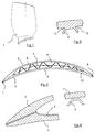
- a hollow turbine engine blade 1 in particular a blade of large rope blower intended for example for a schematic turbofan engine in Figures 1 and 2.
- the blade 1 consists of a skin lower surface 2, upper skin 3, these skins being spread apart to form an internal cavity 4 in which the disposed an element 5 forming multiple stiffeners 6 which ensure the connection between skins 2 and 3.
- said skins 2 and 3 are welded on their edges to form an edge leading edge 7 and a trailing edge 8 and the cavity 4 of the blade 1 has a radius 9 on the leading edge side and a radius 10 on the side of the trailing edge 8.
- the element 5 comprises welded areas, some on the underside skin 2 and others on the skin of upper surface 3 and thus the connections between the stiffeners 6 and the skins 2 and 3 form spokes such as 11 and 12, as shown diagrammatically in FIG. 3.
- the first step (a) of the process, according to the invention, of manufacture of a hollow blade such as 1 of a fan turbomachine comprises, from the drawing of the finished part a study using known means of Computer Aided Design and Manufacturing or CAD / CAM.
- This study simulates deflation of the skin extrados 3 and construction of element 5 or sheet metal central so as to rest these two elements on the lower sheet or place them at a known distance.
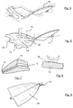
- FIG. 5 shows the blanks 13 which are at the origin of these constituent elements 2, 3 and 5 of dawn with their machining allowance and which are obtained by forcing and stamping on press.
- step (c) the blanks 13 are machined, as shown in Figure 6.
- Surface finish internal primary parts is produced by any process machining known per se.
- an extra thickness of material can be fitted on the skins primary all around the area of these skins intended to form the blade cavity.
- This part 14 in extra thickness then constitutes a creep zone intended for later be plastically deformed.
- a part 15 in excess thickness around the periphery of part is intended to ensure during assembly a spacing between the sheets.
- Figure 7 shows a detail of these extra thicknesses 14 and 15.
- the cutting can thus be carried out using a wheel such as 21 having asymmetrical sides 22 and 23, on a machine with digital control.
- the determined shape of the wheel 21 and a judicious adjustment of the tool pressure ensure high precision cutting.
- This cutting operation can also be carried out by means of a scalpel controlled by an electro-pneumatic system so as to ensure a clean cut without creating damage to the primary part 13.
- low-power laser machining can be used for a clean cut without creating damage to the primary part 13.
- Sub-step (d3) includes the peeling of zones 24 not welded, as shown in Figure 12.
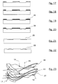
- the primary parts 13, 27, 28 constitutive of dawn as represented on the figure 23 are assembled using pins 17 and 18 and by placing lateral positioning pins 29 in the holes 19 previously formed on said parts primary.
- the assembly carried out allows to obtain a perfect alignment of the different parts and facing areas intended for the formation of the internal cavities of dawn and these provisions will make it possible in particular to obtain the adequate value of the cavity radius.
- Figure 24 shows schematically the completion of this assembly.
- the contour of the sandwich 30 obtained is closed, for example by means of a TIG arc, electron beam, or laser.
- At each end tubes are welded 30 and by means of these tubes 32, the vacuum is produced uniformly at inside the sandwich 30 then is held in place by sealing of these tubes 32.
- the presence of the extra thickness 15 in periphery of the intrados 28 and extrados 27 skins allows maintain a constant space between the component parts of dawn, during assembly.
- the sandwich 30 is welded by diffusion in an isostatic compression enclosure, so as to ensure intimate contact with the parts 13, 27 and 28 constituting dawn.
- FIGS. 25 and 26 show in one case the presence of positive flats 16 and lateral grooves 25 and in the other case of negative flats 33 and lateral grooves 25 on the primary parts in the areas intended for constitute the connections between stiffeners and skins as represented on the detail of part of figure 3.
- the presence grooves 25 protects this anti-diffusion product limit on the constituent parts of the blade by placing it at; below the level of the welding plane.
- the presence of a space constant at assembly between the constituent parts of dawn thanks to the extra thickness 15, as previously described, with reference to Figure 6, ensures during welding-diffusion an impurity trap function. Faults in possibly arising are then located in areas intended to be dropped.
- the constituent parts of the blade 1 are formed under superplastic conditions by applying an inflation pressure in the internal cavity 4 so as to obtain, as shown diagrammatically in FIG. 2, the profile sought on the aerodynamic surfaces of the blade blade on the pressure side 2 and suction side 3 and the installation of stiffeners 6 from the central primary part 13.
- the sandwich 30 is placed in a mold 34 schematically represented in Figure 27.
- the mold 34 is in two parts 35 and 36 and its characteristics ensure precise relative positioning of the two parts 35 and 36, according to the six degrees of freedom.
- the mold 34 comprises in particular anti-rotation stops 37 whose position as well as the determined mold closing means make it possible to block the parts 35 and 36 in horizontal rotation and in translation, from the start of the forming cycle.
- the centering Vs 38 of the lower part 35 in line with the pins 17 and 18, at the ends of the part, ensure the adequate position of the latter in the mold 34. Thanks to this rigorous positioning of the blade blank in the mold 34 avoids any offset of the blade, in particular a lateral displacement which would have the effect of crushing the cavity radii 9 and 10. These positioning characteristics of the mold and of the blade thus contribute to obtaining the dimensions and shapes of the starting dawn cavity radii sought for the finished dawn.
- a sub-step (f1) is carried out before inflation starts, comprising detachment of the primary cold parts which is required by the state of compaction of the anti-diffusion product.
- a predetermined forming pressurization cycle is then applied comprising in particular mechanical pressurization from the start of inflation, so as to ensure that there are no defects on the part obtained.
- a control is notably established between the clamping pressure of the mold and the inflation pressure.
- a sub-step (f2) occurs after the closure of the mold 34 during which a creep of the extra thickness 14 located around the area of formation of the blade cavity and previously mentioned is carried out.
- a controlled sequence of successive phases, creep then inflation simultaneously allows to generate the internal geometry of the blade and to avoid skin defects at the start of cavities.
- the cycle defined for the application of the internal gas pressure may in particular respect a controlled deformation speed, so as to ensure the obtaining of cavity spokes, spokes in the connection zones between skins and stiffeners, the required radius surface condition as well as the absence of stiffening of the stiffener.
- FIG. 28 thus shows a detail of necking defect 39 on a stiffener which is avoided by the method according to the invention. Controlling the rate of deformation obtained thanks to the positioning characteristics of the mold and the application of the forming cycle ensures the desired value of the radii 9,10,11 and 12.
- the blade 1 is extracted from the mold 34 by mechanical means, including a constraint which maintains the geometry of the part during this operation which is carried out while maintaining the temperature forming.
Landscapes
- Engineering & Computer Science (AREA)
- Mechanical Engineering (AREA)
- Physics & Mathematics (AREA)
- Fluid Mechanics (AREA)
- Turbine Rotor Nozzle Sealing (AREA)
- Structures Of Non-Positive Displacement Pumps (AREA)
- Pressure Welding/Diffusion-Bonding (AREA)
- Forging (AREA)
Description
La présente invention concerne un procédé de fabrication d'une aube creuse de turbomachine.The present invention relates to a manufacturing process of a hollow turbine engine blade.
Les avantages découlant de l'utilisation d'aubes à grande corde pour les turbomachines sont apparus notamment dans le cas des aubes de rotor de soufflante des turboréacteurs à double flux. Ces aubes doivent répondre à des conditions sévères d'utilisation et posséder notamment des caractéristiques mécaniques suffisantes associées à des propriétés d'endurance aux vibrations et de résistance aux impacts de corps étrangers. L'objectif de vitesses suffisantes en bout d'aube a en outre amené à rechercher une réduction des masses. Ce but est notamment atteint par l'utilisation d'aubes creuses.The benefits of using large blades rope for turbomachinery appeared especially in the case of the fan rotor blades of turbojet engines double flow. These blades must meet conditions severe use and in particular have sufficient mechanical characteristics associated with vibration endurance and resistance to impacts of foreign bodies. The speed target sufficient at the end of the dawn also led to the search for a mass reduction. This goal is notably achieved by the use of hollow blades.
L'aube de soufflante a une géométrie spécifique liée à la faible dimension de moyeu qui conduit à avoir une aube très cambrée en pied et un profil très plat en sommet de pale pour un taux de compression sensiblement constant sur la hauteur. De plus, il faut élaborer une forme géométrique adéquate de transition entre l'attache de l'aube et la pale aérodynamique proprement dite. Cela conduit à une géométrie fortement tridimensionnelle sur l'arrière du profil en partie basse appelée "cuillère" avec un cambrage dans le sens du profil et une cambrure dans le sens radial.The fan blade has a specific geometry related to the small hub dimension which leads to a very vane arched at the bottom and a very flat profile at the top of the blade for a substantially constant compression ratio over the height. In addition, an adequate geometric form of transition between the blade attachment and the aerodynamic blade proper. This leads to a strongly geometry three-dimensional on the back of the profile at the bottom called "spoon" with a camber in the direction of the profile and a camber in the radial direction.
Pour avoir une bonne tenue mécanique des aubes de soufflante creuses en alliage de titane, un soin particulier doit être apporté sur la conception de la géométrie interne et sa qualité de réalisation se traduisant par les spécifications suivantes :
- formation de rayon de raccordement au bord d'attaque et bord de fuite entre les deux peaux primaires intrados et extrados ;
- formation de rayon de raccordement entre le raidisseur et les peaux primaires intrados et extrados ;
- striction très faible dans les raidisseurs ;
- conservation des qualités mécaniques du métal de base lors de la réalisation de soudure diffusion, d'excellente qualité dans toutes les jonctions peaux/raidisseur ;
- obtention d'un état de surface des cavités internes après gonflage conforme aux exigences usuelles des pièces en titane ;
- optimisation de la gamme de fabrication afin de ne pas dégrader les caractéristiques mécaniques intrinsèques des aubes de soufflante en titane forgé.
- formation of a connection radius at the leading edge and trailing edge between the two intrados and extrados primary skins;
- formation of a connection radius between the stiffener and the intrados and extrados primary skins;
- very weak necking in stiffeners;
- conservation of the mechanical qualities of the base metal when performing diffusion welding, excellent quality in all skin / stiffener junctions;
- obtaining a surface condition of the internal cavities after inflation in accordance with the usual requirements for titanium parts;
- optimization of the production range so as not to degrade the intrinsic mechanical characteristics of the forged titanium fan blades.
En outre le procédé de fabrication doit permettre la
fabrication de pièces ayant des paramètres géométriques
évolutifs (variation d'épaisseur de peaux primaires du
raidisseur, variation de l'angle de formage du raidisseur,
variation de la largeur des zones soudées...).
La pièce fabriquée doit en effet être conforme aux exigences
d'une géométrie optimisée ayant une bonne tenue à la fatigue
vibratoire, une bonne tenue à l'ingestion et remplir toutes
les conditions de conception pour la durée de vie recherchée
sur moteur.In addition, the manufacturing process must allow the production of parts with evolving geometric parameters (variation in thickness of primary skins of the stiffener, variation in the forming angle of the stiffener, variation in the width of the welded zones, etc.).
The manufactured part must indeed comply with the requirements of an optimized geometry having good resistance to vibration fatigue, good resistance to ingestion and fulfilling all the design conditions for the desired service life on the engine.
On connaít notamment un procédé de fabrication d'une aube
creuse de turbomachine comportant les étapes suivantes
(voir, par exemple EP-A-0 500 458) :
Le but de l'invention est d'apporter aux nombreux procédés connus de fabrication d'aubes creuses des amélioration ou des spécificités substantielles visant notamment à obtenir des aubes présentant des caractéristiques mécaniques dans les conditions d'utilisation, gràce à une géométrie adéquate, en particulier en ce qui concerne la réalisation de la cavité de l'aube.The object of the invention is to provide the numerous methods known for making hollow blades improvements or substantial specificities aimed in particular at obtaining blades exhibiting mechanical characteristics in the conditions of use, thanks to an adequate geometry, in particularly with regard to the realization of the cavity of dawn.
Ces buts sont atteints par un procédé de fabrication d'une aube creuse de turbomachine, du type précité, caractérisé en ce que
- à l'étape (c), une réserve de matière dans des zones localisées de la face interne des peaux est aménagée et aux étapes (b) et (c), des éléments formant tourillon sont disposés à chaque extrémité des pièces primaires et au moins deux trous de locating sont aménagés sur chaque pièce,
- l'étape (d) est effectuée suivant le déroulé suivant :
- (d1) application d'un masque de type organique sur au moins une face d'au moins l'une des pièces primaires ;
- (d2) découpe du masque suivant un motif prédéfini représentant les limites des zones soudées et non soudées au moyen d'un outil spécifique sur machine à commande numérique, au cours de laquelle dans les zones correspondant aux raccordements du côté des bords d'attaque et de fuite de l'aube où se forme un rayon de cavité ainsi que dans les zones du rayon de raccordement entre les raidisseurs et les peaux, un réglage de la position de découpe du masque permet un décalage de la limite de soudure ;
- (d3) pelage des zones non soudées ;
- (d4) nettoyage des surfaces ;
- (d5) dépôt d'un produit de revêtement formant une barrière de diffusion sur les surfaces précédemment préparées ;
- (d6) pelage du masque restant ;
- (d7) traitement de précuisson du produit d'anti-diffusion ;
- (d8) nettoyage et contrôle des surfaces à souder ;
- à l'étape (e), l'étape d'assemblage des pièces primaires est effectuée en utilisant lesdits tourillons d'extrémités et des pions de positionnement latéraux placés dans lesdits trous de locating ;
- à l'étape (f), un cycle prédéterminé de mise en pression de
formage est appliqué comportant,
- (f1) avant démarrage du gonflage, un décollement des pièces primaires à froid est effectué ;
- (f2) après la fermeture du moule dans lequel est placée la pièce sous forme de sandwich obtenue à l'issue de l'étape (e), un fluage de la matière prévue en surépaisseur autour de la cavité de l'aube est effectué avant le gonflage ;
- (f3) après formage, l'aube est extraite du moule à la température de formage grâce à un moyen mécanique assurant une mise sous contrainte de l'aube.
- in step (c), a reserve of material in localized areas of the inner face of the skins is arranged and in steps (b) and (c), trunnion elements are arranged at each end of the primary parts and at least two locating holes are fitted on each piece,
- step (d) is carried out according to the following sequence:
- (d1) application of an organic type mask on at least one face of at least one of the primary parts;
- (d2) cutting of the mask according to a predefined pattern representing the limits of the welded and non-welded zones by means of a specific tool on a numerically controlled machine, during which in the zones corresponding to the connections on the side of the leading edges and of flight from the blade where a cavity radius is formed as well as in the zones of the connection radius between the stiffeners and the skins, an adjustment of the mask cutting position allows a shift of the weld limit;
- (d3) peeling of the non-welded areas;
- (d4) cleaning of surfaces;
- (d5) depositing a coating product forming a diffusion barrier on the previously prepared surfaces;
- (d6) peeling of the remaining mask;
- (d7) pre-baking treatment of the anti-diffusion product;
- (d8) cleaning and control of the surfaces to be welded;
- in step (e), the step of assembling the primary parts is carried out using said end trunnions and lateral positioning pins placed in said locating holes;
- in step (f), a predetermined forming pressurization cycle is applied comprising,
- (f1) before inflation starts, a separation of the cold primary parts is carried out;
- (f2) after closing the mold in which the part is placed in the form of a sandwich obtained at the end of step (e), a flow of the material provided in excess thickness around the cavity of the blade is carried out before inflation;
- (f3) after forming, the blade is extracted from the mold at the forming temperature by mechanical means ensuring that the blade is stressed.
Les dispositions de la présente invention permettent d'obtenir la géométrie interne assurant les propriétés recherchées de l'aube et notamment :
- une géométrie générale de la section principalement le nombre, la forme et la position des raidisseurs ainsi que la position et la largeur de la cavité ;
- une géométrie locale principalement aux limites de soudure départ cavité et liaison peau/raidisseurs. Par convention, nous ne différencierons pas le rayon de cavité du bord d'attaque et celui du bord de fuite qui sera dénommé rayon de cavité. De la même façon nous ne dissocierons pas les rayons de liaison peau/raidisseur quelle que soit leur position et nous les appellerons rayon de départ peau/raidisseur.
- a general geometry of the section mainly the number, the shape and the position of the stiffeners as well as the position and the width of the cavity;
- a local geometry mainly at the weld limits starting from the cavity and skin / stiffener connection. By convention, we will not differentiate the radius of cavity from the leading edge and that of the trailing edge which will be called radius of cavity. In the same way, we will not dissociate the skin / stiffener connecting spokes whatever their position and we will call them the starting skin / stiffener radius.
D'autres caractéristiques et avantages de l'invention seront mieux compris à la lecture de la description qui va suivre des modes de réalisation de l'invention, en référence aux dessins annexés sur lesquels :
- la figure 1 représente une vue de face d'une aube creuse de turbomachine obtenue par le procédé de fabrication conforme à l'invention ;
- la figure 2 représente une vue schématique en coupe par un plan transversal de l'aube représentée sur la figure 1 ;
- la figure 3 montre un détail de liaison entre deux éléments
de l'aube représentée sur les figures 1
et 2 ; - la figure 4 représente une vue partielle montrant les
détails de l'aube représentée sur les figures 1
et 2 ; - la figure 5 représente une vue schématique en perspective des pièces brutes utilisées dans le procédé de fabrication conforme à l'invention ;
- la figure 6 représente une vue schématique en perspective
d'un élément constitutif de l'aube représentée sur les
figures 1
et 2 au stade de l'usinage ; - les figures 7
et 8 représentent des vues partielles en coupe des éléments de l'aube représentée sur les figures 1et 2 montrant des surépaisseurs aménagées au stade de l'usinage; - la figure 9 représente une vue en perspective d'un élément
de l'aube représentée sur les figures 1
et 2 montrant la mise en place d'un masque ; - la figure 10 représente selon une vue schématique en coupe l'élément représenté sur la figure 9 ;
- la figure 11 représente selon une vue schématique en coupe similaire à celle de la figure 10 l'élément représenté sur les figures 9 et 10 au stade de la découpe du masque ;
- la figure 12 représente selon une vue schématique en coupe similaire à celle des figures 10 et 11 l'élément représenté sur les figures 9 à 11 au stade du pelage du masque ;
- la figure 13 représente selon une vue schématique en coupe similaire à celles des figures 10 à 12 l'élément représenté sur les figures 9 à 12 selon une variante du stade de la découpe du masque ;
- la figure 14 représente selon une vue schématique en coupe similaire à celle des figures 10 à 13 l'élément de la figure 13 au stade du pelage du masque ;
- la figure 15 représente selon une vue schématique en coupe similaire à celle des figures 10 à 14 l'élément des figures 13 et 14 au stade de l'usinage chimique de rainures ;
- la figure 16 représente selon une vue schématique en coupe similaire à celle des figures 10 à 15 l'élément des figures 13 à 15 au stade du pelage du masque restant ;
- la figure 17 représente selon une vue schématique en coupe similaire à celle des figures 10 à 16 l'élément représenté sur la figure 9 à la suite d'un usinage chimique effectué en variante ;
- la figure 18 représente selon une vue schématique en coupe similaire à celle des figures 10 à 17 l'élément de la figure 17 à la suite de la réalisation de zones rainurées ;
- les figures 19 et 20 représentent selon des vues schématiques en coupe similaire à celles des figures 10 à 18 respectivement l'élément de la figure 17 et l'élément de la figure 18 au stade du dépôt d'une barrière de diffusion ;
- les figures 21 et 22 représentent selon des vues schématiques en coupe similaires à celles des figures 10 à 20 respectivement l'élément des figures 17 et 19 et l'élément des figures 18 et 20 au stade de pelage du masque restant ;
- la figure 23 représente selon une vue en perspective l'assemblage des pièces primaires constitutives de l'aube ;
- la figure 24 représente selon une vue en perspective l'achèvement de l'assemblage schématisé sur la figure 23 ;
- les figures 25 et 26 montrent selon des vues partielles schématiques en coupe deux détails de réalisation de méplats dans la liaison entre éléments de l'aube ;
- la figure 27 représente selon une vue schématique en perspective les deux parties constitutives du moule utilisé dans l'étape de formage superplastique de l'aube selon le procédé conforme à l'invention ;
- la figure 28 représente selon une vue similaire à celle de la figure 7 un détail montrant un défaut de fabrication.
- FIG. 1 represents a front view of a hollow blade of a turbomachine obtained by the manufacturing method according to the invention;
- 2 shows a schematic sectional view through a transverse plane of the blade shown in Figure 1;
- Figure 3 shows a connection detail between two elements of the blade shown in Figures 1 and 2;
- Figure 4 shows a partial view showing the details of the blade shown in Figures 1 and 2;
- Figure 5 shows a schematic perspective view of the raw parts used in the manufacturing process according to the invention;
- Figure 6 shows a schematic perspective view of a component of the blade shown in Figures 1 and 2 at the machining stage;
- Figures 7 and 8 show partial sectional views of the elements of the blade shown in Figures 1 and 2 showing extra thicknesses arranged at the machining stage;
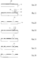
- Figure 9 shows a perspective view of an element of the blade shown in Figures 1 and 2 showing the placement of a mask;
- Figure 10 shows in a schematic sectional view the element shown in Figure 9;
- Figure 11 shows in a schematic sectional view similar to that of Figure 10 the element shown in Figures 9 and 10 at the stage of cutting the mask;
- Figure 12 shows in a schematic sectional view similar to that of Figures 10 and 11 the element shown in Figures 9 to 11 at the peeling stage of the mask;
- Figure 13 shows in a schematic sectional view similar to those of Figures 10 to 12 the element shown in Figures 9 to 12 according to a variant of the stage of cutting the mask;
- Figure 14 shows in a schematic sectional view similar to that of Figures 10 to 13 the element of Figure 13 at the stage of peeling of the mask;
- Figure 15 shows in a schematic sectional view similar to that of Figures 10 to 14 the element of Figures 13 and 14 at the stage of chemical machining of grooves;
- Figure 16 shows in a schematic sectional view similar to that of Figures 10 to 15 the element of Figures 13 to 15 at the peeling stage of the remaining mask;
- Figure 17 shows in a schematic sectional view similar to that of Figures 10 to 16 the element shown in Figure 9 following a chemical machining performed as an alternative;
- Figure 18 shows in a schematic sectional view similar to that of Figures 10 to 17 the element of Figure 17 following the production of grooved areas;
- Figures 19 and 20 show in schematic sectional views similar to those of Figures 10 to 18 respectively the element of Figure 17 and the element of Figure 18 at the stage of depositing a diffusion barrier;
- Figures 21 and 22 show in schematic sectional views similar to those of Figures 10 to 20 respectively the element of Figures 17 and 19 and the element of Figures 18 and 20 in the peeling stage of the remaining mask;
- Figure 23 shows in a perspective view the assembly of the primary parts constituting the blade;
- Figure 24 shows in a perspective view the completion of the assembly shown schematically in Figure 23;
- Figures 25 and 26 show in partial schematic sectional views two details of realization of flats in the connection between elements of the blade;
- Figure 27 shows in a schematic perspective view the two constituent parts of the mold used in the superplastic forming step of the blade according to the method according to the invention;
- Figure 28 shows in a view similar to that of Figure 7 a detail showing a manufacturing defect.
Une aube 1 creuse de turbomachine, notamment une aube de
soufflante à grande corde destinée par exemple à un
turboréacteur à double flux est schématiquement représentée
sur les figures 1 et 2. L'aube 1 est constituée d'une peau
d'intrados 2, d'une peau d'extrados 3, ces peaux étant
écartées pour former une cavité interne 4 dans laqueile est
disposé un élément 5 formant de multiples raidisseurs 6 qui
assurent la liaison entre les peaux 2 et 3. Dans l'aube 1
obtenue selon le procédé de fabrication dont les
améliorations font l'objet de l'invention, lesdites peaux 2
et 3 sont soudées sur leurs bords pour former un bord
d'attaque 7 et un bord de fuite 8 et la cavité 4 de l'aube 1
présente un rayon 9 du côté du bord d'attaque et un rayon 10
du côté du bord de fuite 8. De même, l'élément 5 comporte des
zones soudées, les unes sur la peau d'intrados 2 et les
autres sur la peau d'extrados 3 et ainsi les liaisons entre
les raidisseurs 6 et les peaux 2 et 3 forment des rayons tels
que 11 et 12, comme schématisé sur la figure 3.A hollow
Le première étape (a) du procédé, conforme à l'invention, de
fabrication d'une aube creuse telle que 1 de soufflante de
turbomachine comporte, à partir du dessin de la pièce finie
une étude faisant appel à des moyens connus en soi de
Conception et Fabrication Assistés par Ordinateur ou CFAO.
Cette étude permet de simuler un dégonflage de la peau
d'extrados 3 et la construction de l'élément 5 ou tôle
centrale de manière à faire reposer ces deux éléments sur la
tôle intrados ou à les placer à une distance connue. Le
logiciel de simulation utilisé permet de préciser le
mouvement relatif des tôles lors du formage. Pour obtenir la
géométrie ainsi définie, chaque élément constitutif de
l'aube, respectivement 2, 3 et 5, appelé pièce primaire
reçoit des surépaisseurs compatibles avec le processus de
forgeage prévu, comme schématisé sur la figure 4.The first step (a) of the process, according to the invention, of
manufacture of a hollow blade such as 1 of a fan
turbomachine comprises, from the drawing of the finished part
a study using known means of
Computer Aided Design and Manufacturing or CAD / CAM.
This study simulates deflation of the
La figure 5 montre les pièces brutes 13 à l'origine de ces
éléments constitutifs 2, 3 et 5 de l'aube avec leur
surépaisseur d'usinage et qui sont obtenues par forceage et
matricage sur presse. Ce processus amélioré permet d'obtenir
une géométrie et un produit d'une grande précision avec des
caractéristiques mécaniques améliorées, suivant l'étape (b)
du procédé.FIG. 5 shows the
A l'étape (c), les pièces brutes 13 sont usinées, comme
représentées sur la figure 6. La finition de la surface
interne des pièces primaires est réalisée par tout procédé
d'usinage connu en soi. A ce stade et de manière avantageuse,
une surépaisseur de matière peut être aménagée sur les peaux
primaires sur tout le pourtour de la zone de ces peaux
destinée à former la cavité d'aube. Cette partie 14 en
surépaisseur constitue alors une zone de fluage destinée à
être ultérieurement déformée plastiquement. De la même
manière, une partie 15 en surépaisseur sur le pourtour de
pièce est destinée à assurer lors de l'assemblage un
espacement entre les tôles. La figure 7 montre un détail de
ces surépaisseurs 14 et 15.In step (c), the
De manière avantageuse, des surépaisseurs localisées de type méplats 16 peuvent également être aménagées à l'étape (c) sur la face interne des peaux primaires dans les zones d'emplacement des soudures de liaison entre peau et raidisseur, comme schématisé sur la figure 8. Les peaux primaires telles que 13 comportent à chaque extrémité des tourillons 17 et 18 qui seront utilisés lors des étapes suivantes du procédé. En outre, au moins deux trous 19 de locating sont usinés sur les pièces primaires. De manière avantageuse, l'opération d'usinage peut être effectuée sur des outillages à dépression de manière à assurer la précision recherchée du positionnement des zones de cavité l'une par rapport à l'autre. Ces précautions sont essentielles pour obtenir les rayons de cavité adéquats. A l'étape d, un dépôt de barrières de diffusion est effectué suivant un motif prédéfini. De façon plus détaillée, cette opération est décomposée de la manière suivante :
- (d1)
application d'un masque 20 de type organique sur au moins une face d'au moins une des pièces primaires 13, telle que représentée sur les figures 9 et 10, - (d2) découpe du masque 20 suivant un motif prédéfini représentant les limites des zones soudées et non soudées, comme le schématise la figure 11. L'utilisation d'un outil spécifique sur machine à commande numérique permet un réglage précis de la position de découpe du masque.
- (d1) application of an
organic type mask 20 on at least one face of at least one of theprimary parts 13, as shown in FIGS. 9 and 10, - (d2) cutting of the
mask 20 according to a predefined pattern representing the limits of the welded and non-welded areas, as shown in FIG. 11. The use of a specific tool on a numerically controlled machine allows precise adjustment of the cutting position of the mask.
La découpe peut ainsi être réalisée à l'aide d'une molette
telle que 21 présentant des flancs dissymétriques 22 et 23,
sur une machine à commande numérique. La forme déterminée de
la molette 21 et un réglage judicieux de la pression d'outil
assurent une découpe de haute précision.
Cette opération de découpe peut également être réalisée au
moyen d'un scalpel asservi par un système électro-pneumatique
de manière à assurer une découpe nette sans créer de dommage
sur la pièce primaire 13.
En fonction des applications particulières, un usinage au
laser à faible puissance peut être utilisé pour une découpe
nette sans créer de dommage sur la pièce primaire 13.The cutting can thus be carried out using a wheel such as 21 having
This cutting operation can also be carried out by means of a scalpel controlled by an electro-pneumatic system so as to ensure a clean cut without creating damage to the
Depending on the particular application, low-power laser machining can be used for a clean cut without creating damage to the
La sous-étape (d3) comporte le pelage des zones 24 non
soudées, comme schématisé sur la figure 12.Sub-step (d3) includes the peeling of
Une première variante prévoit des sous-étapes complémentaires:
- (d2') découpe du masque 20, en créant des zones rainurées 25 suivant un motif prédéfini représentant des parallèles aux zones soudées, comme le schématise la figure 13,
- (d3') pelage des
zones 25 à rainurer en bordure des zones à souder entre peaux et raidisseurs, comme schématisé sur la figure 14, - (d3'') usinage chimique de rainures dans lesdites zones
découvertes en (d3'), comme schématisé sur la figure 15,
- (d3''') pelage du masque restant afin de découvrir les
zones 24 comme le schématise la figure 16.
- (d2 ′) cutting of the
mask 20, by creatinggrooved areas 25 in a predefined pattern representing parallels to the welded areas, as shown in FIG. 13, - (d3 ′) peeling of the
zones 25 to be grooved at the edge of the zones to be welded between skins and stiffeners, as shown diagrammatically in FIG. 14, - (d3 '') chemical machining of grooves in said areas discovered in (d3 '), as shown diagrammatically in FIG. 15, - (d3''') peeling of the remaining mask in order to discover the
areas 24 as shown schematically in Figure 16.
Une autre variante prévoit un usinage chimique, par exemple
d'une profondeur maximale de 0,75 mm, afin de créer une
limite franche en bordure de découpe, comme schématisé sur la
figure 17 montrant les zones 24 ou sur la figure 18 avec les
zones rainurées 25.
Le procédé se poursuit par les sous-étapes suivantes :
- (d4) nettoyage des surfaces
- (d5) dépôt d'un produit de revêtement 26 formant une barrière de diffusion sur les surfaces précédemment préparées, comme indiqué sur les figures 19 et 20 avec ou sans rainures. Ledit produit est déposé par pulvérisation en couches successives d'une épaisseur pouvant atteindre 40 µm. Après chaque application, on réalise un séchage.
- (d6) pelage du masque restant, la pièce étant maintenue
dans une position évitant toute retombée de produit
antidiffusion sur les zones à souder. Le résultat obtenu
est schématisé sur les figures 21
et 22, avec ou sans rainures. - (d7) traitement de précuisson du produit d'anti-diffusion. La température est choisie entre 250°C et 350°C durant un temps prédéterminé pour assurer un taux de dégradation de la majeure partie du liant contenu dans le produit antidiffusion compatible avec la suite des opérations et de manière à éviter toute oxydation des pièces, cette dégradation s'effectuant en l'absence d'air ;
- (d8) les zones à souder sont nettoyées, leur propreté est soigneusement contrôlée, par exemple sous lumière ultraviolette.
The process continues with the following sub-steps:
- (d4) cleaning of surfaces
- (d5) depositing a
coating product 26 forming a diffusion barrier on the previously prepared surfaces, as indicated in FIGS. 19 and 20 with or without grooves. Said product is deposited by spraying in successive layers with a thickness of up to 40 μm. After each application, drying is carried out. - (d6) peeling of the remaining mask, the part being held in a position preventing any fall of anti-diffusion product on the areas to be welded. The result obtained is shown diagrammatically in FIGS. 21 and 22, with or without grooves.
- (d7) pre-baking treatment of the anti-diffusion product. The temperature is chosen between 250 ° C and 350 ° C for a predetermined time to ensure a degradation rate of most of the binder contained in the anti-diffusion product compatible with the rest of the operations and so as to avoid any oxidation of the parts, this degradation occurring in the absence of air;
- (d8) the areas to be welded are cleaned, their cleanliness is carefully checked, for example under ultraviolet light.
A l'étape suivante (e), les pièces primaires 13, 27, 28
constitutives de l'aube, telles que représentées sur la
figure 23 sont assemblées en utilisant les tourillons 17 et
18 et en plaçant des pions 29 de positionnement latéraux dans
les trous 19 précédemment ménagés sur lesdites pièces
primaires. L'assemblage effectué permet d'obtenir un parfait
alignement des différentes pièces et des zones en vis à vis
destinées à la formation des cavités internes de l'aube et
ces dispositions permettront notamment l'obtention de la
valeur adéquate du rayon de cavité.In the next step (e), the
La figure 24 schématise l'achèvement de cet assemblage. Le
contour du sandwich 30 obtenu est fermé, par exemple au moyen
d'une soudure 31 à l'arc TIG, par faisceau d'électrons ou au
laser. A chaque extrémité on soude des tubes 30 et au moyen
de ces tubes 32, le vide est réalisé uniformément à
l'intérieur du sandwich 30 puis est maintenu par scellement
de ces tubes 32. La présence de la surépaisseur 15 en
périphérie des peaux intrados 28 et extrados 27 permet de
ménager un espace constant entre les pièces constitutives de
l'aube, lors de l'assemblage.Figure 24 shows schematically the completion of this assembly. The
contour of the
En variante, à la suite de l'assemblage du sandwich 30, il
est possible de réaliser la cuisson du produit de diffusion
mis en place à l'étape précédente (d).As a variant, following the assembly of the
Après assemblage, le sandwich 30 est soudé par diffusion dans
une enceinte de compression isostatique, de manière à assurer
un contact intime des pièces 13, 27 et 28 constitutives de
l'aube.After assembly, the
Au cours de cette opération, les mouvements induits lors de
la mise sous pression accompagnant la mise en contact des
surfaces internes peuvent entraíner par frottement le
déplacement et/ou la détérioration de la limite du produit
anti diffusion. Les détails de réalisation représentés sur
les figures 25 et 26 montrent dans un cas la présence de
méplats positifs 16 et de rainures latérales 25 et dans
l'autre cas de méplats négatifs 33 et de rainures latérales
25 sur les pièces primaires dans les zones destinées à
constituer les liaisons entre raidisseurs et peaux comme
représenté sur le détail de pièce de la figure 3. La présence
des rainures 25 protège cette limite de produit antidiffusion
sur les pièces constitutives de l'aube en la plaçant au;
dessous du niveau du plan de soudure. La présence d'un espace
constant à l'assemblage entre les pièces constitutives de
l'aube grâce à la surépaisseur 15, comme précédemment décrit,
en référence à la figure 6, assure lors de la soudure-diffusion
une fonction de piège à impureté. Les défauts en
découlant éventuellement sont alors localisés dans des zones
destinées à être chutées.During this operation, the movements induced during
pressurization accompanying the contacting of
internal surfaces can cause friction
displacement and / or deterioration of the product boundary
anti diffusion. The details of realization represented on
Figures 25 and 26 show in one case the presence of
A l'étape suivante (f), est effectué un formage des pièces
constitutives de l'aube 1 dans des conditions superplastiques
en appliquant dans la cavité interne 4 une pression de
gonflage de manière à obtenir, comme schématisé sur la figure
2, le profil recherché sur les surfaces aérodynamiques de
pale d'aube côté intrados 2 et côté extrados 3 et la mise en
place des raidisseurs 6 issus de la pièce primaire centrale
13. Dans ce but, le sandwich 30 est mis en place dans un
moule 34 schématiquement représenté sur la figure 27. Le
moule 34 est en deux parties 35 et 36 et ses caractéristiques
permettent d'assurer un positionnement relatif précis des
deux parties 35 et 36, suivant les six degrés de liberté. Le
moule 34 comporte notamment des butées anti-rotation 37 dont
la position ainsi que les moyens de fermeture du moule
déterminés permettent d'assurer un blocage des parties 35 et
36 en rotation horizontale et en translation, dès le début du
cycle de formage. Les V de centrage 38 de la partie
inférieure 35, au droit des tourillons 17 et 18, aux
extrémités de pièce, assurent la position adéquate de celle-ci
dans le moule 34. Grâce à ce positionnement rigoureux de
l'ébauche d'aube dans le moule 34 on évite tout déport de
l'aube, notamment un déplacement latéral qui aurait pour
effet de venir écraser les rayons de cavité 9 et 10. Ces
caractéristiques de positionnement du moule et de l'aube
concourent ainsi à l'obtention des dimensions et formes des
rayons de départ de cavité d'aube recherchés pour l'aube
finie.
Avant l'opération de formage proprement dite, une sous-étape
(f1) est effectuée avant démarrage du gonflage, comportant un
décollement des pièces primaires à froid qui est nécessité
par l'état de compactage du produit antidiffusion. Un cycle
prédéterminé de mise en pression de formage est ensuite
appliqué comportant notamment la mise en pression mécanique
dès le démarrage du gonflage, de manière à assurer une
absence de défauts sur la pièce obtenue. Un asservissement
est notamment établi entre la pression de serrage du moule et
la pression de gonflage. Une sous-étape (f2) intervient après
la fermeture du moule 34 au cours de laquelle on réalise un
fluage de la surépaisseur 14 localisée autour de la zone de
formation de la cavité d'aube et précédemment mentionnée. Un
enchaínement piloté des phases successives, fluage puis
gonflage permet simultanément de générer la géométrie interne
de l'aube et d'éviter des défauts de peau au droit des
départs de cavité. Durant le formage, le cycle défini pour
l'application de la pression gazeuse interne peut notamment
respecter une vitesse de déformation contrôlée, de manière à
assurer l'obtention des rayons de cavité, des rayons dans les
zones de liaison entre peaux et raidisseurs, de l'état de
surface de rayon requis ainsi que de l'absence de striction
du raidisseur. La figure 28 montre ainsi un détail de défaut
de striction 39 sur un raidisseur qui est évité par le
procédé conforme à l'invention. La maítrise du taux de
déformation obtenue grâce aux caractéristiques de
positionnement du moule et à l'application du cycle de
formage permet d'assurer la valeur recherchée des rayons
9,10,11 et 12.
A la sous-étape suivante (f3), après formage, l'aube 1 est
extraite du moule 34 par un moyen mécanique, incluant une
mise sous contrainte qui maintient la géométrie de la pièce
lors de cette opération qui est réalisée en maintenant la
température de formage. In the next step (f), the constituent parts of the
Before the actual forming operation, a sub-step (f1) is carried out before inflation starts, comprising detachment of the primary cold parts which is required by the state of compaction of the anti-diffusion product. A predetermined forming pressurization cycle is then applied comprising in particular mechanical pressurization from the start of inflation, so as to ensure that there are no defects on the part obtained. A control is notably established between the clamping pressure of the mold and the inflation pressure. A sub-step (f2) occurs after the closure of the
In the following sub-step (f3), after forming, the
L'étape suivante (g) comporte enfin l'usinage final et les opérations de finition de la pièce, de manière connue en soi. Les modalités particulières de réalisation du procédé conforme à l'invention de fabrication d'une aube 1 creuse de turbomachine qui viennent d'être décrites assurent l'obtention des résultats recherchés et notamment la qualité technique de l'aube 1. On rappellera brièvement ces principaux résultats précédemment détaillés :
- obtention de la valeur des rayons 9 et 10 de départ de
cavité recherchés et de la valeur du rayon de départ de
soudure dans la zone de liaison entre les peaux 2
et 3 et les raidisseurs 6, - positionnement adéquat de la ligne de soudure dans les zones mentionnées ci-dessus, au rayon de cavité et au rayon entre peaux et raidisseurs,
- qualité métallurgique du métal de base obtenue dans les zones mentionnées ci-dessus,
- état de surface adéquat dans le rayon 9
ou 10 de départ de cavité de l'aube, - rectitude et netteté des départs de soudure entre peaux et raidisseurs,
- rectitude et absence de striction des raidisseurs 6,
- qualité de la géométrie extérieure de l'aube 1, notamment concernant la forme du profil, le vrillage, le cambrage et le désaxage.
- obtaining the value of the starting
radii skins stiffeners 6, - adequate positioning of the weld line in the areas mentioned above, at the radius of the cavity and at the radius between the skins and stiffeners,
- metallurgical quality of the base metal obtained in the areas mentioned above,
- adequate surface finish in the starting
radius - straightness and sharpness of the weld starts between skins and stiffeners,
- straightness and lack of constriction of the
stiffeners 6, - quality of the external geometry of the
blade 1, in particular concerning the shape of the profile, the twist, the bending and the offset.
Claims (11)
- Method of manufacturing a hollow turbine machine blade, particularly a wide-chord fan rotor blade, including the following stages:(a) on the basis of the definition of a blade (1) to be obtained, study, using Computer Aided Design and Manufacture/CADCAM of the pieces (2, 3, 5) constituting the blade;(b) forging of the primary pieces (13) on a press;(c) machining of the primary pieces (13) comprising a pressure face skin, a suction face skin and at least one central piece;(d) deposition of diffusion barriers according to a predefined pattern;(e) assembly of the primary pieces followed by isostatic-pressure diffusion welding;(f) inflation under gas pressure and superplastic forming so as to shape the pressure face and suction face skins of the blade, which are separated by a central cavity and linked by welded stiffeners obtained from the said central piece;(g) final machining;
characterized in that,at stage (c), spare material is left in localized regions (14, 15) of the inner face of the skins, and, at stages (b) and (c), elements forming a trunnion (17, 18) are arranged at each end of the primary pieces and at least two locating holes (19) are formed on each piece,stage (d) is carried out according to the following process:(d1) application of an organic-type mask (20) onto at least one face of at least one of the primary pieces;(d2) cutting out the mask (20) according to a predefined pattern representing the limits of the welded and unwelded regions by means of a special-purpose tool on a numerically controlled machine, setting of the position for cutting out the mask allowing control of the position of the welds in the regions corresponding to the connections on the leading and trailing edge sides of the blade where a cavity radius is formed, as well as the regions of the radius of connection between the stiffeners and the skins;(d3) peeling of the unwelded regions;(d4) cleaning of the surfaces;(d5) deposition of a coating product forming a diffusion barrier on the previously prepared surfaces;(d6) peeling of the remaining mask;(d7) prefiring treatment of the anti-diffusion product;(d8) cleaning and checking of the surfaces to be welded;at stage (e), the stage of assembling the primary pieces is carried out using the said end trunnions (17, 18) and lateral positioning pins (29) placed in said locating holes (19);at stage (f), a predetermined cycle for applying forming pressure is applied, including,(f1) before starting the inflation, cold-debonding of the primary pieces is carried out;(f2) after closing the mould in which is placed the piece, in sandwich form, obtained on completion of stage (e), the material (14) provided as an overthickness around the cavity of the blade is made to flow before the inflation;(f3) after forming, the blade is extracted from the mould at the forming temperature by virtue of a mechanical means placing the blade under stress. - Method of manufacturing a hollow turbine machine blade according to Claim 1, in which, at stage (d2), the special-purpose tool used is a cutting disc (21) with asymmetric flanks (22, 23), so that the defined shape of the cutting disc and the setting of the tool pressure provide a high cutting precision.
- Method of manufacturing a hollow turbine machine blade according to Claim 1, in which, at stage (d2) the special-purpose tool is a scalpel servocontrolled by an electropneumatic system so as to provide a clean cut without causing damage to the primary piece.
- Method of manufacturing a hollow turbine machine blade according to Claim 1, in which, at stage (d2), cutting out of the mask is carried out by means of low-power laser machining providing a clean cut without causing damage to the primary piece.
- Method of manufacturing a hollow turbine machine blade according to any one of Claims 1 to 4, in which stage (d3) is broken down into substages:(d3')peeling of regions to be grooved (25);(d3'')chemical machining of grooves at the border of the regions to be welded;(d3''') second peeling of the unwelded regions.
- Method of manufacturing a hollow turbine machine blade according to any one of Claims 1 to 5, in which stage (d2) is preceded by the following substages:(d1.1) peeling of the regions to be welded;(d1.2) chemical machining of the uncovered regions;(d1.3) second application of a mask on the regions to be welded.
- Method of manufacturing a hollow turbine machine blade according to any one of Claims 1 to 6, in which, at stage (c) an overthickness (14) of material is formed over the entire periphery of that region of the primary skins intended to form the blade cavity, this part with overthickness constituting a flow region plastically deformed at stage (f).
- Method of manufacturing a hollow turbine machine blade according to any one of Claims 1 to 7, in which, at stage (c) localized overthicknesses in the form of flat surfaces (16) are formed on the inner face of the primary skins in the regions where the welds for linking between skin and stiffener are located.
- Method of manufacturing a hollow turbine machine blade according to any one of Claims 1 to 8, in which, at stage (e), after assembling the primary pieces forming a sandwich (30), the contour of the sandwich (30) is closed by forming a seal, and tubes (32) are welded to the end.
- Method of manufacturing a hollow turbine machine blade according to Claim 9, in which the closure (31) of the sandwich (30) is achieved by TIG or energy-beam welding.
- The method of manufacturing a hollow turbine machine blade according to any one of Claims 1 to 10, in which, following the assembling of the sandwich (30), firing of the product forming the diffusion barriers is carried out.
Applications Claiming Priority (2)
| Application Number | Priority Date | Filing Date | Title |
|---|---|---|---|
| FR9511300 | 1995-09-27 | ||
| FR9511300A FR2739045B1 (en) | 1995-09-27 | 1995-09-27 | PROCESS FOR MANUFACTURING A HOLLOW BLADE OF A TURBOMACHINE |
Publications (2)
| Publication Number | Publication Date |
|---|---|
| EP0765711A1 EP0765711A1 (en) | 1997-04-02 |
| EP0765711B1 true EP0765711B1 (en) | 2000-01-05 |
Family
ID=9482942
Family Applications (1)
| Application Number | Title | Priority Date | Filing Date |
|---|---|---|---|
| EP96402041A Expired - Lifetime EP0765711B1 (en) | 1995-09-27 | 1996-09-26 | Method of fabricating a hollow turbine blade |
Country Status (7)
| Country | Link |
|---|---|
| US (1) | US5826332A (en) |
| EP (1) | EP0765711B1 (en) |
| JP (1) | JP3281551B2 (en) |
| CA (1) | CA2186562C (en) |
| DE (1) | DE69605998T2 (en) |
| ES (1) | ES2140805T3 (en) |
| FR (1) | FR2739045B1 (en) |
Cited By (1)
| Publication number | Priority date | Publication date | Assignee | Title |
|---|---|---|---|---|
| CN104227103A (en) * | 2014-07-24 | 2014-12-24 | 西安航空学院 | Method for stepped symmetrical milling of thin-wall part |
Families Citing this family (44)
| Publication number | Priority date | Publication date | Assignee | Title |
|---|---|---|---|---|
| FR2752388B1 (en) * | 1996-08-14 | 1998-09-18 | Snecma | PROCESS FOR THE MANUFACTURE OF A HOLLOW BLADE OF A TURBOMACHINE COMPRISING A TAKE-OFF AFTER WELDING |
| FR2752539B1 (en) | 1996-08-22 | 1998-09-18 | Snecma | PROCESS FOR MANUFACTURING A HOLLOW BLADE OF A TURBOMACHINE AND HOT-SCALABLE TURNING EQUIPMENT |
| FR2754478B1 (en) * | 1996-10-16 | 1998-11-20 | Snecma | PROCESS FOR MANUFACTURING A HOLLOW BLADE OF A TURBOMACHINE |
| FR2820062B1 (en) * | 2001-02-01 | 2003-03-07 | Snecma Moteurs | INSTALLATION FOR FORMING A WORKPIECE AND APPLICATION TO HOT FORMING |
| DE10145241C2 (en) * | 2001-09-13 | 2003-07-17 | Benteler Automobiltechnik Gmbh | Process for the production of sheet metal products varying in thickness |
| GB0203955D0 (en) | 2002-02-20 | 2002-04-03 | Rolls Royce Plc | A method of manufacturing an article by diffusion bonding and super[lastic forming |
| US6705011B1 (en) | 2003-02-10 | 2004-03-16 | United Technologies Corporation | Turbine element manufacture |
| FR2852537B1 (en) * | 2003-03-21 | 2005-06-17 | Snecma Moteurs | ASSEMBLY FOR MANUFACTURING A HOLLOW-DIFFUSION HOLLOW MECHANICAL PIECE AND SUPERPLASTIC FORMING, USE OF SUCH AN ASSEMBLY AND METHOD OF MANUFACTURING SUCH A MECHANICAL PIECE |
| FR2853572B1 (en) * | 2003-04-10 | 2005-05-27 | Snecma Moteurs | METHOD FOR MANUFACTURING A HOLLOW MECHANICAL WELDING-DIFFUSION MECHANICAL PIECE AND SUPERPLASTIC FORMING |
| DE102004001666A1 (en) * | 2004-01-12 | 2005-08-04 | Mtu Aero Engines Gmbh | Method for producing hollow blades |
| FR2871397B1 (en) * | 2004-06-11 | 2006-09-22 | Snecma Moteurs Sa | INSTALLATION OF CONFORMATION OF A HOLLOW AUBE |
| FR2874339B1 (en) * | 2004-08-23 | 2008-12-05 | Snecma Moteurs Sa | METHOD FOR MANUFACTURING CONSTITUENT PIECES OF A HOLLOW DRAW BY DRILLING ON PRESS |
| GB0522121D0 (en) * | 2005-10-29 | 2005-12-07 | Rolls Royce Plc | A blade |
| GB0614186D0 (en) * | 2006-07-18 | 2006-08-23 | Rolls Royce Plc | Blades |
| GB2450935B (en) * | 2007-07-13 | 2009-06-03 | Rolls Royce Plc | Component with internal damping |
| GB2450934B (en) * | 2007-07-13 | 2009-10-07 | Rolls Royce Plc | A Component with a damping filler |
| GB0808840D0 (en) | 2008-05-15 | 2008-06-18 | Rolls Royce Plc | A compound structure |
| GB2462102B (en) * | 2008-07-24 | 2010-06-16 | Rolls Royce Plc | An aerofoil sub-assembly, an aerofoil and a method of making an aerofoil |
| RU2412017C2 (en) * | 2008-12-24 | 2011-02-20 | ОАО "Авиадвигатель" | Method of producing hollow fan vane |
| GB0901235D0 (en) * | 2009-01-27 | 2009-03-11 | Rolls Royce Plc | An article with a filler |
| GB0901318D0 (en) * | 2009-01-28 | 2009-03-11 | Rolls Royce Plc | A method of joining plates of material to form a structure |
| GB0903281D0 (en) * | 2009-02-27 | 2009-04-08 | Rolls Royce Plc | Method of manufacturing a blade |
| GB0903280D0 (en) * | 2009-02-27 | 2009-04-08 | Rolls Royce Plc | Method of manufacturing a blade |
| GB0903613D0 (en) * | 2009-03-04 | 2009-04-08 | Rolls Royce Plc | Method of manufacturing an aerofoil |
| GB0911416D0 (en) * | 2009-07-02 | 2009-08-12 | Rolls Royce Plc | A method of forming an internal structure within a hollow component |
| GB201009216D0 (en) | 2010-06-02 | 2010-07-21 | Rolls Royce Plc | Rotationally balancing a rotating part |
| GB2485831B (en) | 2010-11-26 | 2012-11-21 | Rolls Royce Plc | A method of manufacturing a component |
| JP5205499B2 (en) * | 2011-08-11 | 2013-06-05 | 橋田技研工業株式会社 | Manufacturing method of stationary blade for steam turbine |
| CN103089317B (en) * | 2011-10-31 | 2015-06-10 | 中航商用航空发动机有限责任公司 | Hollow fan blade and manufacturing method thereof |
| CN103089323B (en) * | 2011-10-31 | 2015-01-14 | 中航商用航空发动机有限责任公司 | Hollow fan blade and manufacturing method thereof |
| US11000899B2 (en) | 2012-01-29 | 2021-05-11 | Raytheon Technologies Corporation | Hollow airfoil construction utilizing functionally graded materials |
| FR2994887B1 (en) * | 2012-08-28 | 2016-04-15 | Snecma | DEVICE AND METHOD FOR PRODUCING PREFORMS |
| CN102862035B (en) * | 2012-09-24 | 2015-01-28 | 西北工业大学 | Method for symmetrically and precisely cutting and machining thin-wall blade by regions and special clamp thereof |
| GB2510562B (en) | 2013-02-06 | 2015-02-25 | Rolls Royce Plc | Method of forming a bonded assembly |
| JP5858007B2 (en) * | 2013-07-01 | 2016-02-10 | トヨタ自動車株式会社 | Overlaying method for valve seat and manufacturing method of cylinder head |
| US9765623B2 (en) * | 2013-07-23 | 2017-09-19 | General Electric Company | Methods for modifying cooling holes with recess-shaped modifications |
| US9416667B2 (en) | 2013-11-22 | 2016-08-16 | General Electric Company | Modified turbine components with internally cooled supplemental elements and methods for making the same |
| FR3032640A1 (en) * | 2015-02-17 | 2016-08-19 | Inst De Rech Tech Jules Verne | PROCESS FOR MANUFACTURING A HIGHLY DIMENSIONED RAIDIE AND CORRECTION HOLLOW PIECE OBTAINED BY SUCH A METHOD |
| CN105773085B (en) * | 2016-04-26 | 2017-10-17 | 杭州中水科技股份有限公司 | A kind of numerical-control processing method of twisted blade class workpiece |
| CN106271447B (en) * | 2016-08-31 | 2019-03-12 | 四川航天烽火伺服控制技术有限公司 | A kind of manufacturing method for trembling wheel |
| RU2711697C1 (en) * | 2019-04-15 | 2020-01-21 | Научно-производственная ассоциация "Технопарк Авиационных Технологий" | Manufacturing method of front edge fan blade strengthening patch |
| CN113020476A (en) * | 2021-03-05 | 2021-06-25 | 北京航空航天大学 | Plastic forming device and method for hollow blade |
| CN113523728B (en) * | 2021-08-04 | 2023-01-03 | 哈尔滨汽轮机厂有限责任公司 | Special machining method for hollow guide vane |
| CN114289595B (en) * | 2021-12-21 | 2024-04-16 | 北京星航机电装备有限公司 | Semi-closed cabin and forming method thereof |
Family Cites Families (11)
| Publication number | Priority date | Publication date | Assignee | Title |
|---|---|---|---|---|
| US4882823A (en) * | 1988-01-27 | 1989-11-28 | Ontario Technologies Corp. | Superplastic forming diffusion bonding process |
| US5063662A (en) * | 1990-03-22 | 1991-11-12 | United Technologies Corporation | Method of forming a hollow blade |
| US5083371A (en) * | 1990-09-14 | 1992-01-28 | United Technologies Corporation | Hollow metal article fabrication |
| US5253419A (en) * | 1991-02-20 | 1993-10-19 | Societe Nationale D'etude Et De Construction De Moteurs D'aviation "S.N.E.C.M.A." | Method of manufacturing a hollow blade for a turboshaft engine |
| FR2672826B1 (en) * | 1991-02-20 | 1995-04-21 | Snecma | PROCESS FOR MANUFACTURING A HOLLOW BLADE FOR A TURBOMACHINE. |
| JP2808500B2 (en) * | 1991-08-23 | 1998-10-08 | 三菱重工業株式会社 | Gas turbine hollow fan blades |
| US5243758A (en) * | 1991-12-09 | 1993-09-14 | General Electric Company | Design and processing method for manufacturing hollow airfoils (three-piece concept) |
| GB2269555B (en) * | 1992-08-14 | 1995-01-04 | Rolls Royce Plc | A method of manufacturing an article by superplastic forming and diffusion bonding |
| US5269058A (en) * | 1992-12-16 | 1993-12-14 | General Electric Company | Design and processing method for manufacturing hollow airfoils |
| US5581882A (en) * | 1994-06-07 | 1996-12-10 | Rolls-Royce Plc | Method of manufacturing an article by superplastic forming and diffusion bonding |
| FR2724127B1 (en) * | 1994-09-07 | 1996-12-20 | Snecma | PROCESS FOR MANUFACTURING A HOLLOW BLADE OF A TURBOMACHINE |
-
1995
- 1995-09-27 FR FR9511300A patent/FR2739045B1/en not_active Expired - Fee Related
-
1996
- 1996-09-26 CA CA002186562A patent/CA2186562C/en not_active Expired - Fee Related
- 1996-09-26 EP EP96402041A patent/EP0765711B1/en not_active Expired - Lifetime
- 1996-09-26 US US08/721,352 patent/US5826332A/en not_active Expired - Lifetime
- 1996-09-26 DE DE69605998T patent/DE69605998T2/en not_active Expired - Lifetime
- 1996-09-26 ES ES96402041T patent/ES2140805T3/en not_active Expired - Lifetime
- 1996-09-27 JP JP25680996A patent/JP3281551B2/en not_active Expired - Fee Related
Cited By (1)
| Publication number | Priority date | Publication date | Assignee | Title |
|---|---|---|---|---|
| CN104227103A (en) * | 2014-07-24 | 2014-12-24 | 西安航空学院 | Method for stepped symmetrical milling of thin-wall part |
Also Published As
| Publication number | Publication date |
|---|---|
| DE69605998T2 (en) | 2000-06-29 |
| JPH09125903A (en) | 1997-05-13 |
| DE69605998D1 (en) | 2000-02-10 |
| CA2186562C (en) | 2004-05-25 |
| JP3281551B2 (en) | 2002-05-13 |
| FR2739045A1 (en) | 1997-03-28 |
| CA2186562A1 (en) | 1997-03-28 |
| ES2140805T3 (en) | 2000-03-01 |
| US5826332A (en) | 1998-10-27 |
| FR2739045B1 (en) | 1997-10-31 |
| EP0765711A1 (en) | 1997-04-02 |
Similar Documents
| Publication | Publication Date | Title |
|---|---|---|
| EP0765711B1 (en) | Method of fabricating a hollow turbine blade | |
| EP1695789B1 (en) | Method of repairing an integrally bladed rotor disc, test piece for the beginning and the end of the procedure. | |
| CA2509803C (en) | Process for reparing a blade component | |
| CA2823497C (en) | Method for creating a metal reinforcement | |
| CA2823525C (en) | Method for producing a metal reinforcement | |
| CA2861076C (en) | Turbomachine rotor blade and corresponding turbomachine | |
| CA2872904C (en) | Method of producing a metal reinforcement for a turbine engine blade | |
| EP2838692B1 (en) | Method for creating a metal reinforcement piece for protecting a leading edge or a trailing edge of a composite blade and respective metal reinforment piece | |
| EP0500458B1 (en) | Method for fabricating a hollow blade for a turbomachine | |
| CA2514106C (en) | Procedure for fabricating the component parts of a hollow vane by lamination | |
| WO2017085383A1 (en) | Method for manufacturing a blade preform, a blade and a nozzle segment by selective powder-bed fusion | |
| EP1481756B1 (en) | Method of fabricating a hollow turbine blade | |
| FR2695163A1 (en) | Hollow vane for gas turbine rotor - has one-piece body with apertures closed by plug sections | |
| EP2735706B1 (en) | Vane diffuser of an axial turbomachine compressor and method for manufacturing same | |
| FR3046557A1 (en) | METHOD FOR MANUFACTURING AN ATTACK EDGE SHIELD COMPRISING AN ADDITIVE MANUFACTURING STEP AND AN ATTACK EDGE SHIELD | |
| EP1721698A1 (en) | Method of manufacturing a hollow blade comprising a squealer tip and method of repairing such a blade | |
| FR2631268A1 (en) | Method of repairing blades for bladed rotor discs of a turbo- machine and bladed rotor wheel obtained by the said method | |
| EP1481755B1 (en) | Method for manufacturing a hollow blade for turbomachine | |
| WO2020127551A1 (en) | Method for producing a metal reinforcement for a turbomachine blade | |
| WO2013088078A1 (en) | Flow straightener sector for a turbomachine compressor which is produced by brazing a platform of its vanes to a shell ring |
Legal Events
| Date | Code | Title | Description |
|---|---|---|---|
| PUAI | Public reference made under article 153(3) epc to a published international application that has entered the european phase |
Free format text: ORIGINAL CODE: 0009012 |
|
| 17P | Request for examination filed |
Effective date: 19961007 |
|
| AK | Designated contracting states |
Kind code of ref document: A1 Designated state(s): BE CH DE ES FR GB IT LI SE |
|
| GRAG | Despatch of communication of intention to grant |
Free format text: ORIGINAL CODE: EPIDOS AGRA |
|
| GRAG | Despatch of communication of intention to grant |
Free format text: ORIGINAL CODE: EPIDOS AGRA |
|
| GRAH | Despatch of communication of intention to grant a patent |
Free format text: ORIGINAL CODE: EPIDOS IGRA |
|
| 17Q | First examination report despatched |
Effective date: 19990615 |
|
| GRAH | Despatch of communication of intention to grant a patent |
Free format text: ORIGINAL CODE: EPIDOS IGRA |
|
| GRAA | (expected) grant |
Free format text: ORIGINAL CODE: 0009210 |
|
| ITF | It: translation for a ep patent filed | ||
| AK | Designated contracting states |
Kind code of ref document: B1 Designated state(s): BE CH DE ES FR GB IT LI SE |
|
| REG | Reference to a national code |
Ref country code: CH Ref legal event code: NV Representative=s name: MICHELI & CIE INGENIEURS-CONSEILS Ref country code: CH Ref legal event code: EP |
|
| REF | Corresponds to: |
Ref document number: 69605998 Country of ref document: DE Date of ref document: 20000210 |
|
| GBT | Gb: translation of ep patent filed (gb section 77(6)(a)/1977) |
Effective date: 20000125 |
|
| REG | Reference to a national code |
Ref country code: ES Ref legal event code: FG2A Ref document number: 2140805 Country of ref document: ES Kind code of ref document: T3 |
|
| PLBE | No opposition filed within time limit |
Free format text: ORIGINAL CODE: 0009261 |
|
| STAA | Information on the status of an ep patent application or granted ep patent |
Free format text: STATUS: NO OPPOSITION FILED WITHIN TIME LIMIT |
|
| 26N | No opposition filed | ||
| REG | Reference to a national code |
Ref country code: GB Ref legal event code: IF02 |
|
| REG | Reference to a national code |
Ref country code: FR Ref legal event code: TP Ref country code: FR Ref legal event code: CD |
|
| REG | Reference to a national code |
Ref country code: ES Ref legal event code: PC2A |
|
| REG | Reference to a national code |
Ref country code: CH Ref legal event code: PUE Owner name: DASSAULT AVIATION Free format text: DASSAULT AVIATION#9, ROND POINT DES CHAMPS ELYSEES, MARCEL DASSAULT#F-75008 PARIS (FR) $ SOCIETE NATIONALE D'ETUDE ET DE CONSTRUCTION DE MOTEURS D'AVIATION, "S.N.E.C.M.A."#2, BOULEVARD DU GENERAL MARTIAL VALIN#75015 PARIS (FR) -TRANSFER TO- DASSAULT AVIATION#9, ROND POINT DES CHAMPS ELYSEES, MARCEL DASSAULT#F-75008 PARIS (FR) $ LEXVALL#2, BOULEVARD DU GENERAL MARTIAL VALIN#75015 PARIS (FR) Ref country code: CH Ref legal event code: PFA Owner name: DASSAULT AVIATION Free format text: DASSAULT AVIATION#9, ROND POINT DES CHAMPS ELYSEES, MARCEL DASSAULT#F-75008 PARIS (FR) $ LEXVALL#2, BOULEVARD DU GENERAL MARTIAL VALIN#75015 PARIS (FR) -TRANSFER TO- DASSAULT AVIATION#9, ROND POINT DES CHAMPS ELYSEES, MARCEL DASSAULT#F-75008 PARIS (FR) $ SNECMA MOTEURS#2, BOULEVARD DU GENERAL MARTIAL VALIN#75015 PARIS (FR) |
|
| REG | Reference to a national code |
Ref country code: FR Ref legal event code: CD |
|
| REG | Reference to a national code |
Ref country code: CH Ref legal event code: PFA Owner name: DASSAULT AVIATION Free format text: DASSAULT AVIATION#9, ROND POINT DES CHAMPS ELYSEES, MARCEL DASSAULT#F-75008 PARIS (FR) $ SNECMA MOTEURS#2, BOULEVARD DU GENERAL MARTIAL VALIN#75015 PARIS (FR) -TRANSFER TO- DASSAULT AVIATION#9, ROND POINT DES CHAMPS ELYSEES, MARCEL DASSAULT#F-75008 PARIS (FR) $ SNECMA#2, BOULEVARD DU GENERAL MARTIAL VALIN#75015 PARIS (FR) |
|
| REG | Reference to a national code |
Ref country code: ES Ref legal event code: PC2A |
|
| REG | Reference to a national code |
Ref country code: GB Ref legal event code: 732E Free format text: REGISTERED BETWEEN 20120927 AND 20121003 |
|
| PGFP | Annual fee paid to national office [announced via postgrant information from national office to epo] |
Ref country code: CH Payment date: 20140826 Year of fee payment: 19 Ref country code: DE Payment date: 20140822 Year of fee payment: 19 |
|
| PGFP | Annual fee paid to national office [announced via postgrant information from national office to epo] |
Ref country code: GB Payment date: 20140822 Year of fee payment: 19 Ref country code: SE Payment date: 20140826 Year of fee payment: 19 Ref country code: ES Payment date: 20140910 Year of fee payment: 19 |
|
| PGFP | Annual fee paid to national office [announced via postgrant information from national office to epo] |
Ref country code: IT Payment date: 20140826 Year of fee payment: 19 |
|
| PGFP | Annual fee paid to national office [announced via postgrant information from national office to epo] |
Ref country code: BE Payment date: 20140825 Year of fee payment: 19 Ref country code: FR Payment date: 20140905 Year of fee payment: 19 |
|
| REG | Reference to a national code |
Ref country code: DE Ref legal event code: R119 Ref document number: 69605998 Country of ref document: DE |
|
| PG25 | Lapsed in a contracting state [announced via postgrant information from national office to epo] |
Ref country code: IT Free format text: LAPSE BECAUSE OF NON-PAYMENT OF DUE FEES Effective date: 20150926 |
|
| REG | Reference to a national code |
Ref country code: CH Ref legal event code: PL |
|
| REG | Reference to a national code |
Ref country code: SE Ref legal event code: EUG |
|
| GBPC | Gb: european patent ceased through non-payment of renewal fee |
Effective date: 20150926 |
|
| PG25 | Lapsed in a contracting state [announced via postgrant information from national office to epo] |
Ref country code: SE Free format text: LAPSE BECAUSE OF NON-PAYMENT OF DUE FEES Effective date: 20150927 |
|
| REG | Reference to a national code |
Ref country code: FR Ref legal event code: ST Effective date: 20160531 |
|
| PG25 | Lapsed in a contracting state [announced via postgrant information from national office to epo] |
Ref country code: GB Free format text: LAPSE BECAUSE OF NON-PAYMENT OF DUE FEES Effective date: 20150926 Ref country code: LI Free format text: LAPSE BECAUSE OF NON-PAYMENT OF DUE FEES Effective date: 20150930 Ref country code: DE Free format text: LAPSE BECAUSE OF NON-PAYMENT OF DUE FEES Effective date: 20160401 Ref country code: CH Free format text: LAPSE BECAUSE OF NON-PAYMENT OF DUE FEES Effective date: 20150930 |
|
| PG25 | Lapsed in a contracting state [announced via postgrant information from national office to epo] |
Ref country code: FR Free format text: LAPSE BECAUSE OF NON-PAYMENT OF DUE FEES Effective date: 20150930 |
|
| REG | Reference to a national code |
Ref country code: ES Ref legal event code: FD2A Effective date: 20161026 |
|
| PG25 | Lapsed in a contracting state [announced via postgrant information from national office to epo] |
Ref country code: ES Free format text: LAPSE BECAUSE OF NON-PAYMENT OF DUE FEES Effective date: 20150927 |
|
| PG25 | Lapsed in a contracting state [announced via postgrant information from national office to epo] |
Ref country code: BE Free format text: LAPSE BECAUSE OF NON-PAYMENT OF DUE FEES Effective date: 20150930 |