EP0765549B1 - Signal ofdm organise de facon a simplifier la reception - Google Patents
Signal ofdm organise de facon a simplifier la reception Download PDFInfo
- Publication number
- EP0765549B1 EP0765549B1 EP95923378A EP95923378A EP0765549B1 EP 0765549 B1 EP0765549 B1 EP 0765549B1 EP 95923378 A EP95923378 A EP 95923378A EP 95923378 A EP95923378 A EP 95923378A EP 0765549 B1 EP0765549 B1 EP 0765549B1
- Authority
- EP
- European Patent Office
- Prior art keywords
- sub
- signal
- bands
- band
- frequency
- Prior art date
- Legal status (The legal status is an assumption and is not a legal conclusion. Google has not performed a legal analysis and makes no representation as to the accuracy of the status listed.)
- Expired - Lifetime
Links
- 230000017105 transposition Effects 0.000 claims description 22
- 238000000034 method Methods 0.000 claims description 21
- 230000009466 transformation Effects 0.000 claims description 12
- 238000012545 processing Methods 0.000 claims description 10
- 230000005540 biological transmission Effects 0.000 claims description 8
- 238000001914 filtration Methods 0.000 claims description 8
- 238000005070 sampling Methods 0.000 claims description 4
- 230000000295 complement effect Effects 0.000 claims description 3
- 239000000284 extract Substances 0.000 claims description 3
- 238000000605 extraction Methods 0.000 claims description 2
- 230000010355 oscillation Effects 0.000 claims description 2
- 239000000969 carrier Substances 0.000 description 32
- 230000008901 benefit Effects 0.000 description 5
- 230000002238 attenuated effect Effects 0.000 description 3
- 239000000872 buffer Substances 0.000 description 3
- 238000012550 audit Methods 0.000 description 2
- 238000010586 diagram Methods 0.000 description 2
- 230000006870 function Effects 0.000 description 2
- 238000003780 insertion Methods 0.000 description 2
- 230000037431 insertion Effects 0.000 description 2
- 230000008569 process Effects 0.000 description 2
- 238000001228 spectrum Methods 0.000 description 2
- 238000011282 treatment Methods 0.000 description 2
- 238000007476 Maximum Likelihood Methods 0.000 description 1
- 230000015572 biosynthetic process Effects 0.000 description 1
- 238000004364 calculation method Methods 0.000 description 1
- 230000008859 change Effects 0.000 description 1
- 238000006243 chemical reaction Methods 0.000 description 1
- 238000007796 conventional method Methods 0.000 description 1
- 230000000694 effects Effects 0.000 description 1
- 229940082150 encore Drugs 0.000 description 1
- 230000001939 inductive effect Effects 0.000 description 1
- 238000004519 manufacturing process Methods 0.000 description 1
- 230000015654 memory Effects 0.000 description 1
- 238000000926 separation method Methods 0.000 description 1
- 230000008054 signal transmission Effects 0.000 description 1
- 230000003595 spectral effect Effects 0.000 description 1
- 206010042772 syncope Diseases 0.000 description 1
- 238000003786 synthesis reaction Methods 0.000 description 1
- 238000012800 visualization Methods 0.000 description 1
Images


Classifications
-
- H—ELECTRICITY
- H04—ELECTRIC COMMUNICATION TECHNIQUE
- H04L—TRANSMISSION OF DIGITAL INFORMATION, e.g. TELEGRAPHIC COMMUNICATION
- H04L5/00—Arrangements affording multiple use of the transmission path
- H04L5/02—Channels characterised by the type of signal
- H04L5/023—Multiplexing of multicarrier modulation signals, e.g. multi-user orthogonal frequency division multiple access [OFDMA]
-
- H—ELECTRICITY
- H04—ELECTRIC COMMUNICATION TECHNIQUE
- H04L—TRANSMISSION OF DIGITAL INFORMATION, e.g. TELEGRAPHIC COMMUNICATION
- H04L27/00—Modulated-carrier systems
- H04L27/26—Systems using multi-frequency codes
- H04L27/2601—Multicarrier modulation systems
- H04L27/2602—Signal structure
-
- H—ELECTRICITY
- H04—ELECTRIC COMMUNICATION TECHNIQUE
- H04L—TRANSMISSION OF DIGITAL INFORMATION, e.g. TELEGRAPHIC COMMUNICATION
- H04L27/00—Modulated-carrier systems
- H04L27/26—Systems using multi-frequency codes
- H04L27/2601—Multicarrier modulation systems
- H04L27/2602—Signal structure
- H04L27/26025—Numerology, i.e. varying one or more of symbol duration, subcarrier spacing, Fourier transform size, sampling rate or down-clocking
Definitions
- the field of the invention is that of the transmission of signals using simultaneously works a plurality of orthogonal (or quasi-orthogonal) carrier frequencies and each coded by separate data elements.
- OFDM signals Orthogonal Frequency Multiplex Division (orthogonal frequency multiplexing)
- OFDM signals Orthogonal Frequency Multiplex Division (orthogonal frequency multiplexing)
- Such an OFDM signal is for example used in the digital broadcasting system described in particular in the French patent FR-86 09622 filed on July 2, 1986 (published under the number FR-2 601 210) and in the document “Principles of modulation and channel coding in digital broadcasting to mobiles "(M. Alard and R. Lassalle; Revue de l'U.E.R, n ° 224, August 1987, pp. 168-190), and known as COFDM (Coded Orthogonal Frequency Division Multiplex) system coded orthogonal frequencies)).
- This COFDM system was notably developed within the framework of the European project DAB (Digital Audio Broadcasting). It is digital. More generally it allows the transmission of any kind of digital signals or analog (sampled but not necessarily quantified).
- the demodulation circuit which extracts from the received signal (the carrier multiplex orthogonal) the raw information carried by each carrier taken separately.
- this circuit performs a mathematical transformation of the signal, and for example a discrete Fourier transform (TFD). Many others transformed can be used.
- TFD discrete Fourier transform
- the time dimension is limited, by reducing the symbol time T s and / or the guard interval ⁇ inserted between two consecutive symbols. This makes it possible to limit the number of data processed by the TFD, to the detriment of course of the quality of the signal received. In fact, the longer the symbol time, the more the channel selectivity effect is reduced, and for a given guard interval making it possible to limit Inter Symbolic Interference to a previously chosen value, the transmitted bit rate increases with the length of the time-symbol.
- TFD size is always a compromise between the quality of the signal received and the cost price of this TFD.
- the TFD must systematically take into account all the N carriers forming the transmitted multiplex, even if the information sought by the receiver is distributed over only part of the carrier frequencies.
- an OFDM signal transmitted can carry several signals independent.
- the invention particularly aims to overcome these drawbacks of the state of the technical.
- an objective of the invention is to provide a technique allowing to reduce the treatments to be carried out in the receptors, without loss of quality signal, that is to say, in particular, without it being necessary to reduce the time symbol.
- Another object of the invention is to provide such a technique, not inducing too heavy constraints on the emission, and in particular not requiring widening of the frequency band used.
- the invention also aims to provide such a technique, making it possible to define several quality levels for receivers.
- a signal intended to be transmitted to a plurality of receivers comprising at least two source signals and consisting of a plurality of carrier frequencies substantially orthogonal independently modulated, distributed over a determined frequency band, signal in which said frequency band is divided into at least two frequency sub-bands each comprising a set of said substantially orthogonal carrier frequencies, and in which one of said sub-bands is assigned one of said source signals, so that a receiver can extract from the transmitted signal, by filtering, at least one of said sub-bands and perform demodulation processing only on the carrier frequencies contained in the extracted sub-bands.
- sub-bands is meant subsets of carriers not necessarily disjoint (a carrier can belong to several sub-bands), nor contiguous (two carriers of a sub-band can be separated by one or more carriers not belonging to this sub-band).
- certain signals source are "empty", that is to say associated with carriers not transmitted.
- the invention relates to a new multiplex signal structure of orthogonal carriers making it possible to limit the treatments carried out in the receptors.
- the invention makes it possible to decorrelate the number Q of carriers processed in the receiver of the number P (Q ⁇ P) of transmitted carriers. So, we benefit issuing the benefits of a "large” reverse TFD (P points) and receiving advantages of a "small” TFD (Q points).
- the sub-bands can be contiguous, since the signal transmitted is synthesized as a whole, and that the carriers are orthogonal, even from subband to subband.
- said sub-bands are contiguous.
- said sub-bands have band widths identical. This simplifies the processing in the receptors, and keeps more easily in terms of transmission, good frequency diversity, as soon as a adequate decoding, preferably with maximum likelihood, is implemented independently on each sub-band.
- the assignment of said source signals to said sub-bands can be variable over time, so as to improve frequency diversity.
- said assignment can be modified at each frame of said signal.
- a raster is a set of one or more symbols.
- the transmitter realizes, with each new frame, a permutation of the assignment. So we can fight selective fainting affecting each of the sub-bands by the maximum frequency diversity allowed by the band occupied by all of these sub-bands.
- program is meant one or more source signals (or components) of which the sub-bands are preferably contiguous. So a program can have several components and, conversely, a component can belong to several programs.
- a first sub-band can be provided including information allowing to restore an image of average quality and a second sub-band comprising either additional information allowing, in cooperation with the information of the first sub-band, to restore a high image definition, or information allowing a second image to be reconstructed.
- said sub-bands are contiguous.
- said step of grouping the sub-bands is preceded a step of independent coding and frequency and time interleaving of each said source signals, so as to obtain a set of coded signals intended to modulate each one of said carrier frequencies of the sub-band assigned to said source signal.
- the means of selection of a given program allows a transposition of the received signal which is not a frozen operation (unlike conventional techniques).
- this transposition undergoes a shift depending on the desired sub-bands, before the application of the TFD.
- this TFD only relates to the extracted sub-bands, which correspondingly reduces the processing to be carried out.
- said means of selection include analog transposition means comprising a first RF transposition oscillator and a second FI transposition oscillator, and means controlling the oscillation frequency of said first and / or said second oscillator, in function of the selected sub-band (s), so that these are centered on a predetermined frequency.
- said means of selection include first means of analog digital transposition and second variable digital transposition means as a function of the sub-band or sub-bands selected, and means of subsampling.
- said mathematical transformation means act on a number of carrier frequencies slightly higher than the number of frequencies carriers contained in the extracted sub-band (s), so as to compensate the imperfection due to the extraction filtering of said sub-bands.
- imperfectionsion we especially hears the folds of residual spectra.
- the invention relates to a signal formed by a plurality of orthogonal frequencies.
- the embodiment described below corresponds the broadcasting of four television signals, using the COFDM technique already mentioned.
- the number and size of the sub-bands, the type of source signals and the transmission technique used may vary.
- the frequency band 12 is divided into 4 sub-bands, or blocks, 13 1 to 13 4 , each capable of carrying 6 Mbit / s.
- These 6 Mbit / s can each correspond to a standard quality television program.
- the number and size of the blocks are of course purely indicative.
- Each block 13 i carries data corresponding to an independent or autonomous signal. In other words, to reconstruct this signal, it is not necessary to recover other carrier frequencies than those of the block considered. However, no separation is necessary, for example between the carriers 14 and 15.
- an autonomous signal does not necessarily correspond directly to a program (television, for example). It can also be complementary signals for improving the quality of a basic signal, or more generally, of any signal constituting a set.
- Figure 2 shows the general block diagram of a transmitter capable of generating and emit a signal according to the invention.
- Each source signal S i (i varying from 0 to B-1) undergoes a signal coding 22 i , if it is a digital signal. This may for example be the coding described in the Alard and Lassalle document already cited. If the signal is analog, it is simply sampled.
- the data are advantageously interleaved in frequency and / or in time (23 i ).
- this interleaving is done stably, that is to say so that the data of the signal S i remain in the block assigned to S i .
- buffer memories 24 i allowing the production of the complete signal, formed by a series of symbols C k 26 by frequency multiplexing 25 (that is to say successive reading of each block in buffers 24 i ).
- the reading order of the buffers can change (according to a sequence known to receptors).
- the reading order of the buffers can change (according to a sequence known to receptors).
- the transposition into low frequency carried out by the receivers is significantly different from that carried out conventionally, as illustrated in Figure 3, in the case of analog transposition.
- the signal 31 is conventionally transmitted in radio frequency (RF), for example at 950 Mhz. It therefore undergoes a first multiplication 32 by a frequency F RF , which brings it back to an intermediate frequency (IF), for example at 38.9 MHz. A second multiplication 34 by a frequency f FI brings the signal back to low frequency.
- RF radio frequency
- the frequencies f RF and f FI are fixed.
- one of them must be variable.
- the selected block is filtered (37).
- a filtering template including also unnecessary elements (attenuated band due to filtering necessarily not ideally rectangle) 38. Consequently, we will also apply a transformation 39 slightly wider.
- a sampling frequency 33 is used (for example 2.25 MHz) slightly greater than the block width (for example 1.92 MHz), so to cause oversampling. Consequently, transformation 39 is defined by so as to encompass half of the attenuated band 38. Thus, a folding occurs spectrum 310 which remains in the zone of the attenuated band, and therefore does not pollute the signal useful. For example, if block 35 includes 1,750 points, transformation 89 will relate to 2048 points.
- FIG. 4 illustrates the case of an analog demodulator implementing this technical.
- the received signal x (t) is conventionally transposed from RF to IF, by the demodulator 41, which multiplies x (t) by cos 2 ⁇ f RF t, then filtered by an FOS filter 42 centered on the frequency IF, for example from about 35 MHz.
- the frequency fRF is delivered by an RF oscillator 43 of adjustable frequency of the synthesizer allowing the selection of the RF channel.
- the second transposition is carried out, which is variable depending on the block selected. It is provided by a second variable oscillator 44, adjustable in the band f 0 , ... f B-1 so as to bring the desired block back to the base band.
- Demodulation is then conventionally done, to obtain after low-pass filtering 45 I , 45 Q and sampling 46 I , 46 Q two channels I n and Q n sampled at the frequency f s (for example 2.25 MHz) which supply a TFD circuit 47 relating only to the number of points (or slightly more) forming the block (for example 2048).
- f s for example 2.25 MHz
- the selection of a block is then done by multiplying 54 each sample by e i ⁇ (t) , where ⁇ (t) depends on the desired block.
- the signal obtained is filtered by a low-pass filter 55, then sub-sampled 56 of an order 4, so as to recover the desired signal, which feeds, after interpolation filtering 57, 57 ', a TFD circuit 58.
Landscapes
- Engineering & Computer Science (AREA)
- Signal Processing (AREA)
- Computer Networks & Wireless Communication (AREA)
- Radio Transmission System (AREA)
- Details Of Television Systems (AREA)
Description
signal dans lequel ladite bande de fréquence est découpée en au moins deux sous-bandes fréquentielles comprenant chacune un jeu desdites fréquences porteuses sensiblement orthogonales, et dans lequel on affecte à chacune desdites sous-bandes l'un desdits signaux source, de façon qu'un récepteur puisse extraire du signal transmis, par filtrage, au moins une desdites sous-bandes et effectuer un traitement de démodulation uniquement sur les fréquences porteuses contenues dans les sous-bandes extraites.
- un premier niveau de qualité correspondant à des récepteurs capables de traiter uniquement la sous-bande correspondant audit premier signal source ; et
- un second niveau de qualité correspondant à des récepteurs capables de traiter les sous-bandes correspondant auxdits premier et second signaux source.
- un récepteur bas de gamme ne traitant que la première sous-bande ;
- un récepteur moyenne gamme qui traite l'une quelconque des première et seconde sous-bandes (voisines dans l'espace des fréquences, de préférence) ;
- un récepteur haut de gamme, traitant tout le signal émis, et permettant soit la visualisation simultanée de plusieurs programmes, par exemple selon la technique d'insertion d'images ("picture in picture" en anglais), soit la restitution de l'image haute définition d'origine.
- affectation audit signal d'une bande de fréquence déterminée, dans laquelle est définie une pluralité de fréquences porteuses orthogonales ;
- découpage de ladite bande de fréquence en au moins deux sous-bandes de fréquence, comprenant chacune un jeu desdites fréquences porteuses sensiblement orthogonales ;
- réception d'au moins deux signaux source autonomes à émettre ;
- affectation à chacun desdits signaux source d'une desdites sous-bandes de fréquence ;
- regroupement desdites sous-bandes, de façon à former ledit signal à émettre ; et ;
- émission dudit signal à émettre.
- des moyens de sélection d'un programme donné, correspondant à au moins une desdites sous-bandes ; et
- des moyens de transformation mathématique agissant sur les fréquences porteuses contenues dans la ou les sous-bandes sélectionnées.
- la figure 1 est un exemple de signal selon l'invention, correspondant à 4 signaux de télévision indépendants de 6 Mbits/s chacun ;
- la figure 2 présente un schéma synoptique d'un émetteur construisant et émettant le signal illustré en figure 1 ;
- la figure 3 illustre le principe de la transposition en bande de base du signal selon l'invention ;
- la figure 4 est un exemple de démodulateur analogique selon l'invention ;
- la figure 5 est un exemple de démodulateur numérique selon l'invention.

et fk = f0+ k/ts
ou encore
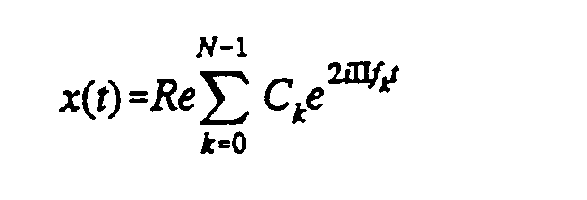
- B0 formé de porteuses k0 = 0 à 595, porteuses non émises ;
- B1 formé de porteuses k1 = 596 à 2345, à porteuses allouées à un premier programme ;
- B2 formé de porteuses k2 = 2346 à 4095, à porteuses allouées à un deuxième programme ;
- B3 formé de porteuses k3 = 4096 à 5845, à porteuses allouées à un troisième programme ;
- B4 formé de porteuses k4 = 5846 à 7595, à porteuses allouées à un quatrième programme ;
- B5 formé de porteuses k5 = 7596 à 8191, non émises.
Claims (13)
- Signal destiné à être transmis vers une pluralité de récepteurs, du type comprenant au moins deux signaux source autonomes et constitué d'une pluralité de fréquences porteuses sensiblement orthogonales modulées indépendamment, réparties sur une bande de fréquence déterminée (12),
caractérisé en ce que ladite bande de fréquence (12) est découpée en au moins deux sous-bandes de fréquence (131 à 134) comprenant chacune un jeu desdites fréquences porteuses sensiblement orthogonales (11), et en ce qu'on affecte à chacune desdites sous-bandes l'un desdits signaux source (Si), de façon qu'un récepteur puisse extraire du signal transmis, par filtrage, au moins une desdites sous-bandes et effectuer un traitement de démodulation uniquement sur les fréquences porteuses contenues dans les sous-bandes extraites. - Signal selon la revendication 1, caractérisé en ce que lesdites sous-bandes (131 à 134) sont jointives.
- Signal selon l'une quelconque des revendications 1 et 2, caractérisé en ce que lesdites sous-bandes (131 à 134) présentent des largeurs de bandes identiques.
- Signal selon l'une quelconque des revendications 1 à 3, caractérisé en ce que l'affectation desdits signaux source (Si) auxdites sous-bandes (131 à 134) est variable dans le temps, de façon à maximiser la diversité en fréquence.
- Signal selon la revendication 4, caractérisé en ce que ladite affectation est modifiée à chaque émission d'une trame dudit signal.
- Signal selon l'une quelconque des revendications 1 à 5, caractérisé en ce qu'au moins un premier desdits signaux source (Si) correspond à des informations de base d'un programme et au moins un second desdits signaux source (Si) correspond à des informations complémentaires desdites informations de base, de façon à définir au moins deux niveaux de qualité de récepteur :un premier niveau de qualité correspondant à des récepteurs capables de traiter uniquement la sous-bande correspondant audit premier signal source ; etun second niveau de qualité correspondant à des récepteurs capables de traiter les sous-bandes correspondant auxdits premier et second signaux source.
- Procédé d'émission d'un signal selon l'une quelconque des revendications 1 à 6, ledit signal étant destiné à être transmis vers une pluralité de récepteurs, signal du type comprenant au moins deux signaux source (Si) autonomes et constitué d'une pluralité de fréquences porteuses (11) sensiblement orthogonales modulées indépendamment, réparties sur une bande de fréquence déterminée (12),
caractérisé en ce qu'il comprend les étapes suivantes :affectation audit signal d'une bande de fréquence déterminée (12), dans laquelle est définie une pluralité de fréquences porteuses sensiblement orthogonales (11);découpage de ladite bande de fréquence (12) en au moins deux sous-bandes de fréquence (131 à 134), comprenant chacune un jeu desdites fréquences porteuses sensiblement orthogonales ;réception d'au moins deux signaux source (Si) autonomes à émettre ;affectation à chacun desdits signaux source d'une desdites sous-bandes de fréquence ;regroupement desdites sous-bandes, de façon à former ledit signal à émettre ; etémission dudit signal à émettre. - Procédé selon la revendication 7, caractérisé en ce que lesdites sous-bandes (131 à 134) sont jointives.
- Procédé selon l'une quelconque des revendications 7 et 8, caractérisé en ce que ladite étape de regroupement des sous-bandes est précédée d'une étape de codage indépendant (22i) et d'entrelacement fréquentiel et temporel (23i) de chacun desdits signaux source, de façon à obtenir un jeu de signaux codés destinés à moduler chacun une desdites fréquences porteuses de la sous-bande affectée audit signal source.
- Récepteur adapté à la réception d'un signal selon l'une quelconque des revendications 1 à 6 ou d'un signal émis suivant le procédé selon l'une quelconque des revendications 7 à 9,
ledit signal émis comprenant au moins deux signaux source (Si) autonomes et étant constitué d'une pluralité de fréquences porteuses (11) sensiblement orthogonales modulées indépendamment, réparties sur une bande de fréquence déterminée (12),
caractérisé en ce qu'il comprend :des moyens de sélection d'un programme donné, correspondant à au moins une sous-bandes (131 à 134) dudit signal émis, ce dernier étant découpé en au moins deux sous-bandes de fréquence (131 à 134), comprenant chacune un jeu desdites fréquences porteuses sensiblement orthogonales ; etdes moyens de transformation mathématique (47 ; 58) agissant sur les fréquences porteuses contenues dans la ou les sous-bandes sélectionnées. - Récepteur selon la revendication 10, caractérisé en ce que lesdits moyens de sélection comprennent des moyens de transposition analogique comprenant un premier oscillateur de transposition RF (43) et un second oscillateur de transposition FI (44), et des moyens de contrôle de la fréquence d'oscillation dudit premier et/ou dudit second oscillateur, en fonction de la ou des sous-bandes sélectionnées, de façon que celles-ci soient centrées sur une fréquence prédéterminée.
- Récepteur selon la revendication 10, caractérisé en ce que lesdits moyens de sélection comprennent des premiers moyens de transposition analogique (51, 52) et des seconds moyens de transposition numérique (54) variables en fonction de la ou des sous-bandes sélectionnées, et des moyens de sous-échantillonnage (56).
- Récepteur selon l'une quelconque des revendications 10 à 12, caractérisé en ce que lesdits moyens de transformation mathématique (47 ; 58) agissent sur un nombre de fréquences porteuses légèrement supérieur au nombre de fréquences porteuses contenues dans la ou les sous-bandes extraites, de façon à compenser l'imperfection due au filtrage d'extraction desdites sous-bandes.
Applications Claiming Priority (3)
| Application Number | Priority Date | Filing Date | Title |
|---|---|---|---|
| FR9407612 | 1994-06-16 | ||
| FR9407612A FR2721461B1 (fr) | 1994-06-16 | 1994-06-16 | Signal formé d'une pluralité de fréquences porteuses orthogonales organisé de façon à simplifier la réception d'un des signaux source le composant, procédé d'émission et récepteur correspondants. |
| PCT/FR1995/000775 WO1995034967A1 (fr) | 1994-06-16 | 1995-06-13 | Signal ofdm organise de façon a simplifier la reception |
Publications (2)
| Publication Number | Publication Date |
|---|---|
| EP0765549A1 EP0765549A1 (fr) | 1997-04-02 |
| EP0765549B1 true EP0765549B1 (fr) | 2002-02-27 |
Family
ID=9464476
Family Applications (1)
| Application Number | Title | Priority Date | Filing Date |
|---|---|---|---|
| EP95923378A Expired - Lifetime EP0765549B1 (fr) | 1994-06-16 | 1995-06-13 | Signal ofdm organise de facon a simplifier la reception |
Country Status (6)
| Country | Link |
|---|---|
| US (2) | US6282167B1 (fr) |
| EP (1) | EP0765549B1 (fr) |
| JP (1) | JP3827718B2 (fr) |
| DE (1) | DE69525624T2 (fr) |
| FR (1) | FR2721461B1 (fr) |
| WO (1) | WO1995034967A1 (fr) |
Families Citing this family (68)
| Publication number | Priority date | Publication date | Assignee | Title |
|---|---|---|---|---|
| FR2721461B1 (fr) * | 1994-06-16 | 1996-09-06 | France Telecom | Signal formé d'une pluralité de fréquences porteuses orthogonales organisé de façon à simplifier la réception d'un des signaux source le composant, procédé d'émission et récepteur correspondants. |
| KR100648475B1 (ko) * | 1996-01-29 | 2007-01-31 | 소니 가부시끼 가이샤 | 통신자원할당방법및장치 |
| JPH09321721A (ja) * | 1996-05-27 | 1997-12-12 | Sony Corp | 送信方法,送信装置,受信方法及び受信装置 |
| JPH1066039A (ja) * | 1996-08-23 | 1998-03-06 | Sony Corp | 通信方法、送信装置、送信方法、受信装置及び受信方法 |
| CA2214934C (fr) | 1996-09-24 | 2001-10-30 | At&T Corp. | Methode et appareil de communication mobile de donnees |
| FR2757725B1 (fr) * | 1996-12-20 | 2001-10-05 | Thomson Csf | Procede hierarchique de transmission et de radiodiffusion numerique d'emission radiophoniques |
| DE19718492A1 (de) * | 1997-05-02 | 1998-11-05 | Bosch Gmbh Robert | Verfahren zur Übertragung von Daten mit einem Multiträgerübertragungsverfahren |
| FR2768278B1 (fr) * | 1997-09-11 | 1999-11-26 | France Telecom | Procede d'estimation d'un decalage de phase parasite lors de la reception d'un signal multiporteuse, et recepteur correspondant |
| US5955992A (en) * | 1998-02-12 | 1999-09-21 | Shattil; Steve J. | Frequency-shifted feedback cavity used as a phased array antenna controller and carrier interference multiple access spread-spectrum transmitter |
| US7430257B1 (en) * | 1998-02-12 | 2008-09-30 | Lot 41 Acquisition Foundation, Llc | Multicarrier sub-layer for direct sequence channel and multiple-access coding |
| JP4284568B2 (ja) | 1999-03-18 | 2009-06-24 | ソニー株式会社 | 受信装置および方法、並びに記録媒体 |
| US6937665B1 (en) * | 1999-04-19 | 2005-08-30 | Interuniversitaire Micron Elektronica Centrum | Method and apparatus for multi-user transmission |
| US6930989B1 (en) * | 2000-06-20 | 2005-08-16 | Cisco Technology, Inc. | Wide frequency offset correction using encoded interburst phase differences |
| US6970416B1 (en) * | 2000-07-07 | 2005-11-29 | Telecommunications Research Laboratories | OFDM system with simple terminals |
| FR2815492B1 (fr) * | 2000-10-13 | 2003-02-14 | Thomson Csf | Systeme et procede de radiodiffusion assurant une continuite de service |
| US8670390B2 (en) | 2000-11-22 | 2014-03-11 | Genghiscomm Holdings, LLC | Cooperative beam-forming in wireless networks |
| US7203158B2 (en) | 2000-12-06 | 2007-04-10 | Matsushita Electric Industrial Co., Ltd. | OFDM signal transmission system, portable terminal, and e-commerce system |
| US6961545B2 (en) | 2001-04-09 | 2005-11-01 | Atheros Communications, Inc. | Method and system for providing antenna diversity |
| US10931338B2 (en) | 2001-04-26 | 2021-02-23 | Genghiscomm Holdings, LLC | Coordinated multipoint systems |
| US9819449B2 (en) | 2002-05-14 | 2017-11-14 | Genghiscomm Holdings, LLC | Cooperative subspace demultiplexing in content delivery networks |
| US9893774B2 (en) | 2001-04-26 | 2018-02-13 | Genghiscomm Holdings, LLC | Cloud radio access network |
| US10355720B2 (en) | 2001-04-26 | 2019-07-16 | Genghiscomm Holdings, LLC | Distributed software-defined radio |
| US10425135B2 (en) | 2001-04-26 | 2019-09-24 | Genghiscomm Holdings, LLC | Coordinated multipoint systems |
| FR2825860B1 (fr) * | 2001-06-06 | 2005-03-18 | St Microelectronics Sa | Transmission de donnees en maitre-esclave en multiplexage par division de frequences orthogonales |
| FR2825861A1 (fr) * | 2001-06-06 | 2002-12-13 | St Microelectronics Sa | Allocation de frequences en modulation multiporteuses orthogonales |
| FR2826208B1 (fr) * | 2001-06-19 | 2003-12-05 | Thales Sa | Systeme et procede de transmission d'un signal audio ou phonie |
| WO2003013049A1 (fr) * | 2001-07-19 | 2003-02-13 | Siemens Aktiengesellschaft | Distribution de sous-porteuses d'un systeme a plusieurs porteuses pour terminaux a faible debit |
| US6951163B1 (en) * | 2001-10-05 | 2005-10-04 | Nordson Corporation | Shaft coupling and shifting mechanism for pneumatic pump |
| US10644916B1 (en) | 2002-05-14 | 2020-05-05 | Genghiscomm Holdings, LLC | Spreading and precoding in OFDM |
| US10142082B1 (en) | 2002-05-14 | 2018-11-27 | Genghiscomm Holdings, LLC | Pre-coding in OFDM |
| US10200227B2 (en) | 2002-05-14 | 2019-02-05 | Genghiscomm Holdings, LLC | Pre-coding in multi-user MIMO |
| US9628231B2 (en) | 2002-05-14 | 2017-04-18 | Genghiscomm Holdings, LLC | Spreading and precoding in OFDM |
| US7724639B1 (en) * | 2002-12-12 | 2010-05-25 | Entropic Communications, Inc. | Method of bit allocation in a multicarrier symbol to achieve non-periodic frequency diversity |
| CN100544239C (zh) * | 2003-02-14 | 2009-09-23 | 华为技术有限公司 | 用于正交频分复用通信的交织方法 |
| CN101677309B (zh) * | 2003-02-14 | 2013-11-06 | 华为技术有限公司 | 发射机、交织器和交织方法 |
| US7221680B2 (en) * | 2003-09-02 | 2007-05-22 | Qualcomm Incorporated | Multiplexing and transmission of multiple data streams in a wireless multi-carrier communication system |
| US8599764B2 (en) | 2003-09-02 | 2013-12-03 | Qualcomm Incorporated | Transmission of overhead information for reception of multiple data streams |
| US8477809B2 (en) | 2003-09-02 | 2013-07-02 | Qualcomm Incorporated | Systems and methods for generalized slot-to-interlace mapping |
| US8509051B2 (en) | 2003-09-02 | 2013-08-13 | Qualcomm Incorporated | Multiplexing and transmission of multiple data streams in a wireless multi-carrier communication system |
| BRPI0415840A (pt) * | 2003-10-24 | 2007-01-02 | Qualcomm Inc | multiplexação por divisão de freqüência de múltiplos fluxos de dados em um sistema de comunicação de multi-portadora sem fio |
| US8526412B2 (en) * | 2003-10-24 | 2013-09-03 | Qualcomm Incorporated | Frequency division multiplexing of multiple data streams in a wireless multi-carrier communication system |
| US7665008B2 (en) * | 2004-01-12 | 2010-02-16 | Intel Corporation | Method and apparatus for implementing a low density parity check code in a wireless system |
| US7345989B2 (en) * | 2004-01-12 | 2008-03-18 | Intel Corporation | Adaptive channelization scheme for high throughput multicarrier systems |
| US7551545B2 (en) * | 2004-02-09 | 2009-06-23 | Qualcomm Incorporated | Subband-based demodulation for an OFDM-based communication system |
| US7751305B2 (en) * | 2004-06-25 | 2010-07-06 | Samsung Electronics Co., Ltd. | Method for transmitting and receiving broadcast service data in an OFDMA wireless communication system |
| US11552737B1 (en) | 2004-08-02 | 2023-01-10 | Genghiscomm Holdings, LLC | Cooperative MIMO |
| US11381285B1 (en) | 2004-08-02 | 2022-07-05 | Genghiscomm Holdings, LLC | Transmit pre-coding |
| US11184037B1 (en) | 2004-08-02 | 2021-11-23 | Genghiscomm Holdings, LLC | Demodulating and decoding carrier interferometry signals |
| US7848458B2 (en) | 2005-02-18 | 2010-12-07 | Mitsubishi Electric Corporation | Communication apparatus |
| WO2006092856A1 (fr) * | 2005-03-02 | 2006-09-08 | Fujitsu Limited | Procede de communication a porteuses multiples et station de base et station mobile utilisees pour ce procede |
| US8077692B2 (en) | 2005-05-20 | 2011-12-13 | Qualcomm Incorporated | Enhanced frequency division multiple access for wireless communication |
| US7933344B2 (en) * | 2006-04-25 | 2011-04-26 | Mircosoft Corporation | OFDMA based on cognitive radio |
| US8189621B2 (en) | 2006-05-12 | 2012-05-29 | Microsoft Corporation | Stack signaling to application with lack of requested bandwidth |
| US8144793B2 (en) | 2006-12-12 | 2012-03-27 | Microsoft Corporation | Cognitive multi-user OFDMA |
| US7929623B2 (en) * | 2007-03-30 | 2011-04-19 | Microsoft Corporation | FEC in cognitive multi-user OFDMA |
| US7970085B2 (en) | 2007-05-08 | 2011-06-28 | Microsoft Corporation | OFDM transmission and reception for non-OFDMA signals |
| US20090175210A1 (en) * | 2007-07-26 | 2009-07-09 | Qualcomm Incorporated | Multiplexing and transmission of multiple data streams in a wireless multi-carrier communication system |
| US8374130B2 (en) | 2008-01-25 | 2013-02-12 | Microsoft Corporation | Orthogonal frequency division multiple access with carrier sense |
| US8855087B2 (en) * | 2008-12-18 | 2014-10-07 | Microsoft Corporation | Wireless access point supporting control by multiple applications |
| US20150117399A1 (en) * | 2013-10-29 | 2015-04-30 | Qualcomm Incorporated | Baton handover with receive diversity in td-scdma |
| US12224860B1 (en) | 2014-01-30 | 2025-02-11 | Genghiscomm Holdings, LLC | Linear coding in decentralized networks |
| US10637705B1 (en) | 2017-05-25 | 2020-04-28 | Genghiscomm Holdings, LLC | Peak-to-average-power reduction for OFDM multiple access |
| US10243773B1 (en) | 2017-06-30 | 2019-03-26 | Genghiscomm Holdings, LLC | Efficient peak-to-average-power reduction for OFDM and MIMO-OFDM |
| US11343823B2 (en) | 2020-08-16 | 2022-05-24 | Tybalt, Llc | Orthogonal multiple access and non-orthogonal multiple access |
| US11917604B2 (en) | 2019-01-25 | 2024-02-27 | Tybalt, Llc | Orthogonal multiple access and non-orthogonal multiple access |
| US12206535B1 (en) | 2018-06-17 | 2025-01-21 | Tybalt, Llc | Artificial neural networks in wireless communication systems |
| CN113454964A (zh) | 2019-01-25 | 2021-09-28 | 珍吉斯科姆控股有限责任公司 | 正交多址和非正交多址 |
| WO2020242898A1 (fr) | 2019-05-26 | 2020-12-03 | Genghiscomm Holdings, LLC | Accès multiple non orthogonal |
Family Cites Families (8)
| Publication number | Priority date | Publication date | Assignee | Title |
|---|---|---|---|---|
| FR2609228B1 (fr) * | 1986-12-24 | 1989-12-01 | France Etat | Procede de diffusion numerique dans des canaux de television |
| FR2658017B1 (fr) * | 1990-02-06 | 1992-06-05 | France Etat | Procede de diffusion de donnees numeriques, notamment pour la radiodiffusion a haut debit vers des mobiles, a entrelacement temps-frequence et aide a l'acquisition de la commande automatique de frequence, et recepteur correspondant. |
| ATE133820T1 (de) * | 1990-11-05 | 1996-02-15 | Philips Electronics Nv | Digitales übertragungssystem, gerät zur aufnahme und/oder wiedergabe und sender sowie empfänger zur anwendung im übertragungssystem |
| KR100263599B1 (ko) * | 1991-09-02 | 2000-08-01 | 요트.게.아. 롤페즈 | 인코딩 시스템 |
| US5282222A (en) * | 1992-03-31 | 1994-01-25 | Michel Fattouche | Method and apparatus for multiple access between transceivers in wireless communications using OFDM spread spectrum |
| GB9209027D0 (en) * | 1992-04-25 | 1992-06-17 | British Aerospace | Multi purpose digital signal regenerative processing apparatus |
| EP1035694B9 (fr) * | 1992-09-25 | 2005-01-12 | Matsushita Electric Industrial Co., Ltd. | Système de transmission à résolutions multiples |
| FR2721461B1 (fr) * | 1994-06-16 | 1996-09-06 | France Telecom | Signal formé d'une pluralité de fréquences porteuses orthogonales organisé de façon à simplifier la réception d'un des signaux source le composant, procédé d'émission et récepteur correspondants. |
-
1994
- 1994-06-16 FR FR9407612A patent/FR2721461B1/fr not_active Expired - Lifetime
-
1995
- 1995-06-13 US US08/765,162 patent/US6282167B1/en not_active Expired - Lifetime
- 1995-06-13 JP JP50173296A patent/JP3827718B2/ja not_active Expired - Lifetime
- 1995-06-13 WO PCT/FR1995/000775 patent/WO1995034967A1/fr not_active Ceased
- 1995-06-13 DE DE69525624T patent/DE69525624T2/de not_active Expired - Lifetime
- 1995-06-13 EP EP95923378A patent/EP0765549B1/fr not_active Expired - Lifetime
-
2001
- 2001-07-31 US US09/919,009 patent/US6810006B2/en not_active Expired - Lifetime
Also Published As
| Publication number | Publication date |
|---|---|
| FR2721461A1 (fr) | 1995-12-22 |
| WO1995034967A1 (fr) | 1995-12-21 |
| US6282167B1 (en) | 2001-08-28 |
| US20020060984A1 (en) | 2002-05-23 |
| EP0765549A1 (fr) | 1997-04-02 |
| JP3827718B2 (ja) | 2006-09-27 |
| DE69525624T2 (de) | 2002-10-31 |
| DE69525624D1 (de) | 2002-04-04 |
| JPH10503894A (ja) | 1998-04-07 |
| US6810006B2 (en) | 2004-10-26 |
| FR2721461B1 (fr) | 1996-09-06 |
Similar Documents
| Publication | Publication Date | Title |
|---|---|---|
| EP0765549A1 (fr) | Signal ofdm organise de fa on a simplifier la reception | |
| EP0278192B1 (fr) | Procédé de diffusion numérique dans des canaux de télévision | |
| EP0441730B1 (fr) | Procédé de diffusion de données à entrelacement temps-fréquence utilisant des signaux de référence de fréquence | |
| EP0608024B1 (fr) | Système de transmission avec récupération de rythme | |
| FR2829642A1 (fr) | Signal multiporteuses, procede de poursuite d'un canal de transmission a partir d'un tel signal et dispositif pour sa mise en oeuvre | |
| CA2524224C (fr) | Procede de transmission de donnees par courant porteur | |
| EP0600193B1 (fr) | Procédé de diffusion de données numériques, notamment pour la radiodiffusion à haut débit vers des mobiles, à entrelacement temps-fréquence | |
| EP0616445B1 (fr) | Système de radiocommunication numérique bidirectionnel multiporteuse, station mobile et station de base correspondantes | |
| EP0631406B1 (fr) | Signal numérique apte à être reçu par des récepteurs à démodulateur de signaux modulés en amplitude à bande latérale réduite, procédé de transmission, procédé de réception, dispositif de réception et utilisation correspondants | |
| WO2008007028A2 (fr) | Procédés de réception et d'émission d'un signal multiporteuse comprenant un préambule comprenant des éléments de données, dispositifs et produits programme d'ordinateur correspondants | |
| WO1992006545A1 (fr) | Demodulateur multiporteuses | |
| FR2826208A1 (fr) | Systeme et procede de transmission d'un signal audio ou phonie | |
| FR2903833A1 (fr) | Procedes d'emission et de reception d'un signal multiporteuse mettant en oeuvre une estimation de canal, dispositifs et produits programme d'ordinateur correspondants. | |
| EP0742654B1 (fr) | Signal numérique multiporteuse limitant les brouillages cocanaux avec un signal de télévision analogique | |
| EP0944979B1 (fr) | Procede de transmission ou de radiodiffusion numerique | |
| FR2757725A1 (fr) | Procede hierarchique de transmission et de radiodiffusion numerique d'emission radiophoniques | |
| FR3150378A1 (fr) | Procédé et dispositif de réception d’au moins un mot binaire transmis sur un ensemble de sous-porteuses OFDM | |
| WO2024261050A1 (fr) | Procédé et dispositif de transmission d'une trame de données en ofdm | |
| EP3059892B1 (fr) | Procédé de transmission d'un plan de fréquences dans un système de télécommunication | |
| FR2905814A1 (fr) | Procede de reception de signaux modules en amrf et dispositif de reception mettant en oeuvre ce procede. |
Legal Events
| Date | Code | Title | Description |
|---|---|---|---|
| PUAI | Public reference made under article 153(3) epc to a published international application that has entered the european phase |
Free format text: ORIGINAL CODE: 0009012 |
|
| 17P | Request for examination filed |
Effective date: 19961230 |
|
| AK | Designated contracting states |
Kind code of ref document: A1 Designated state(s): DE GB IT |
|
| GRAG | Despatch of communication of intention to grant |
Free format text: ORIGINAL CODE: EPIDOS AGRA |
|
| 17Q | First examination report despatched |
Effective date: 20010711 |
|
| GRAG | Despatch of communication of intention to grant |
Free format text: ORIGINAL CODE: EPIDOS AGRA |
|
| GRAH | Despatch of communication of intention to grant a patent |
Free format text: ORIGINAL CODE: EPIDOS IGRA |
|
| GRAH | Despatch of communication of intention to grant a patent |
Free format text: ORIGINAL CODE: EPIDOS IGRA |
|
| REG | Reference to a national code |
Ref country code: GB Ref legal event code: IF02 |
|
| GRAA | (expected) grant |
Free format text: ORIGINAL CODE: 0009210 |
|
| AK | Designated contracting states |
Kind code of ref document: B1 Designated state(s): DE GB IT |
|
| REF | Corresponds to: |
Ref document number: 69525624 Country of ref document: DE Date of ref document: 20020404 |
|
| GBT | Gb: translation of ep patent filed (gb section 77(6)(a)/1977) |
Effective date: 20020514 |
|
| PLBE | No opposition filed within time limit |
Free format text: ORIGINAL CODE: 0009261 |
|
| STAA | Information on the status of an ep patent application or granted ep patent |
Free format text: STATUS: NO OPPOSITION FILED WITHIN TIME LIMIT |
|
| 26N | No opposition filed |
Effective date: 20021128 |
|
| PGFP | Annual fee paid to national office [announced via postgrant information from national office to epo] |
Ref country code: GB Payment date: 20140527 Year of fee payment: 20 |
|
| PGFP | Annual fee paid to national office [announced via postgrant information from national office to epo] |
Ref country code: DE Payment date: 20140523 Year of fee payment: 20 Ref country code: IT Payment date: 20140530 Year of fee payment: 20 |
|
| REG | Reference to a national code |
Ref country code: DE Ref legal event code: R071 Ref document number: 69525624 Country of ref document: DE |
|
| REG | Reference to a national code |
Ref country code: GB Ref legal event code: PE20 Expiry date: 20150612 |
|
| PG25 | Lapsed in a contracting state [announced via postgrant information from national office to epo] |
Ref country code: GB Free format text: LAPSE BECAUSE OF EXPIRATION OF PROTECTION Effective date: 20150612 |