EP0763995B1 - Filtriergerät - Google Patents
Filtriergerät Download PDFInfo
- Publication number
- EP0763995B1 EP0763995B1 EP95921009A EP95921009A EP0763995B1 EP 0763995 B1 EP0763995 B1 EP 0763995B1 EP 95921009 A EP95921009 A EP 95921009A EP 95921009 A EP95921009 A EP 95921009A EP 0763995 B1 EP0763995 B1 EP 0763995B1
- Authority
- EP
- European Patent Office
- Prior art keywords
- plunger
- skirt portion
- receptacle
- liquid
- filter
- Prior art date
- Legal status (The legal status is an assumption and is not a legal conclusion. Google has not performed a legal analysis and makes no representation as to the accuracy of the status listed.)
- Expired - Lifetime
Links
- 239000007788 liquid Substances 0.000 claims abstract description 40
- 238000001914 filtration Methods 0.000 claims abstract description 20
- 239000011521 glass Substances 0.000 claims description 8
- 239000011347 resin Substances 0.000 claims description 5
- 229920005989 resin Polymers 0.000 claims description 5
- 239000004743 Polypropylene Substances 0.000 claims description 3
- 239000004417 polycarbonate Substances 0.000 claims description 3
- 229920000515 polycarbonate Polymers 0.000 claims description 3
- -1 polypropylene Polymers 0.000 claims description 3
- 229920001155 polypropylene Polymers 0.000 claims description 3
- 239000000463 material Substances 0.000 description 13
- 238000007789 sealing Methods 0.000 description 11
- XLYOFNOQVPJJNP-UHFFFAOYSA-N water Substances O XLYOFNOQVPJJNP-UHFFFAOYSA-N 0.000 description 10
- 235000013361 beverage Nutrition 0.000 description 8
- 239000000203 mixture Substances 0.000 description 6
- 230000008901 benefit Effects 0.000 description 3
- 241001122767 Theaceae Species 0.000 description 2
- 230000009471 action Effects 0.000 description 2
- 230000000694 effects Effects 0.000 description 2
- 238000000034 method Methods 0.000 description 2
- 239000011343 solid material Substances 0.000 description 2
- 230000003213 activating effect Effects 0.000 description 1
- 238000001816 cooling Methods 0.000 description 1
- JXSJBGJIGXNWCI-UHFFFAOYSA-N diethyl 2-[(dimethoxyphosphorothioyl)thio]succinate Chemical compound CCOC(=O)CC(SP(=S)(OC)OC)C(=O)OCC JXSJBGJIGXNWCI-UHFFFAOYSA-N 0.000 description 1
- 230000006870 function Effects 0.000 description 1
- 238000001746 injection moulding Methods 0.000 description 1
- 239000002184 metal Substances 0.000 description 1
- 230000004048 modification Effects 0.000 description 1
- 238000012986 modification Methods 0.000 description 1
- 239000002245 particle Substances 0.000 description 1
- 230000002093 peripheral effect Effects 0.000 description 1
- 238000002360 preparation method Methods 0.000 description 1
- 239000007787 solid Substances 0.000 description 1
- 239000012265 solid product Substances 0.000 description 1
Images

Classifications
-
- A—HUMAN NECESSITIES
- A47—FURNITURE; DOMESTIC ARTICLES OR APPLIANCES; COFFEE MILLS; SPICE MILLS; SUCTION CLEANERS IN GENERAL
- A47J—KITCHEN EQUIPMENT; COFFEE MILLS; SPICE MILLS; APPARATUS FOR MAKING BEVERAGES
- A47J31/00—Apparatus for making beverages
- A47J31/18—Apparatus in which ground coffee or tea-leaves are immersed in the hot liquid in the beverage container
- A47J31/20—Apparatus in which ground coffee or tea-leaves are immersed in the hot liquid in the beverage container having immersible, e.g. rotatable, filters
Definitions
- the present invention relates to filter apparatus and in particular, but not exclusively, to filter apparatus for the preparation of beverages such as coffee.
- a plunger is inserted into the receptacle and pushed downwardly through the liquid in the receptacle from an upper opening of the receptacle to a base region of the receptacle.
- the plunger includes a plunger head which has a filter element and this serves to filter the liquid during the movement of the plunger downwardly within the receptacle. This downward movement of the plunger, with its associated filter element, seeks to collect, and retain, coffee grinds and other solid particles that should be kept separate from the beverage to be eventually dispensed.
- Such known apparatus is however disadvantageous in that the plunger does not successfully prevent the passage of coffee grinds, and other material, into the region of the receptacle from which the beverage is eventually dispensed.
- the build-up of pressure in the liquid below the downwardly moving plunger serves to open an access path for coffee grinds and other material to by-pass the plunger, i.e. pass through a gap formed between the outer periphery of the plunger and the inner surface of the receptacle.
- Metal filter plunger members are commonly known but are restricted in their use since it is generally not feasible to use such filter plunger members with polycarbonate beakers which tend to exhibit a decrease in internal diameter with depth.
- NL-A-9001463 discloses a filter apparatus (cf. preamble of Claims 1 and 12) comprising a receptacle for liquid to be filtered, the receptacle having an outlet from which filtered liquid can be dispensed, and a plunger movable downwardly within said receptacle and through the liquid, the plunger having filter means arranged to filter said liquid during the downward, filtering movement of the plunger, said plunger having a cylindrical skirt portion in contact with the inner surface of said receptacle, wherein said skirt portion depends downwardly from said filter means in the direction of the filtering movement of said plunger, said skirt portion being arranged to be biased towards the inner surface of said receptacle by the pressure of the liquid being filtered during said filtering movement.
- the plunger of this known filter apparatus is not designed for use with a receptacle which is narrower towards its base. Furthermore, the skirt portion may become deformed due to continued use.
- the present invention seeks to provide filter apparatus having advantages over filter apparatus of the type defined.
- filter apparatus of the type defined is characterised in that said skirt portion of said plunger has thermally activated memory characteristics enabling the skirt portion to be returned to its original diameter.
- the liquid being filtered acts to force the skirt region of the plunger outwardly and into contact with the inner surface of the receptacle and this assists in seeking to greatly inhibit the passage of any solid material past the outer periphery of the plunger means.
- the improved sealing between the plunger means and the inner surface of the receptacle substantially reduces the amount of solid product found in the filtered liquid.
- said skirt portion is arranged to flair outwardly from the filter means during said movement of said plunger means through said liquid.
- the skirt portion may then be arranged to be formed from an appropriate material to allow for such flaring-out so as to assist in providing a high quality seal between the outer periphery of the plunger means and the inner surface of said receptacle.
- said skirt means is provided with a plurality of lines of weakness so as to assist in the basing thereof towards the inner surface of said receptacle.
- said lines of weakness comprise a plurality of slits formed in said skirt portion.
- said slits extend from the edge of said skirt means remote from said filter means and serve to provide a plurality of tongue portions on said skirt portion.
- each of said plurality of tongue portions is arranged to be biased towards the inner surface of said receptacle so as to provide improved sealing.
- Such biasing is readily achieved by virtue of the pressure of the liquid within the skirt portion.
- each of the tongue portions is arranged to have substantially the same dimensions.
- each of said slits can be arranged to extend for the same distance into said skirt portion.
- each of said slits extends for substantially half the height of said skirt portion.
- said skirt portion is formed from a glass-based resin.
- a glass-based resin is particularly advantageous in providing for a skirt portion which can be readily biased in the appropriate manner by virtue of the pressure of the liquid being filtered.
- an advantageous material is glass-filled polypropylene.
- Materials of the above-mentioned type exhibit advantageous characteristics as regards flexibility and resilience.
- apparatus of the present invention may comprise a receptacle which is arranged to dispense a filtered beverage.
- embodiments of the invention may comprise a plunge-filter beverage maker such as a plunge-filter coffee maker or a plunge-filter tea maker.
- said apparatus may comprise a lid having an aperture through which a shaft of said plunger extends and by virtue of which said shaft member is guided during the filtering movement of said plunger.
- Said lid preferably forms a snap-fit with an opening of said receptacle.
- the snap-fit of the lid on the receptacle provides stable guide means for the passage of the plunger shaft and thus for the plunger itself.
- a plunger for a filter apparatus said plunger having a filter means for the filtering of a liquid during movement of the plunger through said liquid, wherein said plunger has a cylindrical skirt portion for contacting an inner surface of a receptacle containing the liquid to be filtered, said skirt portion extending away from said filter means in a direction of intended movement of said plunger during filtering of said liquid, and wherein said skirt portion is arranged to be biased towards the inner surface of said receptacle by pressure of the liquid being filtered during said filtering movement, and characterised in that said skirt portion of said plunger has thermally activated memory characteristics enabling the skirt portion to be returned to its original diameter.
- said skirt portion is provided with a plurality of lines of weakness so as to assist in the biasing thereof towards the inner surface of said receptacle.
- said lines of weakness comprise a plurality of slits formed in said skirt portion.
- said slits extend from the edge of said skirt portion remote from said filter means and serve to provide a plurality of tongue portions on said skirt portion.
- each of said plurality of tongue portions is arranged to be biased towards the inner surface of said receptacle so as to provide for the improved sealing achieved by the present invention.
- Such biasing can be readily achieved by virtue of the pressure of the liquid within the skirt portion.
- each of the tongue portions is arranged to have substantially the same dimensions.
- each of said slits may be arranged to extend for the same distance into said skirt portion.
- each of said slits extends for substantially half the height of said skirt portion.
- said skirt portion is formed from a glass-based resin.
- a glass-based resin is particularly advantageous in providing for a skirt portion which can be readily biased in the appropriate manner by virtue of the pressure of the liquid being filtered.
- an advantageous material is glass-filled polypropylene.
- each of the aspects of the present invention may readily relate to a plunger-filter coffee or tea maker, or to a plunger therefor.
- the illustrated embodiment of the present invention comprises a plunge-filter coffee maker 10 having a beaker 12 formed of polycarbonate. Coffee is formed in the beaker by the mixture of hot water and ground coffee therein and, when appropriate, can be dispensed by way of a spout 14.
- the handle 16 is rigidly connected to the beaker 12 by way of lugs 18 which extend outwardly from the outer surface of the beaker 12.
- the handle 16 is formed from a material which, when cooling, is arranged to shrink-fit around the lugs 18.
- the coffee maker 10 also includes a lid 20 which is arranged to snap-fit onto the upper periphery of the beaker 12 and is provided with a central bore through which a shaft 22 of a plunger extends for guidance therethrough. At the lower end of the shaft 22 as illustrated in the drawings, there is provided a plunger head 24 and at the upper end there is provided a button handle 26.
- the lid 20 can be fitted onto the upper periphery of the beaker 12 and the button handle 26 of the plunger can be moved downwardly so as to move the plunger 24 from a position adjacent the lid 20, and in the direction of arrow A in Figure 1, downwardly through the hot water and ground coffee mixture so as to provide for filtered coffee in the region above the plunger head 24 which can then be dispensed by way of the spout 14.
- the plunger head 24 includes a skirt portion 28 around the periphery thereof which is arranged to extend away from a filter element (not shown in Figure 1) mounted in the plunger head 24 and in the direction of movement of the plunger head during the filtering action.
- the skirt portion 28 is arranged to depend downwardly from the filter element (not shown in Figure 1).
- the plunger head 24 is circular in form and has a shallow cylindrical portion extending downwardly to form the aforementioned skirt portion 28.
- the skirt portion 28 is provided with a plurality of slits 32 which extend upwardly from the lower surface of the skirt portion 28 and for a distance which is substantially all to half the height of the skirt portion 28.
- the plurality of slits 32 serve to define a plurality of adjacent tongue portions 30 which are arranged for hinged movement related to the upper portion of the skirt portion.
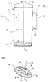
- a flat circular filter element 34 is provided in the plunger head 24 so as to provide for the filtering of the hot water and ground coffee mixture during the downward movement of the plunger head 24 in the direction of arrow A of Figure 1.
- the shaft 22 is received in a central mounting portion of the plunger head 24 from which said central mounting portion support ribs 36 extend in a radial manner.
- the support ribs 36 extend so as to provide support for the filter element 34 and extend between the central mounting portion of the plunger head 24 to receive the shaft 22 and an outer annular portion of the plunger head 24 from which the skirt portion 28 depends.
- Figure 3 shows a cross-section of the plunger head 24 of Figure 2 taken along the lines III-III.
- the radially extending support ribs 36 extend through the filter element 34 so that a lower portion 36a of each rib extends below the filter element 34.
- the plunger head 24 of the illustrated embodiment of the present invention is now described. As mentioned above, in order to form the filtered coffee, the plunger head 24 is moved downwardly through the hot water and ground coffee mixture in the beaker 12 and in the direction of arrow A in Figure 1. During such movement, there is a build up of pressure in the hot water ground coffee mixture below the plunger head 24 which serves to resist movement of the plunger head 24 in the direction of arrow A.
- the configuration of the plunger head 24 is arranged to benefit from such a build up of pressure in order to improve the sealing of the peripheral portion of the plunger head 24 with the inner surface of the beaker 12.
- Such an improved sealing is particularly required so as to prevent the passage of coffee grinds, and other undesired material, into the coffee that is to be dispensed by way of the spout 14.
- the aforementioned sealing is achieved in the illustrated embodiment without the need for any biasing means such as a spring member commonly found in known beakers.
- the water located below the plunger head 24 serves to bias the downwardly depending skirt portion 28 in a direction towards the inner surface of the beaker 12, that is, in the direction of arrows B shown in Figure 3.
- the aforementioned increase in the water pressure serves to deflect substantially all of the tongue portions 30 towards, and into sealing engagement with, the inner surface of the beaker 12.
- the improved sealing between the outer periphery of the plunger head 24 and the inner surface of the beaker 12 as provided by the illustrated embodiment of the present invention, is particularly advantageous in serving to inhibit the passage of coffee grinds and other unwanted material into the coffee to be dispensed.
- the plunger head 24 serves to reduce the likelihood of the inner surface of the beaker 12 becoming scratched or otherwise spoilt by coffee grinds or other material that, in known coffee makers, can become trapped between the outer portion of the plunger head and the inner surface of the beaker during the movement of the plunger.
- a further advantage for providing the sealing between the outer periphery of the plunger head 24 and the inner surface of the beaker 12 arises from the slight narrowing of the beaker 12 towards the bottom thereof.
- the diameter of the beaker 12 is slightly greater at the top portion adjacent to the lid 20 than it is at the base portion.
- Such narrowing can be readily provided in a beaker 12 formed by an injection moulding process and the skirt portion 28 can advantageously follow any variation in diameter of the beaker without detriment to the aforementioned sealing feature.
- the skirt portion 28 is arranged to return to its larger diameter once immersed in suitably hot water. Then, if the skirt becomes deformed due to continued use, or otherwise, it can be returned to its original diameter by thermally activating its memory characteristics which allow for its return to its original diameter.
- FIG 4 is a cross-section through the lid 20 and upper portions of the beaker 12 shown in Figure 1 from which it can be clearly seen that the lid 20 is arranged to snap-fit onto the upper periphery wall of the beaker 12.
- Such snap-fitment particularly when the beaker is formed of glass-filled resin, proves advantageous in providing for a secure mounting of the plunger shaft 22 within the coffee maker 10.
- the snap-fitment of the lid 20 onto the beaker 12 provides for particular stability between the lid 20 and the beaker 12 and thereby provides for particular stability in the location of a guide bore extending upwardly through the central portion of the lid 20 and through which the shaft 22 of the plunger extends.
- the shaft 22, and thus the plunger itself can be accurately directed in a manner such that the shaft 22 extends along in a direction parallel to the longitudinal axis of the beaker 12 and that the plane of the filter element 34 and the transverse portion of the plunger head 24 is substantially perpendicular to the wall of the beaker 12.
- the sealing between the outer periphery of the plunger head 24 and the inner surface of the beaker 12 can thereby be particularly enhanced by the snap-fitment of the lid 20 to the beaker 12.
- the filter apparatus of the present invention can be incorporated into any nature of beaker requiring a filter plunger to move therethrough so as to effect filtration of liquid.
- the invention can be incorporated into any form of plunge-filter apparatus for preparing beverages.
- the configuration of the plunger head is not restricted to the details of the foregoing embodiment in that any appropriate form of skirt portion 28 can be provided so long as it extends in a direction of movement of the plunger head and it can be biased into engagement with the inner surface of the beaker by way of the increase in liquid pressure that occurs in the liquid to be filtered.
Landscapes
- Engineering & Computer Science (AREA)
- Food Science & Technology (AREA)
- Apparatus For Making Beverages (AREA)
- Separation By Low-Temperature Treatments (AREA)
- Control And Other Processes For Unpacking Of Materials (AREA)
- Water Treatment By Sorption (AREA)
- Electrical Discharge Machining, Electrochemical Machining, And Combined Machining (AREA)
- Filtration Of Liquid (AREA)
Claims (13)
- Filtervorrichtung mit einem Behälter (12) für zu filternde Flüssigkeit, wobei der Behälter einen Auslaß (14) hat, von dem gefilterte Flüssigkeit ausgegeben werden kann, und einem Kolben (22, 24), der innerhalb des Behälters und durch die Flüssigkeit nach unten bewegbar ist, wobei der Kolben eine Filtereinrichtung (34) hat, die dazu eingerichtet ist, die Flüssigkeit während der nach unten gerichteten, filternden Bewegung des Kolbens zu filtern, wobei der Kolben ein zylindrisches Schürzenteil (28) in Kontakt mit der inneren Oberfläche des Behälters hat, wobei sich das Schürzenteil (28) von der Filtereinrichtung in der Richtung der filternden Bewegung des Kolbens nach unten erstreckt, wobei das Schürzenteil (28) dazu eingerichtet ist, während der filternden Bewegung durch den Druck der gefilterten Flüssigkeit gegen die innere Oberfläche des Behälters vorgespannt zu werden, und dadurch gekennzeichnet, daß das Schürzenteil (28) des Kolbens thermisch aktivierte Gedächtniseigenschaften hat, die es ermöglichen, daß das Schürzenteil zu seinem ursprünglichen Durchmesser zurückgebracht wird.
- Filtervorrichtung nach Anspruch 1, wobei der Behälter (12) aus Polycarbonat gebildet ist.
- Filtervorrichtung nach Anspruch 1 oder 2, wobei das Schürzenteil (28) eine Anzahl von Schwachlinien (32) hat, um so beim Vorspannen davon auf die innere Oberfläche des Behälters zu zu helfen.
- Filtervorrichtung nach Anspruch 3, wobei die Schwachlinien eine Anzahl von Schlitzen (32) aufweisen, die in dem Schürzenteil (28) ausgebildet sind.
- Filtervorrichtung nach Anspruch 4, wobei sich die Schlitze (32) von dem von der Filtereinrichtung (34) entfernten Rand des Schürzenteils erstrecken und eine Anzahl von Zungenteilen (30) auf dem Schürzenteil definieren.
- Filtervorrichtung nach Anspruch 5, wobei jedes der Zungenteile (30) im wesentlichen dieselben Abmessungen hat.
- Filtervorrichtung nach einem der Ansprüche 4 bis 6, wobei sich jeder Schlitz (32) um dieselbe Strecke in das Schürzenteil erstreckt.
- Filtervorrichtung nach einem der vorhergehenden Ansprüche, wobei das Schürzenteil (28) aus einem Kunstharz auf Glasbasis gebildet ist.
- Filtervorrichtung nach Anspruch 8, wobei das Kunstharz auf Glasbasis glasgefülltes Polypropylen aufweist.
- Filtervorrichtung nach einem der vorhergehenden Ansprüche und ferner mit einem Deckel (20), der eine Öffnung hat, durch die sich ein Schaft (22) des Kolbens erstreckt und mit der der Schaft während der filternden Bewegung des Kolbens geführt wird.
- Filtervorrichtung nach Anspruch 10, wobei der Deckel (20) eine Schnappassung mit einer Öffnung des Behälters (12) ausbildet.
- Kolben (22, 24) für eine Filtervorrichtung, wobei der Kolben eine Filtereinrichtung (34) für das Filtern einer Flüssigkeit während einer filternden Bewegung des Kolbens durch die Flüssigkeit hat, wobei der Kolben ein zylindrisches Schürzenteil (28) zum Berühren einer inneren Oberfläche eines die zu filternde Flüssigkeit enthaltenden Behälters (12) hat, wobei sich das Schürzenteil (28) von der Filtereinrichtung weg in einer Richtung einer beabsichtigten Bewegung des Kolbens während des Filterns der Flüssigkeit erstreckt, und wobei das Schürzenteil (28) dazu eingerichtet ist, während der filternden Bewegung durch den Druck der gefilterten Flüssigkeit auf die innere Oberfläche des Behälters zu vorgespannt zu sein, und dadurch gekennzeichnet, daß das Schürzenteil (28) des Kolbens thermisch aktivierte Gedächtniseigenschaften hat, die es ermöglichen, daß das Schürzenteil zu seinem ursprünglichen Durchmesser zurückgebracht wird.
- Kolben nach Anspruch 12, und mit einem Schürzenteil (28), wie in einem der Ansprüche 3 bis 9 beansprucht.
Applications Claiming Priority (3)
| Application Number | Priority Date | Filing Date | Title |
|---|---|---|---|
| GB9411268 | 1994-06-06 | ||
| GB9411268A GB9411268D0 (en) | 1994-06-06 | 1994-06-06 | Filter apparatus |
| PCT/GB1995/001255 WO1995033399A1 (en) | 1994-06-06 | 1995-06-01 | Filter apparatus |
Publications (2)
| Publication Number | Publication Date |
|---|---|
| EP0763995A1 EP0763995A1 (de) | 1997-03-26 |
| EP0763995B1 true EP0763995B1 (de) | 1998-09-02 |
Family
ID=10756240
Family Applications (1)
| Application Number | Title | Priority Date | Filing Date |
|---|---|---|---|
| EP95921009A Expired - Lifetime EP0763995B1 (de) | 1994-06-06 | 1995-06-01 | Filtriergerät |
Country Status (8)
| Country | Link |
|---|---|
| US (1) | US5770074A (de) |
| EP (1) | EP0763995B1 (de) |
| AT (1) | ATE170374T1 (de) |
| AU (1) | AU689901B2 (de) |
| CA (1) | CA2192191A1 (de) |
| DE (1) | DE69504505T2 (de) |
| GB (1) | GB9411268D0 (de) |
| WO (1) | WO1995033399A1 (de) |
Families Citing this family (26)
| Publication number | Priority date | Publication date | Assignee | Title |
|---|---|---|---|---|
| JP3420460B2 (ja) * | 1996-04-12 | 2003-06-23 | キヤノン株式会社 | 汚染物質分解装置、汚染媒体の浄化方法及び汚染物質分解方法 |
| GB9624656D0 (en) | 1996-11-27 | 1997-01-15 | Brasilia Uk Limited | Filter heads for a beverage container |
| US5887510A (en) * | 1997-08-06 | 1999-03-30 | Porter; Mark D. | Device for making coffee |
| JP3743952B2 (ja) * | 1997-08-07 | 2006-02-08 | ピーアイ−デザイン アクチェンゲゼルシャフト | 少量のコーヒーを調製するピストンコーヒーメーカー |
| GB9901152D0 (en) * | 1999-01-19 | 1999-03-10 | Windmill Plastics | A beverage maker |
| WO1999058034A1 (en) * | 1998-05-12 | 1999-11-18 | Windmill Holdings Limited | A beverage maker |
| USD460319S1 (en) | 2000-07-07 | 2002-07-16 | William Levene Limited | Plunger for a teapot |
| US7389720B2 (en) * | 2003-12-30 | 2008-06-24 | Haverstock Thomas B | Coffee infusion press for stackable cups |
| WO2006047809A1 (en) * | 2004-11-05 | 2006-05-11 | Tristar Houseware Australia Pty Ltd | Plunger filter |
| US7681419B2 (en) * | 2005-10-31 | 2010-03-23 | General Electric Company | Dry cleaning solvent filter |
| US20070151461A1 (en) * | 2005-12-12 | 2007-07-05 | Edmark John T | Beverage infusion making apparatus |
| US20070187421A1 (en) | 2006-02-13 | 2007-08-16 | Espro Inc. | Method and apparatus for controlling fluid flow in a steaming pitcher |
| USD566454S1 (en) * | 2006-06-06 | 2008-04-15 | Pi-Design Ag | Double wall french press coffee maker |
| US8402888B2 (en) | 2008-05-07 | 2013-03-26 | Smartcup, Inc. | Disposable beverage press |
| US8375846B2 (en) * | 2008-05-07 | 2013-02-19 | Smartcup, Inc. | Disposable beverage press |
| EP3643211A1 (de) | 2008-05-12 | 2020-04-29 | Espro Inc. | Vorrichtung und verfahren zum extrahieren einer infusion |
| US8313644B2 (en) | 2010-01-13 | 2012-11-20 | OZOlab | Bottle with an integrated filtration assembly that is manually operated using a plunger |
| USD670966S1 (en) * | 2011-03-18 | 2012-11-20 | Thomas B. Haverstock | Compressible press filter assembly |
| USD761624S1 (en) | 2014-08-05 | 2016-07-19 | Espro, Inc. | Infusing container |
| CN107205572A (zh) | 2014-08-07 | 2017-09-26 | 埃斯普罗公司 | 用于提取浸液的挤压装置 |
| USD795630S1 (en) | 2015-08-19 | 2017-08-29 | Bruce Constantine | Beverage press |
| USD796244S1 (en) | 2016-02-11 | 2017-09-05 | Espro, Inc. | Beverage press |
| US10820739B2 (en) * | 2016-10-24 | 2020-11-03 | Toby Matthew Eisenberg | French coffee press |
| US11638891B2 (en) * | 2017-05-23 | 2023-05-02 | Kohler Co. | Water filter system |
| CN107928405A (zh) * | 2018-01-16 | 2018-04-20 | 张毅蔚 | 下压腔及水壶 |
| USD1044399S1 (en) * | 2022-12-06 | 2024-10-01 | Fifty Niner's Capital, LLC | French press mixer |
Family Cites Families (11)
| Publication number | Priority date | Publication date | Assignee | Title |
|---|---|---|---|---|
| CH354911A (fr) * | 1956-08-03 | 1961-06-15 | Bondanini Faliero | Appareil pour la préparation et le filtrage d'infusions |
| US2935928A (en) * | 1957-02-28 | 1960-05-10 | Ethel M Keating | Coffee pot or the like |
| FR2300532A1 (fr) * | 1975-02-13 | 1976-09-10 | Bondanini Faliero | Filtre pour appareil d'infusion |
| DE3126629A1 (de) * | 1981-07-06 | 1983-01-20 | Maxs Ag, Sachseln | Kaffeebereiter |
| ES285010Y (es) * | 1982-11-15 | 1986-04-01 | General Foods Corporation | Un recipiente con tapa para recoger,conservar y servir co- mestibles liquidos |
| EP0167423B1 (de) * | 1984-05-22 | 1987-12-09 | Faliero Bondanini | Sieb zum Filtern und Herstellen von Aufgüssen |
| CA1285244C (en) * | 1986-04-09 | 1991-06-25 | Gerald S. Wasserman | Floating lid with brew feature |
| US4764391A (en) * | 1986-04-09 | 1988-08-16 | General Foods Corporation | Process for preparing and storing brewed beverages |
| US4821630A (en) * | 1988-04-18 | 1989-04-18 | Roberts Robert E | Sun tea adapter for plastic cartons |
| NL9001463A (nl) * | 1990-06-27 | 1992-01-16 | Randwyck B V | Inrichting voor het bereiden van een drank. |
| DE9012236U1 (de) * | 1990-08-23 | 1990-10-31 | Bayerische Metallwarenfabrik M. Wagner GmbH & Co KG, 8500 Nürnberg | Kaffee-Zubereiter mit Siebgewebe |
-
1994
- 1994-06-06 GB GB9411268A patent/GB9411268D0/en active Pending
-
1995
- 1995-06-01 WO PCT/GB1995/001255 patent/WO1995033399A1/en not_active Ceased
- 1995-06-01 AU AU26224/95A patent/AU689901B2/en not_active Ceased
- 1995-06-01 US US08/750,514 patent/US5770074A/en not_active Expired - Fee Related
- 1995-06-01 DE DE69504505T patent/DE69504505T2/de not_active Expired - Fee Related
- 1995-06-01 EP EP95921009A patent/EP0763995B1/de not_active Expired - Lifetime
- 1995-06-01 CA CA002192191A patent/CA2192191A1/en not_active Abandoned
- 1995-06-01 AT AT95921009T patent/ATE170374T1/de active
Also Published As
| Publication number | Publication date |
|---|---|
| EP0763995A1 (de) | 1997-03-26 |
| DE69504505T2 (de) | 1999-06-10 |
| AU2622495A (en) | 1996-01-04 |
| ATE170374T1 (de) | 1998-09-15 |
| US5770074A (en) | 1998-06-23 |
| WO1995033399A1 (en) | 1995-12-14 |
| CA2192191A1 (en) | 1995-12-14 |
| AU689901B2 (en) | 1998-04-09 |
| GB9411268D0 (en) | 1994-07-27 |
| DE69504505D1 (de) | 1998-10-08 |
Similar Documents
| Publication | Publication Date | Title |
|---|---|---|
| EP0763995B1 (de) | Filtriergerät | |
| EP3769648B1 (de) | Filter für einen siebträger einer kaffee-maschine | |
| KR101496868B1 (ko) | 일회용 음료 프레스 | |
| EP1580143B1 (de) | Integrierte Kapsel zum Extrahieren eines Getränkes | |
| JP5647704B2 (ja) | 飲み物好ましくはエスプレッソコーヒーが抽出される粉末形状の材料を含んでいるチャンバー | |
| EP1579792B1 (de) | Integrierte Kapsel zur Zubereitung eines Getränkes aus einer Pulversubstanz | |
| CA1175761A (en) | Container cover locking assembly | |
| EP2346750B1 (de) | Verschlussvorrichtung für einen getränkebehälter | |
| US3347425A (en) | Instant coffee dispenser with adjustable trap chamber | |
| EP1774880B1 (de) | Gerät zum Verhindern von unabsichtlicher oder vorzeitiger Abgabe einer Flüssigkeit in einem Brühgerät | |
| EP1579791B1 (de) | Integrierte Kapsel zur Zubereitung eines Getränkes aus einer Pulversubstanz | |
| AU2019217661B2 (en) | Infuser container | |
| US7032505B2 (en) | French press coffee maker with secondary filter | |
| EP3429438B1 (de) | Doppelwandiger filter für kaffeemaschine | |
| US7278349B2 (en) | Carafe with outlet in handle | |
| US7552846B2 (en) | Container | |
| CN111792192B (zh) | 用于冲泡制品的包囊 | |
| EP0583956B1 (de) | Tablettenspender | |
| EP2607269B1 (de) | Kapsel und verfahren zur getränkezubereitung | |
| CN100444772C (zh) | 热饮机 | |
| JPH09451A (ja) | 茶こし付き液体容器 | |
| JP4279578B2 (ja) | 飲料缶用キャップ及びキャップ付き飲料缶 | |
| JP7696689B2 (ja) | 飲料抽出器 | |
| WO2010004687A1 (ja) | 抽出容器 | |
| RU2804151C2 (ru) | Порционная капсула для приготовления напитка в машине для приготовления напитков и способ изготовления порционной капсулы |
Legal Events
| Date | Code | Title | Description |
|---|---|---|---|
| PUAI | Public reference made under article 153(3) epc to a published international application that has entered the european phase |
Free format text: ORIGINAL CODE: 0009012 |
|
| 17P | Request for examination filed |
Effective date: 19961210 |
|
| AK | Designated contracting states |
Kind code of ref document: A1 Designated state(s): AT BE CH DE DK ES FR GB GR IE IT LI LU NL PT SE |
|
| 17Q | First examination report despatched |
Effective date: 19970320 |
|
| GRAG | Despatch of communication of intention to grant |
Free format text: ORIGINAL CODE: EPIDOS AGRA |
|
| GRAG | Despatch of communication of intention to grant |
Free format text: ORIGINAL CODE: EPIDOS AGRA |
|
| GRAH | Despatch of communication of intention to grant a patent |
Free format text: ORIGINAL CODE: EPIDOS IGRA |
|
| GRAH | Despatch of communication of intention to grant a patent |
Free format text: ORIGINAL CODE: EPIDOS IGRA |
|
| RAP1 | Party data changed (applicant data changed or rights of an application transferred) |
Owner name: PSP GROUP LIMITED |
|
| GRAA | (expected) grant |
Free format text: ORIGINAL CODE: 0009210 |
|
| AK | Designated contracting states |
Kind code of ref document: B1 Designated state(s): AT BE CH DE DK ES FR GB GR IE IT LI LU NL PT SE |
|
| PG25 | Lapsed in a contracting state [announced via postgrant information from national office to epo] |
Ref country code: NL Free format text: LAPSE BECAUSE OF FAILURE TO SUBMIT A TRANSLATION OF THE DESCRIPTION OR TO PAY THE FEE WITHIN THE PRESCRIBED TIME-LIMIT Effective date: 19980902 Ref country code: LI Free format text: LAPSE BECAUSE OF FAILURE TO SUBMIT A TRANSLATION OF THE DESCRIPTION OR TO PAY THE FEE WITHIN THE PRESCRIBED TIME-LIMIT Effective date: 19980902 Ref country code: IT Free format text: LAPSE BECAUSE OF FAILURE TO SUBMIT A TRANSLATION OF THE DESCRIPTION OR TO PAY THE FEE WITHIN THE PRE;WARNING: LAPSES OF ITALIAN PATENTS WITH EFFECTIVE DATE BEFORE 2007 MAY HAVE OCCURRED AT ANY TIME BEFORE 2007. THE CORRECT EFFECTIVE DATE MAY BE DIFFERENT FROM THE ONE RECORDED.SCRIBED TIME-LIMIT Effective date: 19980902 Ref country code: GR Free format text: LAPSE BECAUSE OF NON-PAYMENT OF DUE FEES Effective date: 19980902 Ref country code: ES Free format text: THE PATENT HAS BEEN ANNULLED BY A DECISION OF A NATIONAL AUTHORITY Effective date: 19980902 Ref country code: CH Free format text: LAPSE BECAUSE OF FAILURE TO SUBMIT A TRANSLATION OF THE DESCRIPTION OR TO PAY THE FEE WITHIN THE PRESCRIBED TIME-LIMIT Effective date: 19980902 Ref country code: BE Free format text: LAPSE BECAUSE OF FAILURE TO SUBMIT A TRANSLATION OF THE DESCRIPTION OR TO PAY THE FEE WITHIN THE PRESCRIBED TIME-LIMIT Effective date: 19980902 Ref country code: AT Free format text: LAPSE BECAUSE OF FAILURE TO SUBMIT A TRANSLATION OF THE DESCRIPTION OR TO PAY THE FEE WITHIN THE PRESCRIBED TIME-LIMIT Effective date: 19980902 |
|
| REF | Corresponds to: |
Ref document number: 170374 Country of ref document: AT Date of ref document: 19980915 Kind code of ref document: T |
|
| REG | Reference to a national code |
Ref country code: CH Ref legal event code: EP |
|
| REF | Corresponds to: |
Ref document number: 69504505 Country of ref document: DE Date of ref document: 19981008 |
|
| PG25 | Lapsed in a contracting state [announced via postgrant information from national office to epo] |
Ref country code: SE Free format text: LAPSE BECAUSE OF FAILURE TO SUBMIT A TRANSLATION OF THE DESCRIPTION OR TO PAY THE FEE WITHIN THE PRESCRIBED TIME-LIMIT Effective date: 19981202 Ref country code: DK Free format text: LAPSE BECAUSE OF FAILURE TO SUBMIT A TRANSLATION OF THE DESCRIPTION OR TO PAY THE FEE WITHIN THE PRESCRIBED TIME-LIMIT Effective date: 19981202 |
|
| REG | Reference to a national code |
Ref country code: IE Ref legal event code: FG4D |
|
| ET | Fr: translation filed | ||
| NLV1 | Nl: lapsed or annulled due to failure to fulfill the requirements of art. 29p and 29m of the patents act | ||
| REG | Reference to a national code |
Ref country code: PT Ref legal event code: SC4A Free format text: AVAILABILITY OF NATIONAL TRANSLATION Effective date: 19981126 |
|
| REG | Reference to a national code |
Ref country code: CH Ref legal event code: PL |
|
| RAP4 | Party data changed (patent owner data changed or rights of a patent transferred) |
Owner name: TCC TRADING LIMITED |
|
| REG | Reference to a national code |
Ref country code: FR Ref legal event code: RM |
|
| PG25 | Lapsed in a contracting state [announced via postgrant information from national office to epo] |
Ref country code: LU Free format text: LAPSE BECAUSE OF NON-PAYMENT OF DUE FEES Effective date: 19990601 Ref country code: IE Free format text: LAPSE BECAUSE OF NON-PAYMENT OF DUE FEES Effective date: 19990601 |
|
| REG | Reference to a national code |
Ref country code: PT Ref legal event code: PD4A Free format text: TCC TRADING LIMITED GB Effective date: 19990323 |
|
| PLBE | No opposition filed within time limit |
Free format text: ORIGINAL CODE: 0009261 |
|
| STAA | Information on the status of an ep patent application or granted ep patent |
Free format text: STATUS: NO OPPOSITION FILED WITHIN TIME LIMIT |
|
| 26N | No opposition filed | ||
| REG | Reference to a national code |
Ref country code: IE Ref legal event code: MM4A |
|
| PGFP | Annual fee paid to national office [announced via postgrant information from national office to epo] |
Ref country code: PT Payment date: 20000531 Year of fee payment: 6 |
|
| PGFP | Annual fee paid to national office [announced via postgrant information from national office to epo] |
Ref country code: FR Payment date: 20000629 Year of fee payment: 6 |
|
| PGFP | Annual fee paid to national office [announced via postgrant information from national office to epo] |
Ref country code: DE Payment date: 20000821 Year of fee payment: 6 |
|
| PG25 | Lapsed in a contracting state [announced via postgrant information from national office to epo] |
Ref country code: PT Free format text: LAPSE BECAUSE OF NON-PAYMENT OF DUE FEES Effective date: 20011231 |
|
| REG | Reference to a national code |
Ref country code: GB Ref legal event code: IF02 |
|
| PG25 | Lapsed in a contracting state [announced via postgrant information from national office to epo] |
Ref country code: FR Free format text: LAPSE BECAUSE OF NON-PAYMENT OF DUE FEES Effective date: 20020228 |
|
| PG25 | Lapsed in a contracting state [announced via postgrant information from national office to epo] |
Ref country code: DE Free format text: LAPSE BECAUSE OF NON-PAYMENT OF DUE FEES Effective date: 20020403 |
|
| REG | Reference to a national code |
Ref country code: PT Ref legal event code: MM4A Free format text: LAPSE DUE TO NON-PAYMENT OF FEES Effective date: 20011231 |
|
| PGFP | Annual fee paid to national office [announced via postgrant information from national office to epo] |
Ref country code: GB Payment date: 20050630 Year of fee payment: 11 |
|
| PG25 | Lapsed in a contracting state [announced via postgrant information from national office to epo] |
Ref country code: GB Free format text: LAPSE BECAUSE OF NON-PAYMENT OF DUE FEES Effective date: 20060601 |
|
| GBPC | Gb: european patent ceased through non-payment of renewal fee |
Effective date: 20060601 |