EP0763688B1 - Pipe joint - Google Patents
Pipe joint Download PDFInfo
- Publication number
- EP0763688B1 EP0763688B1 EP96113348A EP96113348A EP0763688B1 EP 0763688 B1 EP0763688 B1 EP 0763688B1 EP 96113348 A EP96113348 A EP 96113348A EP 96113348 A EP96113348 A EP 96113348A EP 0763688 B1 EP0763688 B1 EP 0763688B1
- Authority
- EP
- European Patent Office
- Prior art keywords
- ring
- pipe joint
- holding
- separated
- pipe
- Prior art date
- Legal status (The legal status is an assumption and is not a legal conclusion. Google has not performed a legal analysis and makes no representation as to the accuracy of the status listed.)
- Expired - Lifetime
Links
Images


Classifications
-
- F—MECHANICAL ENGINEERING; LIGHTING; HEATING; WEAPONS; BLASTING
- F16—ENGINEERING ELEMENTS AND UNITS; GENERAL MEASURES FOR PRODUCING AND MAINTAINING EFFECTIVE FUNCTIONING OF MACHINES OR INSTALLATIONS; THERMAL INSULATION IN GENERAL
- F16L—PIPES; JOINTS OR FITTINGS FOR PIPES; SUPPORTS FOR PIPES, CABLES OR PROTECTIVE TUBING; MEANS FOR THERMAL INSULATION IN GENERAL
- F16L21/00—Joints with sleeve or socket
- F16L21/002—Sleeves or nipples for pipes of the same diameter; Reduction pieces
- F16L21/005—Sleeves or nipples for pipes of the same diameter; Reduction pieces made of elastic material, e.g. partly or completely surrounded by clamping devices
-
- F—MECHANICAL ENGINEERING; LIGHTING; HEATING; WEAPONS; BLASTING
- F16—ENGINEERING ELEMENTS AND UNITS; GENERAL MEASURES FOR PRODUCING AND MAINTAINING EFFECTIVE FUNCTIONING OF MACHINES OR INSTALLATIONS; THERMAL INSULATION IN GENERAL
- F16L—PIPES; JOINTS OR FITTINGS FOR PIPES; SUPPORTS FOR PIPES, CABLES OR PROTECTIVE TUBING; MEANS FOR THERMAL INSULATION IN GENERAL
- F16L17/00—Joints with packing adapted to sealing by fluid pressure
- F16L17/02—Joints with packing adapted to sealing by fluid pressure with sealing rings arranged between outer surface of pipe and inner surface of sleeve or socket
- F16L17/04—Joints with packing adapted to sealing by fluid pressure with sealing rings arranged between outer surface of pipe and inner surface of sleeve or socket with longitudinally split or divided sleeve
-
- F—MECHANICAL ENGINEERING; LIGHTING; HEATING; WEAPONS; BLASTING
- F16—ENGINEERING ELEMENTS AND UNITS; GENERAL MEASURES FOR PRODUCING AND MAINTAINING EFFECTIVE FUNCTIONING OF MACHINES OR INSTALLATIONS; THERMAL INSULATION IN GENERAL
- F16L—PIPES; JOINTS OR FITTINGS FOR PIPES; SUPPORTS FOR PIPES, CABLES OR PROTECTIVE TUBING; MEANS FOR THERMAL INSULATION IN GENERAL
- F16L21/00—Joints with sleeve or socket
- F16L21/08—Joints with sleeve or socket with additional locking means
Definitions
- This invention relates generally to pipe joints for connecting water supply pipe together and, in particular, to an improved pipe joint which prevents a fluid leakage and a separation of water supply pipe.
- a seal ring 2 that is provided on inside of a joint half housing 2, 3 seals between the ends of separated pipe 1, 1, an inner rims 5, 5 of the joint half housing 3, 3 is being engaged into a groove 6, 6 formed at each end surfaces of separated pipe 1, 1.
- the joint half housing 3, 3 is becoming on unity of housing to combine each others by the tightening of the bolts and nuts 4, 4.
- the seal ring 2 is generally C-shaped in cross section and formed of a rubber, and has a flexible lip portion 2a at each end thereof, each of which is embedded and sealed within the outside surfaces of both ends of separated pipes 1, 1.
- the seal ring 2 has an inside diameter which is less dimension than an outside diameter of separated pipe 1, 1 to keep close tightly for a fluid leakage in the pipe joints.
- a correct placing and alignment of the inner rims of the joint half housing into the groove at both end surfaces of separated pipes is required for connecting the separated pipe together.
- This is particularly a problem that the joint does not have itself the ability to recognize a correct alignment of the joint with separated pipes, that have this low reliability.
- the seal ring may be embedded and sealed on outside surfaces of both ends of separated pipes, which fluid passing through the pipe joint is sealed without operator awareness, because an inside diameter of the seal ring is smaller dimension than the outside diameter of separated pipe 1, 1.
- this could cause the fluid leakage between the seal ring and the ends of separated pipe under normal water working pressure condition because of its lack of compression force of the seal ring within the joint housing.
- the present invention contemplates an improvement in the construction of the pipe joint which is particularly suited for use in connecting together metallic pipes to more securely seal and hold the pipes against being easily separated.
- the present invention aims to accomplish the foregoing by a novel adoption of a joint to use in connecting together separated pipes so that the joint may be used as a pipe joint to connect together pipe of same sizes and materials.
- connection is accomplished in the present invention to provide with unique parts particularly designed to securely seal and to connect the separated pipes. Specifically, this is done without having to combine any of the joint half housing components of the prior pipe joint. The result is the pipe joint which provide easily correct embedding of the seal ring within the outer surface of the pipes and a saving in unnecessary expensive and is secured in strength against being pulled apart only by the strength of its connection to the separated pipes.
- the construction of the present pipe joint is such that the ring spring keep the holding ring, and swell out and circumference rotation encountered while connecting separated pipe are entirely eliminated.
- the ring expander produces enlarged circumference clearance between adjacent segments of the holding ring, such the holding ring while connecting separated pipe are at ease of operation.
- the setting member is maintained the diameter enlargement of the holding ring after removal of the ring expander, and easy to use.
- the unique construction of the pipe joint of the present invention enables it to be allowed to easily recognize the correct alignment between the pipe joint and the separated pipes.
- the pipe joint may be used in preventing the fluid leakage without operator awareness.
- the present invention is embodied in the pipe joint particularly adapted for use in connecting a separated pipes such as may be used in water supply system.
- the pipe joint 25 comprises a circumferential seal ring 10 having opposite end holding ring 13 which adapted for sealing and connection to the separated pipes respectively.
- the seal ring 10 is generally C-shaped in cross section and provide a lip portion 10b and 10b at inner circumference thereof that together surround the outside of the separated pipe and formed of a rubber having properties of gasket materials that is good resistance to water and other fluid.
- the seal ring 10 has a diameter of its inner circumference that is a slight larger dimensions than an outside diameter of the separated pipe.
- the seal ring 10 has a convex portion 10a on its outer circumference which act as a compression transmission part for the diameter reducing of the seal ring 10.
- the seal ring 10 with the convex portion 10a is compressed inward to be embedded and sealed into the outer surface of the separated pipe.
- Each slide washer 12 is rests between the seal ring 10 and the holding ring 13. Outside diameter of the slide washer 12 is slightly small dimension than outside diameter of the seal ring 10 and the holding ring 13, and inside diameter thereof is same dimension of inside diameter of the seal ring 10 and the holding ring 13.
- This slide washer 12 allows smooth radial relative sliding between the seal ring 10 and the holding ring 13.
- Each holding ring 13 is pluralized into quarter segment on circumference with the gap defined between each segment thereof, and provided with U-shaped outer groove 14 on their outer circumferences.
- the surface of the groove 14 is provided with a ring spring 15 in form of C-shaped to compress inwardly each quarter segment of the holding ring 13.
- One end of the ring spring 15 has a turned up portion 16 for a insertion into a hole 17 of a holding housing 19.
- the quarter segment is together in unity with the holding ring 13.
- Pin hole 18a having a depth are provided with the holding ring 13 at side face of each two quarter segment, upper half quarter segment of the holding ring 13, includes a pair of oppositely arranged, and at adjacent to the center position thereof for insertion and removal of the expander 18 as shown in Figure 5.
- a holding housing 19 having band body 19a is generally flat channel shaped in cross section, surrounds the seal ring 10 and the holding ring 13, 13, and having an opening portion 19b between both end of the band body 19a.
- the end portion of the band body 19a is formed with a fix loop 19c that is bent turn outwards in a curve along a web section thereof which fix a rod member 20 within the fix loop 19c, respectively integral.
- Each of rod member 20, 20 having a threaded opening that is positioned at right angle to the axial direction thereof, and a locking bolt 21 having thread is threaded into the opposite thread openings of rod member 20, 20.
- the locking bolt 21 provide with a spacer portion 22 at the center position thereof to allow a secure locking of the holding housing 19 by threading of the locking bolt 21 until the spacer portion 22.
- the locking bolt 21 of the pipe joint 25 is sufficiently loosen to allowed diameter enlargement of the holding housing 19, accompanied with the holding ring 13, 13, and the pipe joint 25 is operative to permit easy insert and connection of the separated pipe 1, 1.
- the ring expander 18 is a tool alike a punch consisting of a pair of levers, a turn down portion are provided at one end thereof, and a handle portion at opposite end thereof.
- the turn down portion of the ring expander 18 are inserted into the pin hole 13a of the holding ring 13, and circumference clearance between adjacent segments of the holding ring 13, are enlarged manually as shown in arrow with the handle portion of used ring expander 18, thus allowed the diameter enlargement of the holding ring 13 against compress force of the ring spring 15.
- the numeral 23 indicates an enlargement setting member for enlarged diameter setting of the holding ring 13, and may desirable be formed of flexible hard rubber.
- a diameter enlargement of the holding ring 13 by the ring expander 18 produces the enlarged circumference clearance between adjacent segments of the holding ring 13, and the setting member 23 is inserted thereto, which is maintained the diameter enlargement of the holding ring 13 after removal of the ring expander 18.
- the setting member 23 is in form of varied C-shaped.
- the setting member 23 provide the flat plate portion 23a, end portion 23b and pair of spacing hook portion 23c on the opposite side of the flat plate portion 23a.
- the width of the setting member 23 being approximately equal to the enlarged clearance between adjacent segments of the holding ring 13.
- the setting member 23 is adapted to be partially wrapped around the holding housing 19, and pair of spacing hook 23c is inserted into the enlarged circumference clearance between the segments of the holding ring 13.
- the setting member 23 may be manually removed from the holding housing 19 accompanied with the holding ring 13, 13 under the moved position of the pipe joint 25 of Figure 8 which is explain hereinafter.
- the flat plate portion 23a of the setting member 23 may be manually bend upwardly at both end portion 23b of the flat plate portion 23a as direction of the arrow, and the member 23 may be quickly removed from the holding housing 19.
- the holding ring 13 may be keep correctly in the specified position within the holding housing 19, and eliminate swell out outwardly from inside of the holding housing 19 to the axis of separated pipe. Additionally, a circumference rotation of the ring spring 15 itself around the holding ring 13 be eliminated.
- the opening portion of the ring spring 15 in form of C-shaped may be in the specified position within the holding housing 19, and allowed that the segment of the holding ring 13 may be in the specified position that the setting member 23 may be inserted thereto so that in effect a insertion of the setting member 23 is at ease of operation.
- the pipe joint 25 illustrated in Figure 1 is initially inserted into the outer surface of the one side of the separated pipe 1, and one of the holding ring 13 of the pipe joint 25 is located facing to the groove 6 at end of the outer surface of the separated pipe 1. Under this initial position, as previously described, the pipe joint 25 is moved to permit smoothly inserted into the outer surface of one side of the separated pipe 1.
- the pipe joint 25 illustrated in Figure 1 is in moved position that moved from the initial position thereof as illustrated in Figure 7, to the outer surface of the other side of the separated pipe 1, and is inserted into the outer surfaces of the both side of the separated pipe 1, 1 and the position of each of the holding ring 13, 13 is located facing to the grooves 6, 6 at each of outer surface of the separated pipe 1, 1.
- the pipe joint 25 is moved to permit smoothly inserted into each side of the separated pipe 1, 1, and the setting member 23 is removed from the holding housing 19.
- the inside surface of each of the holding ring 13, 13 becomes fully positioned against the groove 6, 6 however, before being tightened down to seal against the outside of the separated pipe 1, 1.
- the pipe joint 25 illustrated in FIG. 1 is in engaged position that each of the holding ring 13, 13 of the pipe joint 25 is positioned to engage against the groove 6, 6 at each of outside of the separated pipe 1.
- the pipe joint 25 is finally in sealed position being tightened down to that is the normal operating condition.
- Each of the holding ring 13, 13 embedded within the groove 6, 6 and to seal against the outside of the separated pipe 1, 1, thereby, the separated pipe 1 and 1 are connected.
- the band body 19a of the holding housing 19 is tightened by threading of the locking bolt 21 until the spacer portion 25 into the opposite opening of the rod member 20, 20.
- the holding ring 13, 13 is completely tightened down to embedded within the groove 6, 6 of the outside of the separated pipe 1, 1.
- the convex portion 10a of the seal ring 10 is pushed radially inwardly to squeeze the seal ring 10 that together surround the opening between both end of the separated pipe 1, 1 and the lip portion 10b and 10b as an annular sealing surface formed on the inside surface of the sealing ring 10 embedded within outside surface of both end of the separated pipe 1, 1, thereby, eventually making the pipe joint for connecting the separated pipes together, and used for a leakage proof fluid flow in the water or other fluid supply system.
- the holding ring 13, 13 of the pipe joint 25 serves as a stop engageable into the groove 6, 6 at the outside of the separated pipe 1, 1, and hold the separated pipe 1, 1 within the pipe joint 25, and resist an axial force along the axial direction of the separated pipe 1, 1, and against to separate the pipe joint 25 and the separated pipe 1, 1.
- present invention brings to the art a unique substantially pipe joint 25 which is particularly adapted for easily connecting the separated pipe 1 and 1 in a water supply system.
- this is achieved in the exemplary embodiment through the use of the holding ring which is comprised of the uniquely shaped divided segments thereof which enable use of the ring spring for complete tightening to engage within the groove and against separation from the separated pipes, further, the ring spring be eliminate swell out of the holding ring from inside of the holding housing, and eliminate circumference rotation by itself.
- the ring expander in the exemplary embodiment is an advantageous feature that is capable of fitting into the pin hole of the holding ring that create enlargement of circumference clearance between adjacent segment of the holding ring, thus, allowed the diameter enlargement of the holding ring 13 against compress force of the ring spring 15.
- the setting member in the exemplary embodiment is an advantageous feature that is capable of maintaing the diameter enlargement of the holding ring after removal of the ring expander, and is at ease of prior to installing operation of the pipe joint.
- the embodiment of the pipe joint has the advantage of additional simplicity and expense of the pipe joint disconnection from the separated pipes.
- the pipe joint disconnection from the separated pipes is allowed in contrast with connecting the separated pipes together.
- the locking bolt 21 of the pipe joint is sufficiently loosen to allow diameter enlargement of the holding housing 19, the ring expander 18 allowed the enlargement of circumference clealance between adjacent segments of the holding ring 13, 13 and the setting member 23 is inserted into above circumference clearance, thus, the enlargement of the space defined between the inside diameter of the holding ring 13, 13 and the outside diameter of the separated pipe be allowed at ease of operation.
- the present invention enables easily recognizing the correct alignment of the pipe joint, thereby eventually making the pipe joint itself superflows as fluid leakage without operator awareness would be prevented.
Description
- This invention relates generally to pipe joints for connecting water supply pipe together and, in particular, to an improved pipe joint which prevents a fluid leakage and a separation of water supply pipe.
- As shown in Figures 13-15, in a prior art pipe joint, a
seal ring 2 that is provided on inside of ajoint half housing inner rims joint half housing groove - The joint half housing 3, 3 is becoming on unity of housing to combine each others by the tightening of the bolts and nuts 4, 4.
- As shown in Figure 15B, the
seal ring 2 is generally C-shaped in cross section and formed of a rubber, and has aflexible lip portion 2a at each end thereof, each of which is embedded and sealed within the outside surfaces of both ends of separated pipes 1, 1. - As shown in Figures 15A and 15B, the
seal ring 2 has an inside diameter which is less dimension than an outside diameter of separated pipe 1, 1 to keep close tightly for a fluid leakage in the pipe joints. - Notwithstanding, disadvantage of prior art pipe joint is the inability easily inserting of the seal ring on the outside surface of both ends of separated pipes.
If during the fitting of the pipe joint to separated pipes, each joint half housing to be removed by removing of the bolts and nuts before che seal ring being to engage on both end of separated pipes; since a bolts and nuts is used for combination of the joint half housing, a lost bolts and nuts is caused by a poor working conditions at limited work spaces, this encounters unnecessary expense. - A correct placing and alignment of the inner rims of the joint half housing into the groove at both end surfaces of separated pipes is required for connecting the separated pipe together.
This is particularly a problem that the joint does not have itself the ability to recognize a correct alignment of the joint with separated pipes, that have this low reliability.
If during the fitting of the pipe joint to separated pipes, the seal ring may be embedded and sealed on outside surfaces of both ends of separated pipes, which fluid passing through the pipe joint is sealed without operator awareness, because an inside diameter of the seal ring is smaller dimension than the outside diameter of separated pipe 1, 1. However, this could cause the fluid leakage between the seal ring and the ends of separated pipe under normal water working pressure condition because of its lack of compression force of the seal ring within the joint housing. - Another form of prior art pipe joint is described in Japanese patent Publication No. 55-25316 of 1980. According to this apparatus, differing from that using the conventional pipe joint type, portion of the seal gasket having grip members in the joint housing, and which is particularly suited for use in connecting together pipes to more securely grip at each end smooth surfaces of separated pipe.
- The present invention contemplates an improvement in the construction of the pipe joint which is particularly suited for use in connecting together metallic pipes to more securely seal and hold the pipes against being easily separated.
- More specifically, the present invention aims to accomplish the foregoing by a novel adoption of a joint to use in connecting together separated pipes so that the joint may be used as a pipe joint to connect together pipe of same sizes and materials.
- This is achieved by a pipe joint according to claim 1.
- The connection is accomplished in the present invention to provide with unique parts particularly designed to securely seal and to connect the separated pipes. Specifically, this is done without having to combine any of the joint half housing components of the prior pipe joint. The result is the pipe joint which provide easily correct embedding of the seal ring within the outer surface of the pipes and a saving in unnecessary expensive and is secured in strength against being pulled apart only by the strength of its connection to the separated pipes.
- The construction of the present pipe joint is such that the ring spring keep the holding ring, and swell out and circumference rotation encountered while connecting separated pipe are entirely eliminated.
- With the present pipe joint, the ring expander produces enlarged circumference clearance between adjacent segments of the holding ring, such the holding ring while connecting separated pipe are at ease of operation.
- With the present pipe joint, the setting member is maintained the diameter enlargement of the holding ring after removal of the ring expander, and easy to use.
- Of additional advantage is that the unique construction of the pipe joint of the present invention enables it to be allowed to easily recognize the correct alignment between the pipe joint and the separated pipes. Thus, for example, the pipe joint may be used in preventing the fluid leakage without operator awareness.
- The foregoing and other advantages of the present invention will become more apparent from the following description of the preferred embodiment when taken in conjunction with the accompanying drawings.
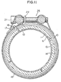
- Figure 1 is a fragmentary perspective view of the pipe joint according to the present invention;
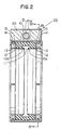
- Figure 2 is a cross-sectional view of the pipe joint taken lines A-A of Figure 3, embodying a novel features of present invention;
- Figure 3 is a right side view showing the pipe joint illustrated in Figure 2;
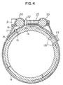
- Figure 4 is a cross-sectional view of parts of the pipe joint taken along line IV-IV shown in Figure 2;
- Figure 5 is a partly sectional fragmentary perspective view of the pipe joint showing the position of enlargement of inside diameter of holding ring, and enlargement of a circumference clearance between holding ring segments provided may be used with a ring expander;
- Figure 6 is a perspective view of clearance setting member of present invention;
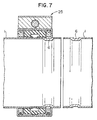
- Figure 7 is a cross-sectional view of the pipe joint illustrated in Figure 2 showing the position of the pipe joint as one side of the separated pipe is initially inserted into the pipe joint;
- Figure 8 is a cross-sectional view of the pipe joint illustrated in FIG. 2 showing the position of the pipe joint in moved positions to seal against the outside of the separated pipes and before being tightened down to seal against the outside of the separated pipes;
- Figure 9 is a cross-sectional view of the pipe joint illustrated in Figure 2 showing the position of the pipe joint in engaged position to engage against the groove of the separated pipes, and before being tightened down to seal against the outside of the separated pipes;
- Figure 10 is a cross-sectional view taken along lines X-X of Figure 9;
- Figure 11 is a cross-sectional view taken along lines XI-XI of Figure 9;
- Figure 12 is a cross-sectional view of the pipe joint illustrated in Figure 2 showing the position of the pipe joint in sealed position to seal against the outside of the separated pipe and being tightened down to seal against the outside of the separated pipes;
- Figure 13 is a side view taken along lines XIII of Figure 14 according to prior art;
- Figure 14 is a partial cross-sectional view of a pipe joint according to prior art;
- Figure 15A is a partial cross-sectional view of a pipe joint showing a groove at each end surface of separated pipe according to prior art; and
- Figure 15B is a partial cross-sectional view of a pipe joint showing a seal ring according to prior art.
-
- Preferred embodiments of a joint for pipes will be described in full detail in conjunction with the accompanying drawings.
- As shown in the drawings for purposes of illustration, the present invention is embodied in the pipe joint particularly adapted for use in connecting a separated pipes such as may be used in water supply system.
- The general arrangement in the fragmentary view of the pipe joint indicated generally at 25 in Figure 1.
- As shown in Figures 1-4, the
pipe joint 25 comprises acircumferential seal ring 10 having oppositeend holding ring 13 which adapted for sealing and connection to the separated pipes respectively.
Theseal ring 10 is generally C-shaped in cross section and provide alip portion seal ring 10 has a diameter of its inner circumference that is a slight larger dimensions than an outside diameter of the separated pipe. Theseal ring 10 has aconvex portion 10a on its outer circumference which act as a compression transmission part for the diameter reducing of theseal ring 10. - To seal the separated pipes within the
pipe joint 25, theseal ring 10 with theconvex portion 10a is compressed inward to be embedded and sealed into the outer surface of the separated pipe. - Each
slide washer 12 is rests between theseal ring 10 and theholding ring 13. Outside diameter of theslide washer 12 is slightly small dimension than outside diameter of theseal ring 10 and theholding ring 13, and inside diameter thereof is same dimension of inside diameter of theseal ring 10 and theholding ring 13. - This
slide washer 12 allows smooth radial relative sliding between theseal ring 10 and theholding ring 13. - Each
holding ring 13 is pluralized into quarter segment on circumference with the gap defined between each segment thereof, and provided with U-shapedouter groove 14 on their outer circumferences. The surface of thegroove 14 is provided with aring spring 15 in form of C-shaped to compress inwardly each quarter segment of theholding ring 13. One end of thering spring 15 has a turned upportion 16 for a insertion into ahole 17 of aholding housing 19. - Herein, the quarter segment is together in unity with the
holding ring 13. - Pin hole 18a having a depth are provided with the
holding ring 13 at side face of each two quarter segment, upper half quarter segment of theholding ring 13, includes a pair of oppositely arranged, and at adjacent to the center position thereof for insertion and removal of theexpander 18 as shown in Figure 5. - A
holding housing 19 having band body 19a is generally flat channel shaped in cross section, surrounds theseal ring 10 and theholding ring opening portion 19b between both end of the band body 19a. The end portion of the band body 19a is formed with afix loop 19c that is bent turn outwards in a curve along a web section thereof which fix arod member 20 within thefix loop 19c, respectively integral. - Each of
rod member locking bolt 21 having thread is threaded into the opposite thread openings ofrod member locking bolt 21 provide with aspacer portion 22 at the center position thereof to allow a secure locking of theholding housing 19 by threading of thelocking bolt 21 until thespacer portion 22. - In use, firstly, the
locking bolt 21 of thepipe joint 25 is sufficiently loosen to allowed diameter enlargement of theholding housing 19, accompanied with theholding ring pipe joint 25 is operative to permit easy insert and connection of the separated pipe 1, 1. - As shown in Figure 5, the
ring expander 18 is a tool alike a punch consisting of a pair of levers, a turn down portion are provided at one end thereof, and a handle portion at opposite end thereof. - As already mentioned above, in use, the turn down portion of the
ring expander 18 are inserted into thepin hole 13a of theholding ring 13, and circumference clearance between adjacent segments of theholding ring 13, are enlarged manually as shown in arrow with the handle portion of used ring expander 18, thus allowed the diameter enlargement of theholding ring 13 against compress force of thering spring 15. - In Figure 6, the
numeral 23 indicates an enlargement setting member for enlarged diameter setting of theholding ring 13, and may desirable be formed of flexible hard rubber. - A diameter enlargement of the holding
ring 13 by thering expander 18 produces the enlarged circumference clearance between adjacent segments of the holdingring 13, and the settingmember 23 is inserted thereto, which is maintained the diameter enlargement of the holdingring 13 after removal of thering expander 18. The settingmember 23 is in form of varied C-shaped. - The setting
member 23 provide the flat plate portion 23a,end portion 23b and pair ofspacing hook portion 23c on the opposite side of the flat plate portion 23a. The width of the settingmember 23 being approximately equal to the enlarged clearance between adjacent segments of the holdingring 13. - According to the preferred embodiments of present invention, the setting
member 23 is adapted to be partially wrapped around the holdinghousing 19, and pair ofspacing hook 23c is inserted into the enlarged circumference clearance between the segments of the holdingring 13. - As a result, the enlargement of the space defined between the inside diameter of the holding
ring - The setting
member 23 may be manually removed from the holdinghousing 19 accompanied with the holdingring pipe joint 25 of Figure 8 which is explain hereinafter. - As shown in Figure 6, the flat plate portion 23a of the setting
member 23 may be manually bend upwardly at bothend portion 23b of the flat plate portion 23a as direction of the arrow, and themember 23 may be quickly removed from the holdinghousing 19. - When diameter enlargement of the holding
ring bolt 21 tightened within the thread openings of therod members bolt 21 to be threadably tightened onto the holdinghousing 19. - As already mentioned above, the turned up
portion 16 of thering spring 15 inserted into thehole 17 of the holdinghousing 19, and the quarter segment with U-shapedouter groove 14 that compressed inwardly with thering spring 15 are together in unity with the holdingring 13. Therefore, the holdingring 13 may be keep correctly in the specified position within the holdinghousing 19, and eliminate swell out outwardly from inside of the holdinghousing 19 to the axis of separated pipe. Additionally, a circumference rotation of thering spring 15 itself around the holdingring 13 be eliminated. - The opening portion of the
ring spring 15 in form of C-shaped may be in the specified position within the holdinghousing 19, and allowed that the segment of the holdingring 13 may be in the specified position that the settingmember 23 may be inserted thereto so that in effect a insertion of the settingmember 23 is at ease of operation. - As shown in Figure 7 the pipe joint 25 illustrated in Figure 1 is initially inserted into the outer surface of the one side of the separated pipe 1, and one of the holding
ring 13 of the pipe joint 25 is located facing to thegroove 6 at end of the outer surface of the separated pipe 1. Under this initial position, as previously described, the pipe joint 25 is moved to permit smoothly inserted into the outer surface of one side of the separated pipe 1. - As shown in Figure 8, the pipe joint 25 illustrated in Figure 1 is in moved position that moved from the initial position thereof as illustrated in Figure 7, to the outer surface of the other side of the separated pipe 1, and is inserted into the outer surfaces of the both side of the separated pipe 1, 1 and the position of each of the holding
ring grooves member 23 is removed from the holdinghousing 19.
As a result, the reduction of the space defined as previously described, the inside surface of each of the holdingring groove - As shown in Figure 9, the pipe joint 25 illustrated in FIG. 1 is in engaged position that each of the holding
ring groove - Referring to Figures 10 and 11 the pipe joint 25 is in the engaged position that will be seen by referring to Figure 9.
- As shown in Figure 12, the pipe joint 25 is finally in sealed position being tightened down to that is the normal operating condition. Each of the holding
ring groove housing 19 is tightened by threading of the lockingbolt 21 until thespacer portion 25 into the opposite opening of therod member ring groove - For sealing against the outside of the separated pipe 1, 1 within the pipe joint 25, the
convex portion 10a of theseal ring 10 is pushed radially inwardly to squeeze theseal ring 10 that together surround the opening between both end of the separated pipe 1, 1 and thelip portion ring 10 embedded within outside surface of both end of the separated pipe 1, 1, thereby, eventually making the pipe joint for connecting the separated pipes together, and used for a leakage proof fluid flow in the water or other fluid supply system. - As an added feature, however, the holding
ring groove - In regard to assemble the pipe joint 25, an incorrect inserting or lack of the tightening of the holding
housing 19 may be cause water leakage from the pipe joint 25. - Further, regardless of the tightening of the holding
housing 19 into the separate pipe is provided, if nothing is placed in engagement of the holdingring groove - Thus, it is seen from the foregoing that present invention brings to the art a unique substantially pipe joint 25 which is particularly adapted for easily connecting the separated pipe 1 and 1 in a water supply system.
- Advantageously, this is achieved in the exemplary embodiment through the use of the holding ring which is comprised of the uniquely shaped divided segments thereof which enable use of the ring spring for complete tightening to engage within the groove and against separation from the separated pipes, further, the ring spring be eliminate swell out of the holding ring from inside of the holding housing, and eliminate circumference rotation by itself.
- Furthermore, the ring expander in the exemplary embodiment is an advantageous feature that is capable of fitting into the pin hole of the holding ring that create enlargement of circumference clearance between adjacent segment of the holding ring, thus, allowed the diameter enlargement of the holding
ring 13 against compress force of thering spring 15. - The setting member in the exemplary embodiment is an advantageous feature that is capable of maintaing the diameter enlargement of the holding ring after removal of the ring expander, and is at ease of prior to installing operation of the pipe joint.
- Further, the embodiment of the pipe joint has the advantage of additional simplicity and expense of the pipe joint disconnection from the separated pipes. The pipe joint disconnection from the separated pipes is allowed in contrast with connecting the separated pipes together.
- In the case of the pipe joint disconnection as required, the locking
bolt 21 of the pipe joint is sufficiently loosen to allow diameter enlargement of the holdinghousing 19, thering expander 18 allowed the enlargement of circumference clealance between adjacent segments of the holdingring member 23 is inserted into above circumference clearance, thus, the enlargement of the space defined between the inside diameter of the holdingring - Of additional advantage is that the present invention enables easily recognizing the correct alignment of the pipe joint, thereby eventually making the pipe joint itself superflows as fluid leakage without operator awareness would be prevented.
Claims (6)
- A pipe joint (25) having a holding housing (19) with two end portions and a flow passage extending therebetween along a central axis of the housing (19) with both of the end portions being adapted for tightening connection and independent compressing sealingly against the outside of separated pipes (1,1) inserted therein, comprising;the holding housing (19) having a band body (19a) surrounding a seal ring (10) and a holding ring(13),the band body (19a) being formed on both ends with a loop (19c) bent outwards in a curve to fix two rod members (20), where at the top portion of the band body (19a), a locking bolt (21) is threaded into the opposite thread opening of the rod members (20) for tightening the holding housing (19);the seal ring (10) having a lip portion (10b) for sealing against the outside of the separated pipes (1,1), and having a diameter of its inner circumference which is of a slight larger dimension than the outside diameter of the separated pipes (1,1);the holding ring (13) mounted beside the seal ring (10), including four quarter segments on a circumference which is together in unity with itself by compress force of a ring spring (15) encircling each of the quarter segments, being tightened down to engage into a groove (6) of the outside of the separated pipes (1,1), and a turned up portion (16) of the ring spring (15) being inserted into a hole (17) adjacent to the top portion of -the band body (19a) of the holding housing (19); anda ring expander (18) being provided removably for enlargement of circumference clearance between adjacent segments of the holding ring (13).
- The pipe joint (25) as set forth in Claim 1, in which the pipe joint (25) has an enlargement setting member (23) capable of partially wrapping around the holding housing (19) for maintaining the diameter enlargement of the holding ring (13) after removal of the ring expander (18).
- The pipe joint (25) as set forth in Claim 1, in which the ring expander (18) is alike a punch consisting of a pair of levers, a turn down portion is provided at one end thereof, and the handle portion at an opposite end thereof, and the turn down portion is inserted into two pin holes (13) of the holding ring (13).
- The pipe joint (25) as set forth in Claim 1, in which the pipe joint (25) has an circumferentially extending groove (14) formed at the outside surface of each of the quarter segments of the holding ring (13), the ring spring (15) encircles each of the quarter segments and is seated within the groove (14) to hold each of the quarter segment together in unity.
- The pipe joint (25) as set forth in Claim 1, in which the seal ring (10) being generally C-shaped in cross section, formed of a rubber having the property of gasket material, and having a convex portion (10a) on its outer circumference acts as a compression transmission part for reducing the inside diameter of the seal ring (10).
- The pipe joint (25) as set forth in Claim 1, in which the holding housing (19), has a slide washer (12) being rest between the seal ring (10) and the holding ring (13), to allow a radial relative sliding between the seal ring (10) and the holding ring (13).
Applications Claiming Priority (3)
| Application Number | Priority Date | Filing Date | Title |
|---|---|---|---|
| JP26071395 | 1995-09-13 | ||
| JP260713/95 | 1995-09-13 | ||
| JP26071395A JP3151551B2 (en) | 1995-09-13 | 1995-09-13 | Pipe fittings |
Publications (2)
| Publication Number | Publication Date |
|---|---|
| EP0763688A1 EP0763688A1 (en) | 1997-03-19 |
| EP0763688B1 true EP0763688B1 (en) | 2001-08-01 |
Family
ID=17351731
Family Applications (1)
| Application Number | Title | Priority Date | Filing Date |
|---|---|---|---|
| EP96113348A Expired - Lifetime EP0763688B1 (en) | 1995-09-13 | 1996-08-20 | Pipe joint |
Country Status (8)
| Country | Link |
|---|---|
| US (1) | US5722695A (en) |
| EP (1) | EP0763688B1 (en) |
| JP (1) | JP3151551B2 (en) |
| KR (1) | KR100256769B1 (en) |
| CN (1) | CN1062061C (en) |
| DE (1) | DE69614207T2 (en) |
| HK (1) | HK1002366A1 (en) |
| TW (1) | TW311166B (en) |
Families Citing this family (22)
| Publication number | Priority date | Publication date | Assignee | Title |
|---|---|---|---|---|
| US20050082831A1 (en) * | 2003-10-15 | 2005-04-21 | Borland Robin N. | Conduit coupling |
| DE102004050843B4 (en) * | 2004-10-18 | 2010-01-07 | Linder, Hermann J. | Device and activator arrangement for conveying solids in a pipeline, and method therefor |
| DE202004017501U1 (en) * | 2004-11-11 | 2005-01-05 | Kirchhoff Gmbh & Co.Kg | Device for connecting two exhaust pipes leading off |
| JP4699150B2 (en) * | 2005-09-16 | 2011-06-08 | 日本ヴィクトリック株式会社 | Housing type pipe fitting |
| US20110109081A1 (en) * | 2009-11-10 | 2011-05-12 | Benton Frederick Baugh | Drilling riser connector |
| CN101847917B (en) | 2010-03-29 | 2011-12-21 | 燕山大学 | Axially-rotating equal-width curve double-stator multi-speed motor |
| JP5886677B2 (en) * | 2011-06-17 | 2016-03-16 | 山本 和正 | Fasteners, couplings, and fences |
| CN102322552A (en) * | 2011-08-26 | 2012-01-18 | 华恩夫成套设备(上海)有限公司 | Heavy-caliber O-shaped pipeline locking device |
| CN102364194A (en) * | 2011-09-30 | 2012-02-29 | 苏州捷英特管道技术有限公司 | Food-grade pipe joint |
| KR101366169B1 (en) * | 2012-04-23 | 2014-02-24 | 장경근 | Hose clamping device |
| KR101233409B1 (en) * | 2012-09-28 | 2013-02-15 | 천영민 | Expanded pipe and pipe joint |
| EP3048353B1 (en) * | 2015-01-26 | 2018-12-26 | Straub Werke AG | Pipe coupling for connecting two pipe ends or pipe clamps for sealing a defective pipe |
| CN107044570A (en) * | 2017-06-14 | 2017-08-15 | 苏州斯派克思精密机械有限公司 | A kind of portable locking device |
| CN108443611B (en) * | 2018-03-15 | 2019-05-28 | 安徽江淮汽车集团股份有限公司 | A kind of flexible collar assembly |
| CN112648470B (en) * | 2019-10-11 | 2022-11-04 | 中国石油天然气股份有限公司 | Pipeline repairing device |
| USD980391S1 (en) | 2019-10-28 | 2023-03-07 | Zurn Industries, Llc | Valve tamper shield |
| CN112780867B (en) * | 2019-11-11 | 2022-11-04 | 安徽汇久管业有限公司 | PPR water pipe joint |
| CN111946690B (en) * | 2020-08-14 | 2022-05-03 | 安徽肥地肥业有限责任公司 | Constant-speed hydraulic driving device |
| US11725464B2 (en) * | 2021-07-28 | 2023-08-15 | Benton Frederick Baugh | Drilling riser connector |
| CN113732958A (en) * | 2021-09-01 | 2021-12-03 | 沪东中华造船(集团)有限公司 | Segmented pre-assembled pipe seal cleaning and protecting device and using method thereof |
| CN114215315B (en) * | 2021-12-17 | 2023-04-25 | 宿令雁 | Construction device for outer wall decoration surface for building construction and use method |
| CN115013627B (en) * | 2022-06-08 | 2023-08-08 | 合肥海博工程设计集团有限公司 | Old pipeline joint leakage-proof equipment for community transformation |
Family Cites Families (11)
| Publication number | Priority date | Publication date | Assignee | Title |
|---|---|---|---|---|
| US944877A (en) * | 1909-06-08 | 1909-12-28 | Ernest August Koschinski | Coupling. |
| US3405957A (en) * | 1967-04-03 | 1968-10-15 | Richard O. Chakroff | Flexible tube coupling |
| BE789346A (en) * | 1971-10-01 | 1973-01-15 | Victaulic Co Of America | PIPE ASSEMBLY SYSTEM BY MEANS OF STUDS AND FITTINGS FOR THEM |
| US4150847A (en) * | 1976-06-04 | 1979-04-24 | Cenzo Herbert A De | Flexible tube coupling with symmetrical anchor ring |
| AT348838B (en) * | 1976-07-21 | 1979-03-12 | Straub Immanuel | PIPE COUPLING |
| US4662656A (en) * | 1983-09-09 | 1987-05-05 | Foster-Miller, Inc. | Pipeline coupling |
| DE3501583C3 (en) * | 1985-01-18 | 1995-02-09 | Bruno Appel Kg | Device for the axial connection of two sleeveless pipes |
| US4822077A (en) * | 1988-09-26 | 1989-04-18 | Urdan Industries (Usa) Inc. | Pipe coupling reducing insert |
| NZ238986A (en) * | 1990-07-27 | 1997-01-29 | Taylor Kerr Couplings Ltd | Fliud-tight pipe coupling with slots in sealing sleeve that receive teeth of gripping ring |
| DE59203992D1 (en) * | 1992-01-16 | 1995-11-16 | Straub Federnfabrik | Pipe coupling. |
| NL9401411A (en) * | 1994-08-31 | 1996-04-01 | Fischer Georg Waga Nv | Tube coupling. |
-
1995
- 1995-09-13 JP JP26071395A patent/JP3151551B2/en not_active Expired - Fee Related
-
1996
- 1996-04-06 TW TW085104030A patent/TW311166B/zh active
- 1996-08-19 US US08/699,252 patent/US5722695A/en not_active Expired - Fee Related
- 1996-08-20 DE DE69614207T patent/DE69614207T2/en not_active Expired - Fee Related
- 1996-08-20 EP EP96113348A patent/EP0763688B1/en not_active Expired - Lifetime
- 1996-08-24 KR KR1019960035264A patent/KR100256769B1/en not_active IP Right Cessation
- 1996-09-13 CN CN96122704A patent/CN1062061C/en not_active Expired - Fee Related
-
1998
- 1998-02-04 HK HK98100829A patent/HK1002366A1/en not_active IP Right Cessation
Also Published As
| Publication number | Publication date |
|---|---|
| JP3151551B2 (en) | 2001-04-03 |
| DE69614207T2 (en) | 2001-11-15 |
| CN1159528A (en) | 1997-09-17 |
| HK1002366A1 (en) | 1998-08-21 |
| TW311166B (en) | 1997-07-21 |
| EP0763688A1 (en) | 1997-03-19 |
| KR970016254A (en) | 1997-04-28 |
| DE69614207D1 (en) | 2001-09-06 |
| CN1062061C (en) | 2001-02-14 |
| KR100256769B1 (en) | 2000-05-15 |
| JPH0979450A (en) | 1997-03-25 |
| US5722695A (en) | 1998-03-03 |
Similar Documents
| Publication | Publication Date | Title |
|---|---|---|
| EP0763688B1 (en) | Pipe joint | |
| US5658021A (en) | Pipe joint | |
| US6099045A (en) | Fitting for the connection of pipes by means of pressing | |
| US4111234A (en) | Repair device for pipes | |
| EP0945661B1 (en) | Device for connecting a pipe joint | |
| US5476292A (en) | Pipe couplings | |
| US4073513A (en) | Pipe branch fitting | |
| US5230537A (en) | Pipe coupling | |
| US6412824B2 (en) | Pipe branch fitting | |
| GB2097501A (en) | Pipe coupling with gasket locating means | |
| US5769467A (en) | Pipe couplings for misaligned or out-of-round pipes and expanding/contracting pipes | |
| US5207459A (en) | Transition coupling for pipes | |
| US6641178B2 (en) | Jointing system for pipes | |
| US5111879A (en) | Sanitary locking lip split well seal | |
| EP0309457B1 (en) | Coupling for coupling tubular members | |
| US6000729A (en) | Hose coupling | |
| JP3638617B2 (en) | Improved band with slotted wedge cam | |
| JP4102468B2 (en) | Pipe connection device | |
| KR100432656B1 (en) | Pipe coupling device | |
| US20030080563A1 (en) | Irrigation valve | |
| EP0709612B1 (en) | Pipe couplings | |
| JP4140873B2 (en) | Tube fixing device | |
| JPS5813180Y2 (en) | Valve with expansion joint | |
| US20230383876A1 (en) | Compression fitting | |
| US20230167929A1 (en) | Pipe coupling gasket assembly |
Legal Events
| Date | Code | Title | Description |
|---|---|---|---|
| PUAI | Public reference made under article 153(3) epc to a published international application that has entered the european phase |
Free format text: ORIGINAL CODE: 0009012 |
|
| AK | Designated contracting states |
Kind code of ref document: A1 Designated state(s): DE GB |
|
| 17P | Request for examination filed |
Effective date: 19970619 |
|
| 17Q | First examination report despatched |
Effective date: 20000204 |
|
| GRAG | Despatch of communication of intention to grant |
Free format text: ORIGINAL CODE: EPIDOS AGRA |
|
| GRAG | Despatch of communication of intention to grant |
Free format text: ORIGINAL CODE: EPIDOS AGRA |
|
| GRAH | Despatch of communication of intention to grant a patent |
Free format text: ORIGINAL CODE: EPIDOS IGRA |
|
| GRAH | Despatch of communication of intention to grant a patent |
Free format text: ORIGINAL CODE: EPIDOS IGRA |
|
| GRAA | (expected) grant |
Free format text: ORIGINAL CODE: 0009210 |
|
| AK | Designated contracting states |
Kind code of ref document: B1 Designated state(s): DE GB |
|
| PGFP | Annual fee paid to national office [announced via postgrant information from national office to epo] |
Ref country code: GB Payment date: 20010807 Year of fee payment: 6 |
|
| REF | Corresponds to: |
Ref document number: 69614207 Country of ref document: DE Date of ref document: 20010906 |
|
| PGFP | Annual fee paid to national office [announced via postgrant information from national office to epo] |
Ref country code: DE Payment date: 20011023 Year of fee payment: 6 |
|
| REG | Reference to a national code |
Ref country code: GB Ref legal event code: IF02 |
|
| PLBE | No opposition filed within time limit |
Free format text: ORIGINAL CODE: 0009261 |
|
| STAA | Information on the status of an ep patent application or granted ep patent |
Free format text: STATUS: NO OPPOSITION FILED WITHIN TIME LIMIT |
|
| 26N | No opposition filed | ||
| PG25 | Lapsed in a contracting state [announced via postgrant information from national office to epo] |
Ref country code: GB Free format text: LAPSE BECAUSE OF NON-PAYMENT OF DUE FEES Effective date: 20020820 |
|
| PG25 | Lapsed in a contracting state [announced via postgrant information from national office to epo] |
Ref country code: DE Free format text: LAPSE BECAUSE OF NON-PAYMENT OF DUE FEES Effective date: 20030301 |
|
| GBPC | Gb: european patent ceased through non-payment of renewal fee |
Effective date: 20020820 |