EP0762826B1 - Identity and cow estrus indicator - Google Patents
Identity and cow estrus indicator Download PDFInfo
- Publication number
- EP0762826B1 EP0762826B1 EP95922042A EP95922042A EP0762826B1 EP 0762826 B1 EP0762826 B1 EP 0762826B1 EP 95922042 A EP95922042 A EP 95922042A EP 95922042 A EP95922042 A EP 95922042A EP 0762826 B1 EP0762826 B1 EP 0762826B1
- Authority
- EP
- European Patent Office
- Prior art keywords
- transmitting
- unit
- data
- detector
- antenna
- Prior art date
- Legal status (The legal status is an assumption and is not a legal conclusion. Google has not performed a legal analysis and makes no representation as to the accuracy of the status listed.)
- Expired - Lifetime
Links
Images

Classifications
-
- A—HUMAN NECESSITIES
- A61—MEDICAL OR VETERINARY SCIENCE; HYGIENE
- A61B—DIAGNOSIS; SURGERY; IDENTIFICATION
- A61B10/00—Other methods or instruments for diagnosis, e.g. instruments for taking a cell sample, for biopsy, for vaccination diagnosis; Sex determination; Ovulation-period determination; Throat striking implements
- A61B10/0012—Ovulation-period determination
-
- A—HUMAN NECESSITIES
- A01—AGRICULTURE; FORESTRY; ANIMAL HUSBANDRY; HUNTING; TRAPPING; FISHING
- A01K—ANIMAL HUSBANDRY; CARE OF BIRDS, FISHES, INSECTS; FISHING; REARING OR BREEDING ANIMALS, NOT OTHERWISE PROVIDED FOR; NEW BREEDS OF ANIMALS
- A01K11/00—Marking of animals
- A01K11/006—Automatic identification systems for animals, e.g. electronic devices, transponders for animals
-
- A—HUMAN NECESSITIES
- A61—MEDICAL OR VETERINARY SCIENCE; HYGIENE
- A61D—VETERINARY INSTRUMENTS, IMPLEMENTS, TOOLS, OR METHODS
- A61D17/00—Devices for indicating trouble during labour of animals ; Methods or instruments for detecting pregnancy-related states of animals
- A61D17/002—Devices for indicating trouble during labour of animals ; Methods or instruments for detecting pregnancy-related states of animals for detecting period of heat of animals, i.e. for detecting oestrus
Definitions
- the present invention relates to a movable device for auto-matic indication both of identity and of other variables, the device being in particular intended to be carried by a domestic animal such as a cow.
- Identification systems for domestic animals which comprise a passive transponder unit attached to the animal are well-known, see e.g. the patent US-A 4,510,495.
- the transponder unit receiver circuits are provided for receiving radio waves of high frequency and for storing energy drawn from these waves. Further there are transmitter circuits for trans-mitting, by means of such stored energy and by radio waves, identity information which uniquely identifies the transmitting unit and thereby the domestic animal to which the transponder unit is attached.
- identity information which uniquely identifies the transmitting unit and thereby the domestic animal to which the transponder unit is attached.
- such a transponder circuit which in responding to a high frequency radio signal issues an identification code using the energy of the received signal or, as an alternative, energy from a battery.
- a domestic animal such as a dairy cow is provided with a transponder unit which is connected to an electronic counter register powered by a battery for storing the number of signals obtained from a motion detector or sensor.
- the transponder unit transmits data by means of radio signals data, this data comprising information which constitutes an identification number of the domestic animal and also indicates the number of movements that the domestic animal has made. By evaluating this latter transmitted number it is possible to decide whether the cow is or is not in the estrus period.
- a transponder unit having a motion sensor and a counter for the number of movements is also disclosed in the patent US-A 4,618,861 for John W. Gettens et al., where the supply of electrical current instead is provided by the way that the motion sensor in the conventional way generates electrical pulses and by storing and utilizing the energy of the pulses for the transmission of information.
- an estrous detection system using an implanted detector determining the estrous of an animal by evaluating the force applied during sustained mounting by another animal. When the number of mountings within a fixed period exceeds a threshold a signal is emitted from the system using the energy of a battery.
- the transmitters of different animals can be tuned to different frequencies to achieve differentiation between different animals or information can be encoded in each transmitter emission pulse indicating the transmitter producing the signal.
- a battery has a limited useful lifetime, which is a distinctive disadvantage for identification units, which in the ideal case are to be attached to the animal and are to remain there and be operative for a long time period.
- the motion sensor see the mentioned patent for John W. Gettens, can itself, having no current supply from the outside, generate the pulses which are used for modifying a register or a memory.
- a conventional passive transponder unit is arranged which is connected to an antenna.
- the transponder comprises means for storing electrical energy from electrical voltage pulses received on the antenna and can by means of the stored energy transmit on the antenna pulse sequences carrying information such as identification data of the device.
- a permanent electrical current source is provided such as a lithium battery, which drives a processor.
- the processor receives signals from a motion sensor and is coupled to a transmitter having an antenna and can activate the transmitter for transmitting radio signals having a good range, when the motion sensor signals an increased activity, such as for a non-milking cow during the estrus period.
- a first passive subunit or transponder unit comprising a receiver antenna and means for storing electrical energy comprised in electrical voltage pulses received on the receiver antenna and further comprising a first transmitter antenna and means for transmitting on the transmitter antenna pulse sequences containing information.
- a second subdevice is arranged, comprising an electrical current source of battery type and a second transmitter antenna and means for transmitting pulse sequences containing information on this second transmitter antenna.
- the second subdevice comprises suitably a processor having memory means for storing data, in particular changing data obtained from a detector or sensor.
- the processor will signal an abnormal state when the changing data have changed sufficiently quickly, such as that the data is a counter value indicating the number of detected movements, the processor signalling when the value has increased beyond a pre-determined threshold value during a set time, or generally has passed the threshold value in a predetermined direction.
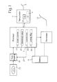
- a device in a block diagram and partly schematically, a device is illustrated intended to be placed in a casing or house, see Fig. 2, which in turn is intended to be for instance suspended around the neck of a domestic animal.
- the device comprises functions for identification and detection of movements.
- a transponder unit 1 is used of principally conventional type, such as a unit which is sold by the company Texas Instruments under the trade name "TIRIS", see also for instance the patent documents DE-C2 3920666, DE-C1 4002801, EP-A1 0480530, EP-A1 0301127, DE-C1 4004196, EP-B1 0299557, US-A 5,510,495, and US A 5,028,918, and it will not be described here in detail.
- the transponder 1 comprises an antenna 3 and is susceptible of receiving thereon high frequency energy (frequencies of for instance about 100 - 200 kHz), which is used for driving circuits in the transponder, primarily for transmitting identification data stored in a register, as is illustrated at 5 in Fig. 1.
- high frequency energy frequencies of for instance about 100 - 200 kHz
- the processor is designed for normal electronic processor operations and is provided with memories, clock circuits, etc.
- the processor 7 has an exterior own constant electrical current supply in the shape of a suitable electrochemical battery such as a lithium battery 9.
- the battery 9 also supplies power to a transmitter 11 of radio frequency waves, for instance having a frequency in the range of about 30 MHz, and is therefor connected to an antenna 13.
- the processor 7 receives as an input signal electrical pulses on a line from a motion sensor 15, which preferably is of the type, which is described in the patent US-A 5,183,056 for Björn Dalén et al, assigned to Siemens Elema AB.
- the electrical pulses from the detector 15 can be shaped to suitable electrical voltage pulses by a pulse forming circuit 14, before they are delivered to the processor.
- the processor 7 can also receive signals from the transponder unit 1 and can possibly therethrough also transmit data information by means of the antenna 3 connected to the transponder 1.
- the device illustrated in fig. 1 operates in the following way.
- the motion sensor 11 detects all the time or permanently the movement of for instance a domestic animal, to which the device is attached in some way as being suspended in a neck chain, and electrical signals indicating the movements are sent to the microprocessor 7.
- the microprocessor 7 is in the preferred case active only during periodically repeated time intervals such as during some minute in each hour but can also possibly be permanently active and the energy supply to the processor 7 is always provided, during the active time periods thereof, from the battery 9.
- the pulses received from the movement sensor 15 are evaluated and counted, the result being stored in a register as a pulse counter 17.
- the processor 7 contains, as has been indicated above, also a clock circuit and it is arranged to store the present time in a register illustrated at 19. By means of the values in these registers, i.e. the number of pulses in the pulse counter 17 and the current time in the register 19, the processor 7 evaluates at each instant when it is active, whether the movement activity or intensity, i.e. the number of movements per time unit, is larger than a threshold value stored in a third register 21. If the movement intensity is sufficiently high, the processor 7 activates the transmitter 11, which is also powered by the battery 9, and transmits a message on the antenna, the message containing both identifying information accessed from the memory of the transponder unit 1, and information signalling that the movement intensity now is larger than the threshold value. Further, a flag in a register 22 is set indicating that the movement intensity is now high. By the battery operation of the transmitter 11 the signal issued from the antenna 13 will obtain a reasonably large transmission range, for instance of the magnitude of order of hundreds of metres.
- the whole device instead approaches a specially arranged questioning station, not shown, which for domestic animals can be located at the entrance of a feeding place and which issues pulses of a frequency of the magnitude of order 100 - 200 kHz, and when the device is sufficiently close to the questioning station, for instance 50 cm at most from the antenna thereof, the electrical energy of the radio waves can be received by the transponder unit 1 by means of its associated antenna 3.
- the transponder antenna 3 operates in a similar manner as the secondary winding in a transformer, and the received energy or induced energy is stored in a suitable way, for instance in a capacitor, indicated at 23.
- the energy stored is used by the transponder unit 1 for then transmitting on its antenna 3 identifying information and also a data value accessed from the activity flag in the register 22 in the processor 7 indicating whether the movement intensity at the latest measurement has exceeded or was lower than the threshold value, which is stored in the register 21 in the processor 7.
- the radio signals of a higher frequency issued from the antenna 13 are also received by a receiver unit, not shown, for instance the same questioning station which has been already described, and are evaluated in a suitable way as well as the mentioned data value transmitted by the transponder unit 1.
- a receiver unit not shown, for instance the same questioning station which has been already described, and are evaluated in a suitable way as well as the mentioned data value transmitted by the transponder unit 1.
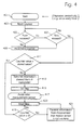
- Fig. 4 an example of a flow diagram is illustrated comprising the various operational steps performed by the processor.
- the procedure for measuring movement activity is to be started, by activating the processor 7, for instance by some suitable timing circuit, not shown, therein.
- the procedure then starts in a start block 401, after which the counter 17 is reset to zero in a block 403.
- the counter 17 is incremented in a block 409, after which the procedure continues to the block 407 for deciding again whether the time of the measurement has elapsed. If it is decided in the block 407 that the time has elapsed, it is determined in a block 411, whether the value of the counter is larger than the threshold value stored in the register 21. If it is true, in a block 413 the transmitter 11 is started for transmitting information that the activity is now high for the animal in question. After that the flag stored in the register 22 is set in a block 415, and then the procedure is ended in a block 417 for awaiting a new measuring period.
- the procedure continues to a block 419. Therein it is decided whether any pulses at all has been counted in the procedure, i.e. if the counter in the register 17 still is equal to zero. If it is the case, the movement detector is very probably faulty and then the procedure continues to a block 421, where the rf-transmitter 11 is activated for transmitting information that the motion detector of the domestic animal probably is faulty and needs to be replaced. Then in a block 423 the flag stored in the register 22 is reset, after which the procedure is ended in the block 417.
- FIG. 2 the circuits of Fig. 1 are illustrated as built into a casing or house 25, comprising holes or openings 27 for attachment to a neck chain, neck belt or similar device (not shown) of a domestic animal.
- a circuit board 29 is mounted in the house 25 and comprises the circuits illustrated in Fig. 1 connected by conductive paths, not shown, on the board 25.
- the antenna 3 is arranged in the shape of a winding having several turns located directly inside the circumference of the house 25 and is through electrically conducting wires 31 connected to electrically conducting areas of the board 25.
- the antenna 13 for radio frequency comprises a shorter electrical conducting wire also connected to a suitable conducting area on the board 25.
- FIG. 3 A simple embodiment of the pulse shaping circuit 14 is illustrated in Fig. 3.
- the output signal from the motion detector 15 is supposed to be of type sinus signal having a somewhat varying frequency and a decreasing amplitude for each detected movement. It is provided to an operational amplifier 33 on one of its input terminals, for instance its inverting terminal, a reference voltage V ref . being applied to its other input terminal.
- the output signal from the operational amplifier will then have a shape comprising pulses of a suitable constant voltage level but having somewhat varying length or width.
- the pulses are evaluated in a suitable manner by the microprocessor 7, for instance by counting the number thereof.
- the reference voltage V ref The reference voltage V ref .
- the microprocessor can be controlled by the microprocessor through a DA-converter or similar device, not shown, built into it and thus the non-inverting input terminal of the operational amplifier 25 can be connected to the processor 7 through a line 27, shown in dotted lines in fig. 1.
- the transmitter 11 can alternatively be the transmitter part which is conventionally arranged in passive transponders, and in that case naturally the antenna 13 is the same as the antenna 3 for the transponder unit 1, i.e. the transmitter 11 and the antenna 13 are omitted and the battery 9 delivers, at the particular occasions described, energy for operation of the transponder unit 1.
Description
Claims (13)
- A method for monitoring a movable unit, in particular a domestic animal, the method comprising the steps of:characterized by the additional steps of:transmitting electro-magnetic pulses wirelessly from a fixed station, which pulses can be received by the movable unit, only when it is in the neighbourhood of the fixed station, andreceiving (1) wirelessly in the unit, when the unit is located in the neighbourhood of the fixedly arranged station, the electro-magnetic pulses transmitted by the station and storing (23) electrical energy comprised in the received electro-magnetic pulses, and transmitting (I) wirelessly from the unit, when the unit is still located in the neighbourhood of the fixedly arranged station, information in regard of the identity (5) of the unit using for the transmitting the electrical energy stored when receiving the electro-magnetic pulses,providing the movable unit with a sensor (15),detecting by the detector different states, at least a first normal state and a second special state, which can be taken by the movable unit, the states in particular being related to the movement intensity of the movable unit, andalways transmitting (11) wirelessly using energy drawn from a permanent electrical current source (9), in particular an electrochemical battery, when the sensor detects the second special state information both in regard of the identity of the unit and of the fact that the unit now takes the second state.
- A method according to claim 1, characterized in that in the step of receiving and transmitting wirelessly, when the unit is located in the neighbourhood of the fixedly arranged station, the receiving and transmitting is made through a transponder antenna (3) and that in the step of always transmitting wirelessly, when the sensor detects the second special state, the transmitting is made through an antenna (13) different from the transponder antenna.
- A method according to any of claims 1 - 2, characterized in that in the step of receiving and transmitting wirelessly, when the unit is located in the neighbourhood of the fixedly arranged station, also information is transmitted in regard of the state which the sensor has latest detected.
- A method according to any of claims 1 - 3, characterized in that in the step of receiving and transmitting wirelessly, when the unit is located in the neighbourhood of the fixedly arranged station, the transmitting is made directly after receiving the electro-magnetic pulses.
- A device according to any of claims 1 - 4, characterized in that in the step of detecting, data (17) obtained from the detector (15) and data (19) indicating the time of obtaining the data from the detector are stored.
- A device according to claim 5, characterized in that in the step of transmitting, when the sensor detects the second special state, the transmitting is made when a changing data value (17) stored in the memory means and obtained from the detector passes in a predetermined direction, in particular exceeds, a threshold value (21) also stored in the memory means.
- A device for transmitting data from a movable unit, in particular from a domestic animal, the device comprising a first passive subdevice comprisingcharacterized bya transponder antenna (3),storing means (23) connected to the transponder antenna for storing electrical energy comprised in electro-magnetic pulses received on the transponder antenna, andfirst transmitting means (1) connected to the transponder antenna and the storing means for transmitting on the transponder antenna pulse sequences containing information comprising identification data (5) in regard of the identity of the unit using for the transmitting the electrical energy stored in the storing means when receiving the electro-magnetic pulses,
a second subdevice comprisinga detector (15) for detecting different states, at least a first normal state and a second special state, which can be taken by the movable unit, the states in particular being related to the movement intensity of the movable unit,a permanent electrical current source (9), in particular an electrochemical battery, for supplying electrical current during a long time without recharging,a transmitter antenna (13), andsecond transmitting means (11) connected to the detector, the current source and the transmitter antenna for transmitting on the transmitter antenna pulse sequences, when the sensor detects the second special state, information both in regard of the identity of the unit and of the fact that the unit now takes the second state, using energy drawn from the permanent electrical current source. - A device according to claim 7, characterized by memory means (17, 19) comprised in the second subdevice for storing data obtained from the detector and data indicating the time of obtaining the data from the detector.
- A device according to claim 8, characterized by an evaluating unit (7) for evaluation of signals obtained from the detector and for storing in the memory means the result of this evaluation.
- A device according to any of claims 7 - 9, characterized in that the transponder antenna (3) is different from the transmitter antenna (13).
- A device according to any of claim 7 - 10, characterized in that the first transmitting means (1) are arranged to transmit in the pulse sequences also information obtained from the second subdevice in regard of the time when the unit has latest taken the second state.
- A device according to claim 8, characterized in that the the first transmitting means are arranged to transmit in the pulse sequences also information obtained from the memory means in the second subdevice in regard of the time when the unit has latest taken the second state.
- A device according to claim 8, characterized in that the second transmitting means are arranged to transmit when a changing data value (17) stored in the memory means passes in a predetermined direction, in particular exceeds, a threshold value (21) also stored in the memory means.
Applications Claiming Priority (3)
| Application Number | Priority Date | Filing Date | Title |
|---|---|---|---|
| SE9401890 | 1994-06-01 | ||
| SE9401890A SE504267C2 (en) | 1994-06-01 | 1994-06-01 | Identity and cobstone indicator |
| PCT/SE1995/000630 WO1995032616A1 (en) | 1994-06-01 | 1995-06-01 | Identity and cow estrus indicator |
Publications (2)
| Publication Number | Publication Date |
|---|---|
| EP0762826A1 EP0762826A1 (en) | 1997-03-19 |
| EP0762826B1 true EP0762826B1 (en) | 2002-04-03 |
Family
ID=20394204
Family Applications (1)
| Application Number | Title | Priority Date | Filing Date |
|---|---|---|---|
| EP95922042A Expired - Lifetime EP0762826B1 (en) | 1994-06-01 | 1995-06-01 | Identity and cow estrus indicator |
Country Status (7)
| Country | Link |
|---|---|
| US (2) | US5857434A (en) |
| EP (1) | EP0762826B1 (en) |
| JP (1) | JP3602132B2 (en) |
| AU (1) | AU2686795A (en) |
| DE (1) | DE69526223T2 (en) |
| SE (1) | SE504267C2 (en) |
| WO (1) | WO1995032616A1 (en) |
Cited By (1)
| Publication number | Priority date | Publication date | Assignee | Title |
|---|---|---|---|---|
| DE102009056940A1 (en) * | 2009-12-07 | 2011-06-09 | Cis Trans Ltd. Niederlassung Hamburg | Belt for use in e.g. animal for monitoring condition of animal, has optical sensor for detecting skin color, and electric resistance sensor for determining resistance of skin, where color and resistance change depending on blood flow |
Families Citing this family (41)
| Publication number | Priority date | Publication date | Assignee | Title |
|---|---|---|---|---|
| SE9504707L (en) * | 1995-12-29 | 1997-06-30 | Alfa Laval Agri Ab | activity Measurement |
| GB2308947A (en) * | 1996-01-04 | 1997-07-09 | I D Systems Ltd | Identification tag with environmental sensing facility |
| US6050225A (en) * | 1996-03-21 | 2000-04-18 | Stamps; James Frederick | Radio controlled release apparatus for animal data acquisition devices |
| US6329920B1 (en) * | 1998-03-09 | 2001-12-11 | Aginfolink Holdings Inc. | Apparatus and method for reading radio frequency identification transponders used for livestock identification and data collection |
| US6211789B1 (en) * | 1998-03-09 | 2001-04-03 | Courtney A. Oldham | Method and system for manual entry of data into integrated electronic database for livestock data collection |
| US6342839B1 (en) * | 1998-03-09 | 2002-01-29 | Aginfolink Holdings Inc. | Method and apparatus for a livestock data collection and management system |
| CA2352739A1 (en) * | 1998-12-22 | 2000-06-29 | Shawn Koch | Electronic estrus detection device |
| DE19900887A1 (en) * | 1999-01-12 | 2000-07-13 | Martin Foerster | Detecting, locating and selectively reading animal in number of animals involves activating search signal source to cause selected receiver on animal to produce signal |
| US6470825B1 (en) * | 1999-11-15 | 2002-10-29 | Johnson, Iii Fred H. | Electronic livestock breeding and management system |
| US6236318B1 (en) * | 1999-12-29 | 2001-05-22 | Republic Of Korea (Management:Rural Development Admnistration) | Systems for identification and estrus state detecting in cattle |
| KR100447453B1 (en) * | 2001-06-11 | 2004-09-07 | 연성찬 | Heat detection device of cattle |
| GB0217393D0 (en) * | 2002-07-26 | 2002-09-04 | Gardner Sarah M | Wireless identity tracing system (WITS) for tracing animals and food products |
| US7130583B2 (en) * | 2003-05-14 | 2006-10-31 | Battelle Memorial Institute | Wireless communication devices and movement monitoring methods |
| WO2005010665A2 (en) | 2003-07-17 | 2005-02-03 | Jackson William R Iii | Method and apparatus for monitoring breeding behavior |
| WO2005070326A1 (en) * | 2004-01-21 | 2005-08-04 | Clarencew Pty Ltd | System and process for determining whether an animal is in oestrus |
| US7374083B2 (en) * | 2004-03-30 | 2008-05-20 | The Procter & Gamble Company | Method of selling and activating consumer products and services |
| IL166394A0 (en) * | 2005-01-19 | 2006-01-15 | Vladimir Voronin | A system and apparatus for detecting estrus |
| SE528838C2 (en) * | 2005-04-29 | 2007-02-27 | Delaval Holding Ab | Detection method and arrangement for dairy cattle |
| NL1030464C2 (en) * | 2005-11-18 | 2007-05-21 | Nedap Agri B V | Motion detector for animals. |
| US8018323B2 (en) * | 2006-01-30 | 2011-09-13 | Baohua Qi | RFID sensor device based on pulse-processing |
| US8013714B2 (en) * | 2006-03-27 | 2011-09-06 | Baohua Qi | RFID sensor using pulse processing |
| GB2437250C (en) * | 2006-04-18 | 2012-08-15 | Iti Scotland Ltd | Method and system for monitoring the condition of livestock |
| US8066179B2 (en) * | 2006-11-10 | 2011-11-29 | Breedcare Pty Ltd. | Livestock breeding and management system |
| US8026795B2 (en) * | 2007-02-22 | 2011-09-27 | Baohua Qi | RFID sensor array and sensor group based on pulse-processing |
| GB0703917D0 (en) | 2007-02-28 | 2007-04-11 | Iti Scotland Ltd | A Collar for an animal |
| GB0716333D0 (en) | 2007-08-22 | 2007-10-03 | White Spark Holdings Ltd | Method and apparatus for the automatic grading of condition of livestock |
| ES2361479B1 (en) * | 2008-03-03 | 2012-05-23 | Universidad De Valladolid | SYSTEM AND METHOD OF AUTOMATION OF CANINE EXHIBITIONS. |
| FR2939539B1 (en) * | 2008-12-10 | 2011-12-16 | Affflex Europe | SYSTEM FOR MANAGING INFORMATION RELATING TO AN INDIVIDUAL CARRYING ELECTRONIC SUB-CUTANE IDENTIFICATION MEANS |
| US20100198024A1 (en) * | 2009-02-03 | 2010-08-05 | Ron Elazari-Volcani | Vitality meter for health monitoring of anonymous animals in livestock groups |
| JP5476833B2 (en) * | 2009-07-23 | 2014-04-23 | カシオ計算機株式会社 | Animal emotion display system and animal emotion display method |
| KR20120026889A (en) * | 2010-09-10 | 2012-03-20 | 엘지이노텍 주식회사 | Rtls tag for real-time management of livestock and livestock managing system using the same |
| US9044297B2 (en) | 2011-03-17 | 2015-06-02 | Technologies Holdings Corp. | System and method for estrus detection using real-time location |
| JP5912330B2 (en) * | 2011-08-05 | 2016-04-27 | 任天堂株式会社 | System, transmitter and management method |
| CN102369887A (en) * | 2011-08-25 | 2012-03-14 | 大连亿科信息技术有限公司 | Teal-time monitoring system for milk cow raising |
| USD670043S1 (en) * | 2012-05-24 | 2012-10-30 | Pet Alert International LLC | Data storage device for pets |
| WO2014166498A1 (en) | 2013-04-10 | 2014-10-16 | Viking Genetics Fmba | System for determining feed consumption of at least one animal |
| WO2016157752A1 (en) | 2015-03-31 | 2016-10-06 | 京セラ株式会社 | Mounting behavior detection system and detection method |
| US10674712B2 (en) | 2015-05-28 | 2020-06-09 | Kyocera Corporation | Mounting behavior detection system |
| CN106781252A (en) * | 2016-12-28 | 2017-05-31 | 苏州寅初信息科技有限公司 | A kind of outdoor monitoring system based on Internet of Things |
| US11617352B2 (en) | 2018-01-23 | 2023-04-04 | William R. Jackson, III | Method and apparatus for detection of estrus and optimal time for embryo transfer or artificial insemination in animals |
| CN109258508B (en) * | 2018-09-26 | 2020-11-10 | 深圳市倍适沃智能设备有限公司 | Sow oestrus analysis method and device, terminal and computer readable storage medium |
Family Cites Families (43)
| Publication number | Priority date | Publication date | Assignee | Title |
|---|---|---|---|---|
| US3304911A (en) * | 1964-08-24 | 1967-02-21 | Shionogi & Co | Apparatus for automatically measuring the movement of an animal |
| US3378675A (en) * | 1964-09-01 | 1968-04-16 | Smith Kline French Lab | Motor activity indicator |
| US3336530A (en) * | 1964-10-14 | 1967-08-15 | Trak Microwave Corp | Direction finding system for hunting dogs |
| US3494329A (en) * | 1967-07-17 | 1970-02-10 | Christian Frieberger | System for measuring the activity of test animals |
| GB1273345A (en) * | 1968-05-09 | 1972-05-10 | Teledictor Ltd | Identification and feeding apparatus |
| FR1584097A (en) * | 1968-08-02 | 1969-12-12 | ||
| US3633001A (en) * | 1969-11-05 | 1972-01-04 | Bel Art Products | Apparatus for measuring the activity of laboratory animals |
| US3687112A (en) * | 1970-09-03 | 1972-08-29 | Gary A Henderson | Anti-cribbing device for horses |
| DE2152406C3 (en) * | 1971-10-21 | 1974-09-26 | Institut Dr. Friedrich Foerster Pruefgeraetebau, 7410 Reutlingen | Arrangement for determining the activity of test animals |
| US3844273A (en) * | 1972-04-24 | 1974-10-29 | Contel Corp | Method and apparatus for animal heat detection and recording |
| US4234876A (en) * | 1976-10-19 | 1980-11-18 | Riken-Denshi Kogyo Kabushiki Kaisha | Omnidirectional move-stop sensor |
| US4151831A (en) * | 1976-11-15 | 1979-05-01 | Safetime Monitors, Inc. | Fertility indicator |
| US4117834A (en) * | 1976-12-02 | 1978-10-03 | Mc Partland Richard J | Physiological motor activity monitoring apparatus |
| US4112926A (en) * | 1976-12-08 | 1978-09-12 | The Children's Memorial Hospital | Method and apparatus for measuring and treating hyperactivity in human beings |
| US4353375A (en) * | 1977-04-26 | 1982-10-12 | The United States Of America As Represented By The Department Of Health & Human Services | Activity monitor for ambulatory subjects |
| US4192000A (en) * | 1977-07-14 | 1980-03-04 | Calorie Counter Limited Partnership | Electronic calorie counter |
| US4274083A (en) * | 1977-12-16 | 1981-06-16 | Eiichi Tomoeda | Apparatus for identifying moving objects |
| US4232686A (en) * | 1978-02-02 | 1980-11-11 | Kammlade Jr William G | Method and apparatus for indicating the onset of parturition |
| CH626224B (en) * | 1978-08-09 | 1900-01-01 | Bioself Int Inc | POCKET CALCULATOR FOR THE PREDICTION OF TIME CYCLES. |
| US4237900A (en) * | 1979-02-14 | 1980-12-09 | Pacesetter Systems, Inc. | Implantable calibration means and calibration method for an implantable body transducer |
| US4333072A (en) * | 1979-08-06 | 1982-06-01 | International Identification Incorporated | Identification device |
| CA1147827A (en) * | 1979-08-28 | 1983-06-07 | J. Carl Derksen | Activity measurement apparatus for animals |
| US4247758A (en) * | 1979-11-15 | 1981-01-27 | Rodrian James A | Animal identification and estrus detection system |
| US4455610A (en) * | 1982-02-04 | 1984-06-19 | Rodrian James A | Self-contained estrous detection tag |
| US4510495A (en) * | 1982-08-09 | 1985-04-09 | Cornell Research Foundation, Inc. | Remote passive identification system |
| US4598275A (en) * | 1983-05-09 | 1986-07-01 | Marc Industries Incorporated | Movement monitor |
| US4618861A (en) * | 1985-03-20 | 1986-10-21 | Cornell Research Foundation, Inc. | Passive activity monitor for livestock |
| US5349926A (en) * | 1986-01-21 | 1994-09-27 | Industrial Automation Technologies, Inc. | Animal containment system |
| US4798175A (en) * | 1986-10-09 | 1989-01-17 | Alfa-Laval Agri, Inc. | Electronic identification system |
| US4865044A (en) * | 1987-03-09 | 1989-09-12 | Wallace Thomas L | Temperature-sensing system for cattle |
| US4802482A (en) * | 1987-09-21 | 1989-02-07 | Tri-Tronics, Inc. | Method and apparatus for remote control of animal training stimulus |
| US4895165A (en) * | 1987-10-02 | 1990-01-23 | Blair William D | Electronic estrus detector |
| US4952928A (en) * | 1988-08-29 | 1990-08-28 | B. I. Incorporated | Adaptable electronic monitoring and identification system |
| US5003317A (en) * | 1989-07-11 | 1991-03-26 | Mets, Inc. | Stolen vehicle recovery system |
| DE58904654D1 (en) * | 1989-10-20 | 1993-07-15 | Siemens Ag | INDUCTIVE MOTION SENSOR. |
| US5028918A (en) * | 1989-12-18 | 1991-07-02 | Dairy Equipment Company | Identification transponder circuit |
| NL9000205A (en) * | 1990-01-29 | 1991-08-16 | Nedap Nv | DEVICE FOR MEASURING GEARS. |
| DE4002801C1 (en) * | 1990-01-31 | 1991-04-11 | Texas Instruments Deutschland Gmbh, 8050 Freising, De | |
| US5111799A (en) * | 1990-03-28 | 1992-05-12 | Washington State University Research Foundation, Inc. | Estrous detection systems |
| NL9102182A (en) * | 1991-12-24 | 1993-07-16 | Stichting Inst Mech | METHOD AND APPARATUS FOR DETERMINING THE STATE OF AN ANIMAL |
| AU7054794A (en) * | 1993-06-10 | 1995-01-03 | Direkt, Inc. | Preselected distance monitoring and locating system |
| US5497149A (en) * | 1993-09-02 | 1996-03-05 | Fast; Ray | Global security system |
| US5460126A (en) * | 1994-04-25 | 1995-10-24 | Szelewski; Peter T. | Radio transport harness |
-
1994
- 1994-06-01 SE SE9401890A patent/SE504267C2/en not_active IP Right Cessation
-
1995
- 1995-06-01 EP EP95922042A patent/EP0762826B1/en not_active Expired - Lifetime
- 1995-06-01 DE DE69526223T patent/DE69526223T2/en not_active Expired - Fee Related
- 1995-06-01 US US08/737,885 patent/US5857434A/en not_active Expired - Fee Related
- 1995-06-01 AU AU26867/95A patent/AU2686795A/en not_active Abandoned
- 1995-06-01 WO PCT/SE1995/000630 patent/WO1995032616A1/en active IP Right Grant
- 1995-06-01 JP JP50075696A patent/JP3602132B2/en not_active Expired - Fee Related
-
1998
- 1998-09-02 US US09/145,767 patent/US6049280A/en not_active Expired - Fee Related
Cited By (1)
| Publication number | Priority date | Publication date | Assignee | Title |
|---|---|---|---|---|
| DE102009056940A1 (en) * | 2009-12-07 | 2011-06-09 | Cis Trans Ltd. Niederlassung Hamburg | Belt for use in e.g. animal for monitoring condition of animal, has optical sensor for detecting skin color, and electric resistance sensor for determining resistance of skin, where color and resistance change depending on blood flow |
Also Published As
| Publication number | Publication date |
|---|---|
| DE69526223D1 (en) | 2002-05-08 |
| DE69526223T2 (en) | 2002-11-28 |
| SE9401890L (en) | 1995-12-02 |
| US6049280A (en) | 2000-04-11 |
| SE504267C2 (en) | 1996-12-16 |
| JP3602132B2 (en) | 2004-12-15 |
| EP0762826A1 (en) | 1997-03-19 |
| US5857434A (en) | 1999-01-12 |
| JPH10501618A (en) | 1998-02-10 |
| WO1995032616A1 (en) | 1995-12-07 |
| AU2686795A (en) | 1995-12-21 |
| SE9401890D0 (en) | 1994-06-01 |
Similar Documents
| Publication | Publication Date | Title |
|---|---|---|
| EP0762826B1 (en) | Identity and cow estrus indicator | |
| EP0959672B1 (en) | Activity measurement | |
| EP0125287B1 (en) | Identification system | |
| US5697384A (en) | Internal identification apparatus for animals | |
| US4865044A (en) | Temperature-sensing system for cattle | |
| US20110181399A1 (en) | Energy harvesting with rfid tags | |
| EP0299557B1 (en) | Identification system for stock farms | |
| US6111508A (en) | Warning device | |
| CA2286581A1 (en) | Environmental condition detector transmitter interface | |
| AU2021102218A4 (en) | Apparatus and system for identification and monitoring of animals | |
| CA2189892C (en) | Identity and cow estrus indicator | |
| JP2002262712A (en) | Apparatus for measuring feeding amount of cow | |
| WO1997012258A1 (en) | Transponder containing measuring circuit | |
| GB2077473A (en) | Improved switch and stock monitoring system | |
| US11839198B2 (en) | Systems and methods of livestock management | |
| Eradus | Battery-Less Sensors for Continuous Measurement of Physiological Parameters of Animals | |
| NZ506431A (en) | Radio transmitter receiver transceiver system for recording interactions between animals | |
| NZ233489A (en) | Identifying tag attached to article: reading circuit completed through ground |
Legal Events
| Date | Code | Title | Description |
|---|---|---|---|
| PUAI | Public reference made under article 153(3) epc to a published international application that has entered the european phase |
Free format text: ORIGINAL CODE: 0009012 |
|
| 17P | Request for examination filed |
Effective date: 19961114 |
|
| AK | Designated contracting states |
Kind code of ref document: A1 Designated state(s): DE DK FR GB IE IT NL SE |
|
| RAP1 | Party data changed (applicant data changed or rights of an application transferred) |
Owner name: ALFA LAVAL AGRI AB |
|
| 17Q | First examination report despatched |
Effective date: 19991027 |
|
| GRAG | Despatch of communication of intention to grant |
Free format text: ORIGINAL CODE: EPIDOS AGRA |
|
| GRAG | Despatch of communication of intention to grant |
Free format text: ORIGINAL CODE: EPIDOS AGRA |
|
| GRAH | Despatch of communication of intention to grant a patent |
Free format text: ORIGINAL CODE: EPIDOS IGRA |
|
| GRAH | Despatch of communication of intention to grant a patent |
Free format text: ORIGINAL CODE: EPIDOS IGRA |
|
| REG | Reference to a national code |
Ref country code: GB Ref legal event code: IF02 |
|
| GRAA | (expected) grant |
Free format text: ORIGINAL CODE: 0009210 |
|
| AK | Designated contracting states |
Kind code of ref document: B1 Designated state(s): DE DK FR GB IE IT NL SE |
|
| RIC1 | Information provided on ipc code assigned before grant |
Free format text: 7A 01K 11/00 A, 7A 61B 10/00 B, 7H 04B 1/00 B, 7G 07C 9/00 B, 7G 01S 13/74 B |
|
| REF | Corresponds to: |
Ref document number: 69526223 Country of ref document: DE Date of ref document: 20020508 |
|
| REG | Reference to a national code |
Ref country code: IE Ref legal event code: FG4D |
|
| RAP2 | Party data changed (patent owner data changed or rights of a patent transferred) |
Owner name: DELAVAL HOLDING AB |
|
| PG25 | Lapsed in a contracting state [announced via postgrant information from national office to epo] |
Ref country code: IE Free format text: LAPSE BECAUSE OF NON-PAYMENT OF DUE FEES Effective date: 20020603 |
|
| PG25 | Lapsed in a contracting state [announced via postgrant information from national office to epo] |
Ref country code: SE Free format text: LAPSE BECAUSE OF FAILURE TO SUBMIT A TRANSLATION OF THE DESCRIPTION OR TO PAY THE FEE WITHIN THE PRESCRIBED TIME-LIMIT Effective date: 20020703 Ref country code: DK Free format text: LAPSE BECAUSE OF FAILURE TO SUBMIT A TRANSLATION OF THE DESCRIPTION OR TO PAY THE FEE WITHIN THE PRESCRIBED TIME-LIMIT Effective date: 20020703 |
|
| NLT2 | Nl: modifications (of names), taken from the european patent patent bulletin |
Owner name: DELAVAL HOLDING AB |
|
| PLBE | No opposition filed within time limit |
Free format text: ORIGINAL CODE: 0009261 |
|
| STAA | Information on the status of an ep patent application or granted ep patent |
Free format text: STATUS: NO OPPOSITION FILED WITHIN TIME LIMIT |
|
| 26N | No opposition filed |
Effective date: 20030106 |
|
| REG | Reference to a national code |
Ref country code: IE Ref legal event code: MM4A |
|
| PGFP | Annual fee paid to national office [announced via postgrant information from national office to epo] |
Ref country code: NL Payment date: 20090624 Year of fee payment: 15 |
|
| PGFP | Annual fee paid to national office [announced via postgrant information from national office to epo] |
Ref country code: FR Payment date: 20090617 Year of fee payment: 15 |
|
| PGFP | Annual fee paid to national office [announced via postgrant information from national office to epo] |
Ref country code: GB Payment date: 20090625 Year of fee payment: 15 Ref country code: DE Payment date: 20090629 Year of fee payment: 15 |
|
| PGFP | Annual fee paid to national office [announced via postgrant information from national office to epo] |
Ref country code: IT Payment date: 20090629 Year of fee payment: 15 |
|
| REG | Reference to a national code |
Ref country code: NL Ref legal event code: V1 Effective date: 20110101 |
|
| GBPC | Gb: european patent ceased through non-payment of renewal fee |
Effective date: 20100601 |
|
| REG | Reference to a national code |
Ref country code: FR Ref legal event code: ST Effective date: 20110228 |
|
| PG25 | Lapsed in a contracting state [announced via postgrant information from national office to epo] |
Ref country code: IT Free format text: LAPSE BECAUSE OF NON-PAYMENT OF DUE FEES Effective date: 20100601 |
|
| PG25 | Lapsed in a contracting state [announced via postgrant information from national office to epo] |
Ref country code: DE Free format text: LAPSE BECAUSE OF NON-PAYMENT OF DUE FEES Effective date: 20110101 |
|
| PG25 | Lapsed in a contracting state [announced via postgrant information from national office to epo] |
Ref country code: FR Free format text: LAPSE BECAUSE OF NON-PAYMENT OF DUE FEES Effective date: 20100630 Ref country code: NL Free format text: LAPSE BECAUSE OF NON-PAYMENT OF DUE FEES Effective date: 20110101 |
|
| PG25 | Lapsed in a contracting state [announced via postgrant information from national office to epo] |
Ref country code: GB Free format text: LAPSE BECAUSE OF NON-PAYMENT OF DUE FEES Effective date: 20100601 |