EP0762783A2 - Verfahren und Vorrichtung zur Kodierung der Chrominanzinformation in einem Farbvideokoder mit niedriger Datenrate - Google Patents
Verfahren und Vorrichtung zur Kodierung der Chrominanzinformation in einem Farbvideokoder mit niedriger Datenrate Download PDFInfo
- Publication number
- EP0762783A2 EP0762783A2 EP96306131A EP96306131A EP0762783A2 EP 0762783 A2 EP0762783 A2 EP 0762783A2 EP 96306131 A EP96306131 A EP 96306131A EP 96306131 A EP96306131 A EP 96306131A EP 0762783 A2 EP0762783 A2 EP 0762783A2
- Authority
- EP
- European Patent Office
- Prior art keywords
- chrominance
- codebook
- frames
- frame portions
- information
- Prior art date
- Legal status (The legal status is an assumption and is not a legal conclusion. Google has not performed a legal analysis and makes no representation as to the accuracy of the status listed.)
- Withdrawn
Links
Images

Classifications
-
- H—ELECTRICITY
- H04—ELECTRIC COMMUNICATION TECHNIQUE
- H04N—PICTORIAL COMMUNICATION, e.g. TELEVISION
- H04N11/00—Colour television systems
- H04N11/04—Colour television systems using pulse code modulation
- H04N11/042—Codec means
-
- G—PHYSICS
- G06—COMPUTING OR CALCULATING; COUNTING
- G06T—IMAGE DATA PROCESSING OR GENERATION, IN GENERAL
- G06T9/00—Image coding
- G06T9/008—Vector quantisation
-
- H—ELECTRICITY
- H04—ELECTRIC COMMUNICATION TECHNIQUE
- H04N—PICTORIAL COMMUNICATION, e.g. TELEVISION
- H04N19/00—Methods or arrangements for coding, decoding, compressing or decompressing digital video signals
- H04N19/60—Methods or arrangements for coding, decoding, compressing or decompressing digital video signals using transform coding
- H04N19/61—Methods or arrangements for coding, decoding, compressing or decompressing digital video signals using transform coding in combination with predictive coding
-
- H—ELECTRICITY
- H04—ELECTRIC COMMUNICATION TECHNIQUE
- H04N—PICTORIAL COMMUNICATION, e.g. TELEVISION
- H04N19/00—Methods or arrangements for coding, decoding, compressing or decompressing digital video signals
- H04N19/90—Methods or arrangements for coding, decoding, compressing or decompressing digital video signals using coding techniques not provided for in groups H04N19/10-H04N19/85, e.g. fractals
- H04N19/94—Vector quantisation
-
- H—ELECTRICITY
- H04—ELECTRIC COMMUNICATION TECHNIQUE
- H04N—PICTORIAL COMMUNICATION, e.g. TELEVISION
- H04N19/00—Methods or arrangements for coding, decoding, compressing or decompressing digital video signals
- H04N19/30—Methods or arrangements for coding, decoding, compressing or decompressing digital video signals using hierarchical techniques, e.g. scalability
Definitions
- the present invention relates generally to the field of video signal coding and more particularly to the coding of color video signals for use in video communications at very low bit rates.
- Video-on-demand The coding of video signals for efficient transmission and/or storage has received a great deal of recent attention, particularly with the growing interest in technologies such as HDTV (High Definition Television) and Interactive Television (e.g., "video-on-demand").
- video coding algorithms have been standardized for many of these applications (e.g., Motion Picture Experts Group standards such as MPEG-1 and MPEG-2). These applications, however, typically involve the coding of video signals at coding rates above 56 kbits/s (kilobits per second).
- the available bandwidth i.e., maximum bit rate
- bit rates may well be limited to 19.2 kbits/s or even to 9.6 kbits/s based on current modem technology. For this reason, these applications require the use of video coding techniques which are extremely frugal in their use of bandwidth.
- the chrominance (i.e., color) information which is typically encoded separately from the luminance (i.e., brightness) information, must be coded with an extremely small number of bits.
- the encoding of the chrominance information in a low bit rate coder has typically received only ten to twenty percent of the total bit rate allocated for the video data, since the luminance component of the data contains significant feature information and is therefore more important to the overall quality (e.g., the intelligibility) of the resultant video image.
- each frame is typically divided into frame portions referred to as "vectors" or "blocks.”
- vectors or "blocks.”
- Each of these blocks contains the signal data for a plurality of pixels (individual picture elements).
- some or all of these blocks are then quantized and compared with entries in a codebook to find the best match.
- the index of the best matching codebook entry is then transmitted to the decoder which contains an identical codebook.
- the codebook entry index is used to represent the given block.
- the blocks to be coded are transformed into a frequency domain (e.g., with use of a Discrete Cosine Transformation) before quantization, and a corresponding inverse transformation is performed by the decoder.
- the codebook entries are therefore frequency domain entries.
- a video coder may make use of "interframe” coding techniques, in addition to the previously described intraframe coding technique, when it is advantageous to do so.
- interframe coding each block to be coded is compared with a corresponding block of pixels from a previous frame, and the difference between the two (or, more commonly, its transform) is quantized and matched against an "interframe" codebook (separate and distinct from the "intraframe” codebook described above) which contains difference entries. Then the best matching entry to this difference is used to code the block.
- the pixels from the previous frame may be "motion compensated" in order to produced a better match (i.e., a smaller difference from the block to be coded).
- motion vectors which represent the movement in the scene.
- Motion-compensated interframe coding is typically used when it is determined that the given block will be more accurately coded by doing so as compared to using intraframe coding on the given block.
- an "error function,” such as the well-known mean-squared error, is consulted to determine which coding technique results in a smaller error as compared to the original data.
- the decoder circuitry When performing interframe coding, it is advantageous to incorporate the decoder circuitry within the encoder to "reconstruct" the previous frame data. In this manner, the difference analysis performed by the encoder will advantageously be based on the decoded previous frame (since the decoding of the current frame in the decoder will also be so based), thereby resulting in a more accurate coding of the present frame.
- each pixel of a given image may be considered to comprise a single value which reflects the brightness level of the pixel on a gray scale.
- three independent data "channels" are usually encoded.
- the three channels comprise a digital representation of the luminance (i.e., brightness), typically denoted Y, and digital representations of two independent chrominance channels.
- These chrominance channels which may, for example, be denoted C b and C r , reflect a blue chrominance component and a red chrominance component, respectively.
- the C b channel comprises a representation of the difference Y minus the blue chrominance component
- the C r channel comprises a representation of the difference Y minus the red chrominance component.
- the chrominance information may be coded by adding at least two additional codebooks to the codebook provided for the luminance information.
- These added codebooks comprise vectors which will be used to represent the two independent chroma channels, C b and C r .
- C b and C r are independent chroma channels
- four additional codebooks will be added for the chrominance information to the two luminance codebooks.
- three indices, rather than one, are used -- each index identifying an entry in a corresponding one of the codebooks.
- a method and apparatus for low bit rate coding of color video signals in which the codebook entry identified by the codebook index may be bypassed (e.g., ignored) in the coding of chrominance information when it is determined that it is advantageous to do so.
- a method for coding color video signals comprising the steps of generating a codebook index signal based on the luminance information of the block being coded; determining a coding error based on a comparison of the chrominance information contained in the given block and the chrominance vector represented by the generated codebook index signal; and generating a chrominance vector bypass signal based on whether the coding error exceeds a threshold.
- the chrominance vector bypass signal may be used to indicate whether the chrominance information of the given block has or has not been coded with use of the codebook.
- the illustrative method of the present invention determines a codebook index based on, for example, a best match of the given block's luminance data with the luminance data in the various codebook entries, and then determines, based on an error criterion, whether the corresponding chrominance data of the selected codebook entry will also be used to encode the chrominance information. If it is deemed that it should not, another coding technique (or none at all) may advantageously be used for the coding of the given block's chrominance information.
- the motion-compensated interframe prediction for the given block is used (without any interframe codebook difference vector adjustment) to code the chrominance signal when the chrominance data from the indexed codebook entry is not used ( i.e., when it is bypassed).
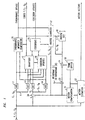
- Fig. 1 shows a block diagram of a color video encoder in accordance with an illustrative embodiment of the present invention.
- Fig. 2 shows a block diagram of a color video decoder, corresponding to the color video encoder of Fig. 1, in accordance with an illustrative embodiment of the present invention.
- Adaptive Video Coder with Dynamic Bit Allocation is an extension of a video coding system described in detail in co-pending patent application "Adaptive Video Coder with Dynamic Bit Allocation," by John Hartung, Ser. No. 08/248,982, filed on May 25, 1994 and assigned to the assignee of the present invention.
- "Adaptive Video Coder with Dynamic Bit Allocation” which has been allowed and for which the issue fee has been paid, is hereby incorporated by reference as if fully set forth herein.
- the coding system in accordance with an illustrative embodiment of the present invention comprises a forward adaptive codebook scheme, in which information from the frame to be coded is used to modify the codebook.
- adaptive codebooks which are described, for example, in Chapter 11 of Gersho and Gray, change over time in an attempt to provide a better match to the local statistics of the signal being coded. That is, the codebook, and thereby the coder, adapts to the characteristics of the signal. In a video application, such an approach can result in an improved quality of the decoded video, since the coder is, in effect, adapting itself to the given scene ( i.e., the particular objects and motion contained therein).
- Forward adaptive codebook schemes in particular use information from the frame to be coded to modify and, hopefully, thereby improve, the codebook. Such techniques typically replace one or more of the codebook entries with new entries before coding the current frame. Blocks which might otherwise not be coded well (i.e., coded with too large an error) might form the basis of a new codebook entry, thereby, e.g., resulting in an improved or even error-free coding of the given block.
- additional information known as "side" information, has to be separately coded and transmitted by these forward adaptive techniques, so that the current frame can be properly decoded by the decoder.
- Fig. 1 shows a block diagram of a color video encoder in accordance with this illustrative embodiment of the present invention
- Fig. 2 shows a block diagram of a corresponding decoder.
- the basic components of the illustrative encoder include a block-based motion-compensated predictor and a hybrid scalar/vector quantizer which adapts to the changing characteristics of the input video sequence.
- the input sequence provided to the illustrative coder is furnished in the well-known standard format know as CIF (Common Intermediate Format).
- Each frame of the input CIF sequence is specified in terms of its luminance component (Y) and two chrominance components (C r and C b ).
- the chrominance components are advantageously subsampled by two in both the horizontal and vertical directions since their spatial bandwidth is known to be about 1/3 of that of the luminance component.
- the first step in the illustrative video coding system is to further downsample the luminance by a factor of 3 and the chrominance components by a factor of 6 both horizontally and vertically. Consequently, the two chroma channels are reduced to 1/4 the luminance resolution in each of the horizontal and vertical directions.
- the successive downsampled frames are partitioned into blocks of size 8 x 8 for the luminance and 2 x 2 for the chrominance.
- the video input signal (labeled as Y, C r , C b ) is presumed to have already been downsampled and partitioned in this manner.
- Blocks in a given frame are encoded using one of two basic techniques --interframe coding and intraframe coding.
- interframe mode the coder operates on the motion-compensated difference blocks while, in intraframe mode, the coder operates directly on the data in the blocks.
- intraframe mode the coder operates directly on the data in the blocks.
- the 8 x 8 luminance blocks are transformed into the frequency domain with use of a DCT (Discrete Cosine Transformation), while the 2 x 2 chrominance blocks are reduced to 1 x I scalar blocks by performing an averaging operation.
- the chrominance data is thereby encoded at 1/8 of the luminance resolution in each of the horizontal and vertical directions.
- DCT 12 transforms intraframe block luminance data into the frequency domain; averager 11 performs an averaging operation on an intraframe block of chrominance data; DCT 13 transforms interframe block luminance data into the frequency domain; and averager 14 performs an averaging operation on an interframe block of chrominance data.
- the transformed luminance and chrominance blocks are vector quantized by quantizer 15 with use of codebooks 25.
- Codebooks 25 comprise both interframe and intraframe codebooks, each containing both luminance and chrominance data.
- the quantized data may be advantageously entropy coded before being stored or transmitted to the decoder. (Entropy coders and decoders, which are conventional, are not shown in Figs. 1 or 2). Note that the scalar chrominance values are quantized directly since, in this case, the DCT does not provide significant additional compression.
- adder 19 adds the inverse quantized difference data to a (motion compensated) corresponding block from the previously stored frame, as passed from motion compensation 21 via multiplier 23.
- multiplier 23 multiplies the previously stored frame block by 0 for intraframe coded blocks and by 1 for interframe coded blocks, thereby causing adder 19 to have no effect on data from intraframe coded blocks, but the above-mentioned additive effect for interframe coded blocks.
- the illustrative vector quantizer adapts and learns about the characteristics of the scene as the sequence progresses.
- two adaptive codebooks one for encoding the difference blocks (interframe codebook) and one for encoding the data blocks (intraframe codebook)
- codebooks 25 are generated and continuously updated by codebook update 16.
- codebook update 16 also sends these updates (which may advantageously be in the form of entropy coded update vectors) to the decoder, so that the decoder codebooks can be correspondingly updated.
- new codebooks are formed by replacing the "less useful" vectors in the current codebooks by new vectors such that the resulting set of vectors better represent the spatial content of the scene.
- determining the best codevector, as well as deciding on which codebook to use and when to update a codebook is based on reducing the distortion (i.e., error) in the luminance component and on minimizing the number of bits per update.
- the mean-square error is used as the measure of distortion.
- motion estimation 22 compares the previously stored frame from frame buffer 20 with the current block to be coded and determines the motion vectors in a conventional manner. These motion vectors may be entropy coded (not shown in Fig. 1) before being stored or transmitted to the decoder.
- Motion compensation 21 uses the motion vectors to form a prediction block (based on the previously stored frame) to be used by subtracter 24 in computing difference data for (potential) use in interframe coding of the current block.
- the interframe and intraframe codebooks are empty (e.g., initialized to constant black vectors).
- the codebooks progressively get generated and updated by codebook update 16 to reflect the changing characteristics of the input sequence. Blocks are quantized in the order of decreasing luminance prediction error. For a block B, if the resulting luminance quantization error is large (as compared, for example, to a given threshold), this block may be used in updating either the interframe or intraframe codebook.
- the codebook update is performed by sending an update vector consisting of the luminance and chrominance components of either the difference (interframe) block corresponding to B or of the actual data (intraframe) block B, whichever one of the two requires fewer bits for storage or transmission to the decoder.
- the update vector can then be utilized to modify and improve the corresponding codebook such that the overall distortion is minimized.
- the update vector is simply inserted in the appropriate interframe or intraframe codebook by replacing the least used and, thereby, the presumably least representative codevector. This new codevector would then represent the best possible match for encoding block B.
- the codebook adaptation is done at the expense of vector quantizing fewer blocks. This is because the above quantization/update steps are repeated for blocks with decreasing (luminance) prediction error until the allowed fixed number of bits per frame has been consumed.
- pairs of correlated luminance and chrominance vectors are combined into an update vector and stored in the same codebook entry. That is, only one index is used to code both the luminance and chrominance content of an image block by selecting the best codebook vector based solely on the best luminance match. Consequently, the codebook size (i.e., the number of entries) and the bit rate are not expanded to accommodate the chrominance information. However, the best luminance match might not always correspond to a good chrominance match.
- the update and quantization steps aim at minimizing the distortion in the luminance, since the luminance data contains the most significant feature information.
- blocks with a small distortion in their luminance content might still have a large chrominance distortion which is, in fact, not improved by the update and quantization steps.
- These blocks may result in visually distracting artifacts since the color in a large block (e.g., 24 x 24 in a reconstructed CIF frame) may be incorrect.
- it is advantageous to correct for such a chrominance mismatch in accordance with an illustrative embodiment of the present invention.
- the illustrative embodiment of the present invention shown in Fig. 1 advantageously corrects for such a chrominance mismatch without introducing significant overhead, adding at most a 1-bit correction symbol for each block.
- chrominance mismatch comparator 26 of the illustrative encoder of Fig. 1 compares the coded chrominance data as generated from quantizer 15 with the original, uncoded chrominance data provided by averager 11 to determine the resultant coding error. In particular, it compares the resultant coding error with that which would result if the chrominance data from the interframe predicted block were used directly (i.e., without difference data from the interframe codebook being added thereto).
- the data provided by averager 14 is, of course, precisely that latter error.
- the chrominance bypass signal is activated for the given block.
- the activation of the chrominance bypass signal informs the decoder (and the decoder "portion" of the encoder) that the quantized (i.e., codebook-based) data is to be used to decode the luminance information, but the interframe prediction data is to be used to decode the chrominance information.
- the codebooks will not be used for the chrominance information when they would, in fact, do a poor job of coding such information.
- inverse quantizer 17 of the encoder in addition to providing the chrominance bypass signal to the decoder, it is provided to inverse quantizer 17 of the encoder (since the illustrative encoder of Fig. 1 advantageously includes decoding circuitry for use in interframe coding). In this manner, inverse quantizer 17 can "decode" the chrominance information by directly using the interframe predicted block chrominance data whenever the chrominance bypass signal has been activated.
- the most noticeable distortions in the chrominance content are mainly produced by two types of blocks: the intraframe encoded blocks which were not used in the update step and the non-quantized predicted blocks with non-zero motion vectors.
- the number of such blocks per frame is typically small. Therefore, in one illustrative embodiment of the present invention, the 1-bit correction symbol may advantageously be provided only for each block corresponding to one of the aforementioned types, thereby introducing even less overhead than 1-bit per coded block.
- Fig. 2 shows a block diagram of a color video decoder, corresponding to the color video encoder of Fig. 1, in accordance with an illustrative embodiment of the present invention.
- the operation of the illustrative decoder of Fig. 2 is similar to that of the decoder "portion" of the illustrative encoder of Fig. 1 and described above.
- an inverse quantization is performed by inverse quantizer 31 and an inverse DCT transformation for the luminance data is performed by inverse DCT 33.
- Codebooks 32 provide the codebook vectors for use by inverse quantizer 31 in decoding the encoded signals.
- inverse quantizer if the chrominance bypass signal is activated for a given block, inverse quantizer generates the decoded chrominance data for that block based on the (motion compensated) interframe prediction, rather than based on the chrominance data extracted from the codebook.
- adder 34 adds the inverse quantized difference data to the (motion compensated) corresponding block from the previously stored frame as passed by multiplier 35. Specifically, multiplier 35 multiplies the previously stored frame block by 0 for intraframe coded blocks and by 1 for interframe coded blocks, thereby causing adder 34 to have no effect on data from intraframe coded blocks, but the above-mentioned additive effect for interframe coded blocks.
- the reconstructed frame data in addition to being provided as the decoder output, is stored in frame buffer 36 for use in interframe coding for subsequent frames.
- motion compensation 37 uses the motion vectors supplied by the encoder to form a prediction block (based on the previously stored frame) to be used in decoding interframe coded blocks in subsequent frames and, in accordance with the illustrative embodiment of the present invention, to be used by inverse quantizer 31 for chrominance data when the chrominance bypass signal has been activated.
- the illustrative embodiment of the present invention is presented as comprising individual functional blocks.
- the functions these blocks represent may be provided through the use of either shared or dedicated hardware, including, but not limited to, hardware capable of executing software.
- the functions of blocks presented in Figs. 1 and 2 may be provided by individual processors or by a single shared processor. (Use of the term "processor” should not be construed to refer exclusively to hardware capable of executing software.)
- Illustrative embodiments may comprise digital signal processor (DSP) hardware, such as the AT&T DSP16 or DSP32C, read-only memory (ROM) for storing software performing the operations discussed below, and random access memory (RAM) for storing DSP results.
- DSP digital signal processor
- ROM read-only memory
- RAM random access memory
- VLSI Very large scale integration
Landscapes
- Engineering & Computer Science (AREA)
- Multimedia (AREA)
- Signal Processing (AREA)
- Physics & Mathematics (AREA)
- General Physics & Mathematics (AREA)
- Theoretical Computer Science (AREA)
- Compression Or Coding Systems Of Tv Signals (AREA)
- Color Television Systems (AREA)
- Compression, Expansion, Code Conversion, And Decoders (AREA)
Applications Claiming Priority (2)
| Application Number | Priority Date | Filing Date | Title |
|---|---|---|---|
| US08/519,867 US5748242A (en) | 1995-08-25 | 1995-08-25 | Color video vector quantization with chrominance codebook bypass |
| US519867 | 1995-08-25 |
Publications (1)
| Publication Number | Publication Date |
|---|---|
| EP0762783A2 true EP0762783A2 (de) | 1997-03-12 |
Family
ID=24070141
Family Applications (1)
| Application Number | Title | Priority Date | Filing Date |
|---|---|---|---|
| EP96306131A Withdrawn EP0762783A2 (de) | 1995-08-25 | 1996-08-22 | Verfahren und Vorrichtung zur Kodierung der Chrominanzinformation in einem Farbvideokoder mit niedriger Datenrate |
Country Status (4)
| Country | Link |
|---|---|
| US (1) | US5748242A (de) |
| EP (1) | EP0762783A2 (de) |
| JP (1) | JPH09163405A (de) |
| CA (1) | CA2183801A1 (de) |
Families Citing this family (23)
| Publication number | Priority date | Publication date | Assignee | Title |
|---|---|---|---|---|
| DE19652362A1 (de) * | 1996-12-17 | 1998-06-18 | Thomson Brandt Gmbh | Verfahren und Vorrichtung zur Kompensation der durch die Verarbeitung von Chrominanz-Signalen entstehenden Luminanzdefekte |
| US6133853A (en) * | 1998-07-30 | 2000-10-17 | American Calcar, Inc. | Personal communication and positioning system |
| US6650773B1 (en) * | 2000-09-29 | 2003-11-18 | Hewlett-Packard Development Company, L.P. | Method including lossless compression of luminance channel and lossy compression of chrominance channels |
| US6678590B1 (en) * | 2000-10-17 | 2004-01-13 | Bbnt Solutions Llc | Vehicle navigation system with vision system preprocessor using MPEG encoder |
| KR101014660B1 (ko) * | 2003-10-24 | 2011-02-16 | 삼성전자주식회사 | 인트라 예측 방법 및 장치 |
| EP1679902A3 (de) * | 2005-01-06 | 2012-04-25 | Qualcomm Incorporated | Residualcodierung für einen Videostandard mit nichtstandardisierter Vektorquantisierung |
| US7199735B1 (en) | 2005-08-25 | 2007-04-03 | Mobilygen Corporation | Method and apparatus for entropy coding |
| US8059712B2 (en) | 2006-01-13 | 2011-11-15 | Adobe Systems Incorporated | Independently adjusting the quality levels for luminance and chrominance channels in a digital image |
| JP4853199B2 (ja) * | 2006-09-25 | 2012-01-11 | 株式会社ニコン | 画像圧縮方法、装置、電子カメラ、およびプログラム |
| EP2448270A1 (de) * | 2006-10-10 | 2012-05-02 | Nippon Telegraph And Telephone Corporation | Videokodierungs- und -dekodierungsverfahren, Vorrichtungen und Programm dafür und Speichermedien zum Aufzeichnen der Programme |
| JP2008227689A (ja) * | 2007-03-09 | 2008-09-25 | Seiko Epson Corp | 符号化装置及び画像記録装置 |
| US8326075B2 (en) | 2008-09-11 | 2012-12-04 | Google Inc. | System and method for video encoding using adaptive loop filter |
| JP5215951B2 (ja) * | 2009-07-01 | 2013-06-19 | キヤノン株式会社 | 符号化装置及びその制御方法、コンピュータプログラム |
| US8503528B2 (en) * | 2010-09-15 | 2013-08-06 | Google Inc. | System and method for encoding video using temporal filter |
| US8780996B2 (en) | 2011-04-07 | 2014-07-15 | Google, Inc. | System and method for encoding and decoding video data |
| US8781004B1 (en) | 2011-04-07 | 2014-07-15 | Google Inc. | System and method for encoding video using variable loop filter |
| US8780971B1 (en) | 2011-04-07 | 2014-07-15 | Google, Inc. | System and method of encoding using selectable loop filters |
| US8885706B2 (en) | 2011-09-16 | 2014-11-11 | Google Inc. | Apparatus and methodology for a video codec system with noise reduction capability |
| US9131073B1 (en) | 2012-03-02 | 2015-09-08 | Google Inc. | Motion estimation aided noise reduction |
| US9344729B1 (en) | 2012-07-11 | 2016-05-17 | Google Inc. | Selective prediction signal filtering |
| US10102613B2 (en) | 2014-09-25 | 2018-10-16 | Google Llc | Frequency-domain denoising |
| US9270295B1 (en) * | 2015-05-06 | 2016-02-23 | The Boeing Company | Lossless compression of data based on a modified differential pulse code modulation (DPCM) scheme |
| GB201510652D0 (en) * | 2015-06-17 | 2015-07-29 | Beers Uk De Ltd | Colour measurement of gemstones |
Family Cites Families (4)
| Publication number | Priority date | Publication date | Assignee | Title |
|---|---|---|---|---|
| US4987480A (en) * | 1989-07-11 | 1991-01-22 | Massachusetts Institute Of Technology | Multiscale coding of images |
| US5255090A (en) * | 1991-11-19 | 1993-10-19 | Scientific-Atlanta, Inc. | Progressive transmission of vector quantized data |
| US5467413A (en) * | 1993-05-20 | 1995-11-14 | Radius Inc. | Method and apparatus for vector quantization for real-time playback on low cost personal computers |
| US5457495A (en) * | 1994-05-25 | 1995-10-10 | At&T Ipm Corp. | Adaptive video coder with dynamic bit allocation |
-
1995
- 1995-08-25 US US08/519,867 patent/US5748242A/en not_active Expired - Lifetime
-
1996
- 1996-08-21 CA CA002183801A patent/CA2183801A1/en not_active Abandoned
- 1996-08-22 EP EP96306131A patent/EP0762783A2/de not_active Withdrawn
- 1996-08-26 JP JP8223513A patent/JPH09163405A/ja active Pending
Also Published As
| Publication number | Publication date |
|---|---|
| CA2183801A1 (en) | 1997-02-26 |
| US5748242A (en) | 1998-05-05 |
| JPH09163405A (ja) | 1997-06-20 |
Similar Documents
| Publication | Publication Date | Title |
|---|---|---|
| US5748242A (en) | Color video vector quantization with chrominance codebook bypass | |
| US5457495A (en) | Adaptive video coder with dynamic bit allocation | |
| US6414992B1 (en) | Optimal encoding of motion compensated video | |
| EP2319241B1 (de) | Skip-modi zur kodierung und dekodierung von zwischenschicht-restvideoinhalten | |
| EP0615384B1 (de) | Adaptive Komprimierung von digitalen Videodaten | |
| US5155594A (en) | Hierarchical encoding method and apparatus employing background references for efficiently communicating image sequences | |
| EP0871336B1 (de) | Verfahren und Vorrichtung zur prädiktiven Bildkodierung und -dekodierung | |
| US6625215B1 (en) | Methods and apparatus for context-based inter/intra coding mode selection | |
| US5489944A (en) | Encoding method and apparatus to determine quantization levels using energy characteristics in the DCT domain | |
| US10027962B2 (en) | System, method and computer-readable medium for encoding a signal into macroblocks | |
| US20060153294A1 (en) | Inter-layer coefficient coding for scalable video coding | |
| US20070189626A1 (en) | Video encoding/decoding method and apparatus | |
| US7177356B2 (en) | Spatially transcoding a video stream | |
| US20040234142A1 (en) | Apparatus for constant quality rate control in video compression and target bit allocator thereof | |
| KR19980017213A (ko) | 열화영상에 대한 보상기능을 갖는 영상 복호화 시스템 | |
| US5627601A (en) | Motion estimation with bit rate criterion | |
| US7245773B2 (en) | Method and system for coding or decoding of a series of images | |
| Illgner et al. | Hierarchical coding of motion vector fields | |
| Netravali et al. | A high quality digital HDTV codec | |
| Westerink et al. | Subband coding of image sequences at low bit rates | |
| KR100335606B1 (ko) | 반복적움직임예측/보상을이용한영상부호화기및/또는복호화기 | |
| Karam et al. | Chroma coding for video at very low bit rates | |
| GB2316828A (en) | Compensating quantization errors of a decoded video signal by using an adaptive filter | |
| KR100196847B1 (ko) | 영상 신호의 대역별 차분 펄스 부호 변조 회로 | |
| Schamel et al. | Subband-based hybrid HDTV coding |
Legal Events
| Date | Code | Title | Description |
|---|---|---|---|
| PUAI | Public reference made under article 153(3) epc to a published international application that has entered the european phase |
Free format text: ORIGINAL CODE: 0009012 |
|
| AK | Designated contracting states |
Kind code of ref document: A2 Designated state(s): DE FR GB |
|
| STAA | Information on the status of an ep patent application or granted ep patent |
Free format text: STATUS: THE APPLICATION HAS BEEN WITHDRAWN |
|
| 18W | Application withdrawn |
Withdrawal date: 19990624 |