EP0762627B1 - Verfahren zur Regelung einer Drehfeldmaschine - Google Patents
Verfahren zur Regelung einer Drehfeldmaschine Download PDFInfo
- Publication number
- EP0762627B1 EP0762627B1 EP96810528A EP96810528A EP0762627B1 EP 0762627 B1 EP0762627 B1 EP 0762627B1 EP 96810528 A EP96810528 A EP 96810528A EP 96810528 A EP96810528 A EP 96810528A EP 0762627 B1 EP0762627 B1 EP 0762627B1
- Authority
- EP
- European Patent Office
- Prior art keywords
- supply voltage
- voltage
- change
- induction machine
- magnetic flux
- Prior art date
- Legal status (The legal status is an assumption and is not a legal conclusion. Google has not performed a legal analysis and makes no representation as to the accuracy of the status listed.)
- Expired - Lifetime
Links
- 230000004907 flux Effects 0.000 claims abstract description 48
- 230000008859 change Effects 0.000 claims abstract description 24
- 238000000034 method Methods 0.000 claims abstract description 21
- 230000003111 delayed effect Effects 0.000 claims abstract 4
- 230000006698 induction Effects 0.000 claims description 26
- 238000001914 filtration Methods 0.000 claims description 5
- 230000001681 protective effect Effects 0.000 description 6
- 230000033228 biological regulation Effects 0.000 description 5
- 239000003990 capacitor Substances 0.000 description 5
- 230000008569 process Effects 0.000 description 3
- 230000001419 dependent effect Effects 0.000 description 2
- 230000003313 weakening effect Effects 0.000 description 2
- 230000008901 benefit Effects 0.000 description 1
- 238000006243 chemical reaction Methods 0.000 description 1
- 230000001276 controlling effect Effects 0.000 description 1
- 238000010586 diagram Methods 0.000 description 1
- 230000000694 effects Effects 0.000 description 1
- 230000005611 electricity Effects 0.000 description 1
- 230000000763 evoking effect Effects 0.000 description 1
- 238000010409 ironing Methods 0.000 description 1
- 230000005415 magnetization Effects 0.000 description 1
- 230000007257 malfunction Effects 0.000 description 1
- 238000005259 measurement Methods 0.000 description 1
- 238000011084 recovery Methods 0.000 description 1
- 230000001105 regulatory effect Effects 0.000 description 1
- 230000000630 rising effect Effects 0.000 description 1
- 238000000926 separation method Methods 0.000 description 1
- 230000002123 temporal effect Effects 0.000 description 1
- 230000007704 transition Effects 0.000 description 1
- 230000001960 triggered effect Effects 0.000 description 1
Images

Classifications
-
- B—PERFORMING OPERATIONS; TRANSPORTING
- B60—VEHICLES IN GENERAL
- B60L—PROPULSION OF ELECTRICALLY-PROPELLED VEHICLES; SUPPLYING ELECTRIC POWER FOR AUXILIARY EQUIPMENT OF ELECTRICALLY-PROPELLED VEHICLES; ELECTRODYNAMIC BRAKE SYSTEMS FOR VEHICLES IN GENERAL; MAGNETIC SUSPENSION OR LEVITATION FOR VEHICLES; MONITORING OPERATING VARIABLES OF ELECTRICALLY-PROPELLED VEHICLES; ELECTRIC SAFETY DEVICES FOR ELECTRICALLY-PROPELLED VEHICLES
- B60L3/00—Electric devices on electrically-propelled vehicles for safety purposes; Monitoring operating variables, e.g. speed, deceleration or energy consumption
- B60L3/0023—Detecting, eliminating, remedying or compensating for drive train abnormalities, e.g. failures within the drive train
-
- H—ELECTRICITY
- H02—GENERATION; CONVERSION OR DISTRIBUTION OF ELECTRIC POWER
- H02P—CONTROL OR REGULATION OF ELECTRIC MOTORS, ELECTRIC GENERATORS OR DYNAMO-ELECTRIC CONVERTERS; CONTROLLING TRANSFORMERS, REACTORS OR CHOKE COILS
- H02P29/00—Arrangements for regulating or controlling electric motors, appropriate for both AC and DC motors
- H02P29/02—Providing protection against overload without automatic interruption of supply
- H02P29/024—Detecting a fault condition, e.g. short circuit, locked rotor, open circuit or loss of load
- H02P29/025—Detecting a fault condition, e.g. short circuit, locked rotor, open circuit or loss of load the fault being a power interruption
-
- H—ELECTRICITY
- H02—GENERATION; CONVERSION OR DISTRIBUTION OF ELECTRIC POWER
- H02P—CONTROL OR REGULATION OF ELECTRIC MOTORS, ELECTRIC GENERATORS OR DYNAMO-ELECTRIC CONVERTERS; CONTROLLING TRANSFORMERS, REACTORS OR CHOKE COILS
- H02P29/00—Arrangements for regulating or controlling electric motors, appropriate for both AC and DC motors
- H02P29/02—Providing protection against overload without automatic interruption of supply
- H02P29/024—Detecting a fault condition, e.g. short circuit, locked rotor, open circuit or loss of load
- H02P29/026—Detecting a fault condition, e.g. short circuit, locked rotor, open circuit or loss of load the fault being a power fluctuation
-
- B—PERFORMING OPERATIONS; TRANSPORTING
- B60—VEHICLES IN GENERAL
- B60L—PROPULSION OF ELECTRICALLY-PROPELLED VEHICLES; SUPPLYING ELECTRIC POWER FOR AUXILIARY EQUIPMENT OF ELECTRICALLY-PROPELLED VEHICLES; ELECTRODYNAMIC BRAKE SYSTEMS FOR VEHICLES IN GENERAL; MAGNETIC SUSPENSION OR LEVITATION FOR VEHICLES; MONITORING OPERATING VARIABLES OF ELECTRICALLY-PROPELLED VEHICLES; ELECTRIC SAFETY DEVICES FOR ELECTRICALLY-PROPELLED VEHICLES
- B60L2200/00—Type of vehicles
- B60L2200/26—Rail vehicles
-
- Y—GENERAL TAGGING OF NEW TECHNOLOGICAL DEVELOPMENTS; GENERAL TAGGING OF CROSS-SECTIONAL TECHNOLOGIES SPANNING OVER SEVERAL SECTIONS OF THE IPC; TECHNICAL SUBJECTS COVERED BY FORMER USPC CROSS-REFERENCE ART COLLECTIONS [XRACs] AND DIGESTS
- Y02—TECHNOLOGIES OR APPLICATIONS FOR MITIGATION OR ADAPTATION AGAINST CLIMATE CHANGE
- Y02T—CLIMATE CHANGE MITIGATION TECHNOLOGIES RELATED TO TRANSPORTATION
- Y02T10/00—Road transport of goods or passengers
- Y02T10/60—Other road transportation technologies with climate change mitigation effect
- Y02T10/64—Electric machine technologies in electromobility
Definitions
- the invention is based on a method for Regulation of a three-phase machine according to the preamble of Claim 1.
- the invention takes to a state of the art, as it is from a Publication by H. P. Bauer and M. Buschmann, CONTROL SYSTEM FOR A THREE PHASE GTO INVERTER FOR MASS TRANSIT APPLICATIONS, EPE-Proceedings, Firenze (1991) Issue 4, p. 638 - 643, is known.
- induction machines become one Subway operated with direct self-regulation and off fed into a DC voltage network via inverters. there is a voltage drop in the DC network corrected, but on the problem of a fast Voltage recovery not received.
- a control device is described in DE 31 15 538 A1 specified for an induction machine.
- the method described in 538 A1 aims exclusively at this from the influence of the secondary current and the Magnetization current caused changes in the magnetic Flow by means of a regular frequency intervention trying to suppress in the primary current.
- the invention as defined in claim 1 solves the task; a method for controlling a three-phase machine of the type mentioned in such a way that a Tilting of the induction machine due to fluctuations in the Supply voltage, especially when rising, is avoided.
- An advantage of the invention is that less Malfunctions occur, especially in field weakening operations a three-phase machine.
- the method according to the invention can easily be applied to existing ones Transfer regulations because both the increase to be monitored of the magnetic flux, the filter time constant of the Voltage filtering and also the permissible deviation of the Supply voltage are easy to grasp. These monitors and Recordings can be carried out in parallel to normal regulation become.
- the controller remains active even in the event of a fault / problem; it is "overruled” only briefly by zero voltage pulses. However, this results in smooth transitions from Normal operation in the event of a fault and vice versa, in each If the drive remains active.
- Fig. 1 shows an induction or asynchronous or induction machine (2), which is fed via a 3-phase inverter (1) from a DC voltage source with a positive pole (P) and a negative pole (N) with a DC supply voltage (U d ) .
- a capacitor (C) is used to stabilize this DC supply voltage (U d ).
- the DC supply voltage (U d ) can, for. B. the DC link DC voltage of a converter, not shown, with a DC voltage intermediate circuit.
- the DC voltage intermediate circuit then forms the controlled system together with the inverter (1) and the induction machine (2) and the inverter (1) the actuator of the controlled system.
- Fast and dynamic control methods which are implemented on microprocessors, are suitable for control, e.g. B. the process of direct self-regulation.
- a torque controller (3) the input side an actual torque (M x ) and a z. B. from a not shown, higher-level regulation predeterminable torque setpoint (M r ) are supplied, on the output side provides a controller manipulated variable (S3) via an opener (4) to an ignition pulse converter (5). On the output side, this supplies inverter control signals (S R , S S , S T ) for 3 alternating current phases (R, S, T) to the inverter (1).
- a function transmitter (6) receives these inverter control signals (S R , S S , S T ) on the input side, a signal proportional to the DC supply voltage (U d ) and actual phase current signals (i R , i S , i T ) from the output of the inverter (1) and delivers them on the output side a signal proportional to the magnitude of the magnetic stator flux ( ⁇ s ) to a differentiating element (7). It is sufficient if instead of 3 actual phase current values (i R , i S , i T ) only 2 are specified and the 3rd is calculated using the current sum.
- the calculation of the magnetic stator flux ( ⁇ s ) can e.g. B. according to the calculations of the above-mentioned thesis.
- the differentiator (7) supplies a signal proportional to the magnetic flux change ( ⁇ s ) to a non-negating input of a first comparator (8), at the negating input of which there is a predeterminable limit value for the magnetic flux change ( ⁇ sr ) and the output side via an AND Member (9) is in control connection with a control input of the break contact (4). If the output signal of the AND gate (9) is 0, the break contact (4) is closed, otherwise it is open for a predeterminable time period in the range from 150 ⁇ s to 500 ms.
- the limit value of the magnetic flux change ( ⁇ sr ) corresponds to the time constant of the rotor of the induction machine (2); it is chosen so that the induction machine (2) would "tilt” if the magnetic flux change ( ⁇ s ) exceeded this limit.
- the rotor time constant results from the ratio of leakage inductance to rotor resistance of the induction machine (2); it determines the possible rate of flow increase.
- the increase in the magnetic stator flux ( ⁇ s ) becomes faster than the rotor time constant, the rotor flux would no longer be able to follow the magnetic stator flux ( ⁇ s ) if the drive were driven for a longer period of time and the tilting field machine (2) would "tilt". For this reason, the increase in the magnetic stator flux ( ⁇ s ) must be monitored.
- a 1st protective measure criterion for an impermissible voltage rise is fulfilled if the magnetic stator flux rise ( ⁇ s ) is faster than the rotor flux rise, which can only be done with the rotor time constant.
- the stator flux increase ( ⁇ s ) is therefore compared in the comparator (8) with the maximum permissible rotor flux increase ( ⁇ sr ).
- a PT1 filter or low-pass filter (10) is fed on the input side with the signal proportional to the DC supply voltage (U d ) and a predeterminable cut-off or cut-off frequency (f e ) in a frequency range from 5 Hz to 20 Hz; on the output side, it supplies a filtered voltage signal (U F ) to a negating input of a second comparator (11), which is connected on the output side to a second input of the AND gate (9).
- the cut-off frequency (f e ) is selected so that harmonics contained in the DC supply voltage (U d ) cannot pass through the low-pass filter (10).
- the signal proportional to the DC supply voltage (U d ) is fed to a non-negating input of the comparator (11) and a predeterminable voltage difference limit value ( ⁇ U r ) is fed to a further negating input.
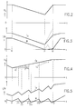
- FIG. 2 in which the supply voltage (U d ) is plotted on the ordinate and the time (t) is plotted on the abscissa, shows a rough overview of a drop in the supply voltage (U d ) in a DC voltage intermediate circuit.
- t0 a point in time
- the DC supply voltage (U d ) is held only by the energy contained in the capacitor (C) and begins to decrease as a result of the further load.
- the feed is active again and the DC supply voltage (U d ) rises steeply, since it is almost an undamped charging of the capacitor (C).
- This process is repeated with a zero voltage switching between the time (t13) and a time (t14) and with a subsequent build-up of the magnetic stator flux ( ⁇ s ) up to a time (t15), etc.
- This behavior causes the torque (M) to be 0 is maintained, and the current rise only occurs due to the flux build-up, which is reduced by the zero voltage circuits.
- the torque (M) can be adjusted. Then normal operation can be continued.
- Torque (M) can only be transmitted slightly in the time range from time (t1) to (t2), but after that the operation can continue without interruption, while without this intervention the system would have tilted and would then have to be restarted completely.
Landscapes
- Engineering & Computer Science (AREA)
- Power Engineering (AREA)
- Life Sciences & Earth Sciences (AREA)
- Sustainable Development (AREA)
- Sustainable Energy (AREA)
- Transportation (AREA)
- Mechanical Engineering (AREA)
- Control Of Ac Motors In General (AREA)
- Control Of Eletrric Generators (AREA)
Description
- Fig. 1
- ein Prinzipschaltbild einer Drehmomentregelschaltung einer Drehfeldmaschine,
- Fig. 2 und 4
- zeitliche Verläufe einer Speisegleichspannung für die Drehfeldmaschine und
- Fig. 3 und 5
- zeitliche Verläufe von Ständerstrom und Drehmoment der Drehfeldmaschine.
- 1
- Wechselrichter
- 2
- Drehfeldmaschine, Asynchronmaschine
- 3
- Drehmomentregler
- 4
- Öffner
- 5
- Zündimpulswandler
- 6
- Funktionsgeber
- 7
- Differenzierglied
- 8, 11
- 1. bzw. 2. Komparatoren
- 9
- UND-Glied
- 10
- Tiefpaßfilter
- C
- Kondensator, Zwischenkreiskondensator
- fe
- Eckfrequenz, Grenzfrequenz
- i
- Strom
- iR, iS, iT
- Phasenströme
- N
- negativer Pol
- M
- Drehmoment von 2
- Mr
- Drehmomentsollwert
- Mx
- Drehmomentistwert
- P
- positiver Pol
- R, S, T
- Wechselstromphasen
- S3
- Reglerstellgröße
- SR, SS, ST
- Wechselrichtersteuersignale
- t
- Zeit
- t0 - t15
- Zeitpunkte
- U
- Spannung
- Ud
- Speisegleichspannung
- UF
- Filterausgangsspannung, gefiltertes Spannungssignal
- ΔU
- Spannungsdifferenz
- ΔUr
- Spannungsdifferenzgrenzwert
- ψs
- magnetischer Ständerfluß
- Δψs
- magnetische Flußänderung
- Δψsr
- Grenzwert der magnetischen Flußänderung
Claims (8)
- Verfahren zur Regelung einer Drehfeldmaschine (2),dadurch gekennzeichnet,a) die durch mindestens einen Wechselrichter (1) aus einer Speisegleichspannung (Ud) versorgt wird,b) wobei ein magnetischer Ständerfluss (ψs) der Drehfeldmaschine (2) über diesen Wechselrichter (1) einstellbar ist,
c) dass die durch eine Änderung der Speisegleichspannung (Ud) hervorgerufene magnetische Flussänderung (Δψs) des Ständers der Drehfeldmaschine (2) reduziert wird, wenn diese Flussänderung (Δψs) einen ersten Grenzwert (Δψsr) überschreitet. - Verfahren nach Anspruch 1, dadurch gekennzeichnet, daß die magnetische Flußänderung (Δψs) des Ständers der Drehfeldmaschine (2) nur dann reduziert wird, wenn zusätzlich die Änderung (ΔU) der Speisegleichspannung (Ud) einen zweiten Grenzwert (ΔUr) überschreitet.
- Verfahren nach Anspruch 2, dadurch gekennzeichnet,a) daß die Speisegleichspannung (Ud) verzögert wird,b) daß die Amplitude dieser verzögerten Spannung (UF) mit der Amplitude der unverzögerten Speisegleichspannung (Ud) verglichen wird undc) daß die Differenz von verzögerter und unverzögerter Speisegleichspannung (Ud) als Maß für die Änderung (ΔU) der Speisegleichspannung (Ud) verwendet wird.
- Verfahren nach Anspruch 3, dadurch gekennzeichnet, daß die Verzögerung eine Tiefpaßfilterung ist.
- Verfahren nach einem der Ansprüche 3 oder 4, dadurch gekennzeichnet, daß bei der Verzögerung der Speisegleichspannung (Ud) mit derem aktuellem unverzögertem Wert begonnen wird, wenn die Flußreduzierung aktiviert wurde.
- Verfahren nach einem der vorhergehenden Ansprüche, dadurch gekennzeichnet, daß zur Reduzierung der magnetischen Flußänderung (ΔΨs) des Ständers der Drehfeldmaschine (2) während einer vorgebbaren Zeitdauer deren Stromklemmen auf ein reduziertes Potential gebracht werden.
- Verfahren nach einem der Ansprüche 1 bis 5, dadurch gekennzeichnet, daß zur Reduzierung der magnetischen Flußänderung (Δψs) des Ständers der Drehfeldmaschine (2) während einer vorgebbaren Zeitdauer deren Stromklemmen auf gleiches Potential gebracht werden.
- Verfahren nach Anspruch 6 oder 7, dadurch gekennzeichnet, daß die vorgebbare Zeitdauer im Bereich von 150 µs - 500 ms liegt.
Applications Claiming Priority (2)
| Application Number | Priority Date | Filing Date | Title |
|---|---|---|---|
| DE19533570A DE19533570C2 (de) | 1995-09-11 | 1995-09-11 | Verfahren zur Regelung einer Drehfeldmaschine |
| DE19533570 | 1995-09-11 |
Publications (2)
| Publication Number | Publication Date |
|---|---|
| EP0762627A1 EP0762627A1 (de) | 1997-03-12 |
| EP0762627B1 true EP0762627B1 (de) | 2001-03-28 |
Family
ID=7771839
Family Applications (1)
| Application Number | Title | Priority Date | Filing Date |
|---|---|---|---|
| EP96810528A Expired - Lifetime EP0762627B1 (de) | 1995-09-11 | 1996-08-09 | Verfahren zur Regelung einer Drehfeldmaschine |
Country Status (4)
| Country | Link |
|---|---|
| EP (1) | EP0762627B1 (de) |
| AT (1) | ATE200167T1 (de) |
| DE (1) | DE19533570C2 (de) |
| ES (1) | ES2155593T3 (de) |
Family Cites Families (5)
| Publication number | Priority date | Publication date | Assignee | Title |
|---|---|---|---|---|
| JPS6035918B2 (ja) * | 1980-04-16 | 1985-08-17 | 富士電機株式会社 | 交流電動機の制御装置 |
| JPH0714280B2 (ja) * | 1987-04-28 | 1995-02-15 | 富士電機株式会社 | 磁束制御形インバ−タの制御回路 |
| JPH027801A (ja) * | 1988-06-27 | 1990-01-11 | Toshiba Corp | 電気車の制御装置 |
| EP0491881B1 (de) * | 1989-09-07 | 1995-03-15 | Siemens Aktiengesellschaft | Verfahren zur flussollwertkorrektur einer umrichtergespeisten, mehrphasigen maschine und schaltungsanordnung zur durchführung des verfahrens |
| EP0519100B1 (de) * | 1991-06-19 | 1995-02-08 | Siemens Aktiengesellschaft | Verfahren und Einrichtung zum Begrenzen einer physikalischen Grösse, vorzugsweise einer elektrischen Spannung |
-
1995
- 1995-09-11 DE DE19533570A patent/DE19533570C2/de not_active Expired - Fee Related
-
1996
- 1996-08-09 EP EP96810528A patent/EP0762627B1/de not_active Expired - Lifetime
- 1996-08-09 AT AT96810528T patent/ATE200167T1/de not_active IP Right Cessation
- 1996-08-09 ES ES96810528T patent/ES2155593T3/es not_active Expired - Lifetime
Also Published As
| Publication number | Publication date |
|---|---|
| DE19533570C2 (de) | 1999-01-21 |
| ATE200167T1 (de) | 2001-04-15 |
| EP0762627A1 (de) | 1997-03-12 |
| DE19533570A1 (de) | 1997-03-13 |
| ES2155593T3 (es) | 2001-05-16 |
Similar Documents
| Publication | Publication Date | Title |
|---|---|---|
| DE3236692A1 (de) | Wechselrichter-system | |
| CH621656A5 (de) | ||
| EP0353569B1 (de) | Verfahren zur Vermeidung von Wechselrichterkippen bei einem Netzrückspeisestromrichter eines netzseitigen Umkehrstromrichters eines Spannungszwischenkreis-Umrichters bei dynamischer Spannungsabsenkung und Schaltungsanordnung zur Durchführung des Verfahrens | |
| DE69817427T2 (de) | Anlage für elektrische Leistungsübertragung | |
| EP0690556B1 (de) | Stillstandserkennung beim Wiederanlassen eines stromrichtergespeisten Drehstrommotors ohne Drehzahlgeber | |
| WO2008113307A1 (de) | Steuereinrichtung für stromrichterstationen bei einer hochspannungsgleichstromübertragungseinrichtung | |
| DE69117003T2 (de) | Regelvorrichtung für ein elektrisches Fahrzeug | |
| EP0142808B1 (de) | Verfahren und Vorrichtung zum Betrieb einer über einen Stromzwischenkreisumrichter gespeisten Asynchronmaschine bei Netzstörung | |
| EP0469177B1 (de) | Verfahren und Vorrichtung zum Wiederanlassen eines Induktionsmotors | |
| DE4442151A1 (de) | Schaltungsanordnung zum Steuern eines elektronisch kommutierten Motors | |
| DE3150396C2 (de) | Steuerungsverfahren zum Abbremsen eines Drehstommotors | |
| EP2144361B1 (de) | Verfahren und Vorrichtung zur Einstellung einer Rückspeiseleistung eines grundfrequent getakteten Stromrichters | |
| WO2018095632A1 (de) | Schutzvorrichtung für ein elektrisches antriebssystem, elektrisches antriebssystem und verfahren zum betrieb eines elektrischen antriebssystems | |
| WO2017084857A1 (de) | Verfahren zum erkennen eines fehlers in einer generatoreinheit | |
| EP3138192A1 (de) | Vorrichtung zum betreiben eines gleichrichters, insbesondere einer halbgesteuerten gleichrichterbrücke, und verfahren zum betreiben eines gleichrichters | |
| DE102006051352C5 (de) | Verfahren zum Betreiben einer Windenergieanlage | |
| DE19533570C2 (de) | Verfahren zur Regelung einer Drehfeldmaschine | |
| EP0216143A2 (de) | Schaltungsanordnung zur Steuerung des Anlaufens und Abbremsens von Drehstrom-Asynchronmotoren und Verfahren zum Betrieb einer derartigen Schaltungsanordnung | |
| DE19539915B4 (de) | Verfahren zur Überwachung wie Stillstands- und/oder Einrichtdrehzahlüberwachung eines Antriebs, insbesondere hochdynamischen Servoantriebs, sowie Lastrelais insbesondere zur Verwendung bei einem entsprechenden Verfahren | |
| DE10219826A1 (de) | Verfahren und Vorrichtung zur feldorientierten Regelung einer permanentmagneterregten Synchronmaschine | |
| DE4242665A1 (de) | Verfahren und Vorrichtung zum Rückschalten eines polumschaltbaren Motors | |
| DE4422275C2 (de) | Verfahren zum Betrieb von Drehstrommotoren | |
| WO2023180244A1 (de) | Hysterese basierte ansteuerung eines fahrzeugantriebs mit abwechselndem freilauf- und kurzschlusszustand im fehlerfall | |
| DE4316365C2 (de) | Steuerverfahren für einen Frequenzumrichter für den Anlauf, die Drehzahlverstellung, das Bremsen und Positionieren von Drehstrom-Asynchronmotoren | |
| DE2038907B2 (de) | Anordnung zur Drehzahlregelung einer Gleichstrommaschine |
Legal Events
| Date | Code | Title | Description |
|---|---|---|---|
| PUAI | Public reference made under article 153(3) epc to a published international application that has entered the european phase |
Free format text: ORIGINAL CODE: 0009012 |
|
| AK | Designated contracting states |
Kind code of ref document: A1 Designated state(s): AT ES GB IT SE |
|
| 17P | Request for examination filed |
Effective date: 19970809 |
|
| 17Q | First examination report despatched |
Effective date: 19990503 |
|
| RAP1 | Party data changed (applicant data changed or rights of an application transferred) |
Owner name: DAIMLERCHRYSLER AG |
|
| GRAG | Despatch of communication of intention to grant |
Free format text: ORIGINAL CODE: EPIDOS AGRA |
|
| GRAG | Despatch of communication of intention to grant |
Free format text: ORIGINAL CODE: EPIDOS AGRA |
|
| GRAH | Despatch of communication of intention to grant a patent |
Free format text: ORIGINAL CODE: EPIDOS IGRA |
|
| ITF | It: translation for a ep patent filed | ||
| GRAH | Despatch of communication of intention to grant a patent |
Free format text: ORIGINAL CODE: EPIDOS IGRA |
|
| GRAA | (expected) grant |
Free format text: ORIGINAL CODE: 0009210 |
|
| AK | Designated contracting states |
Kind code of ref document: B1 Designated state(s): AT ES GB IT SE |
|
| REF | Corresponds to: |
Ref document number: 200167 Country of ref document: AT Date of ref document: 20010415 Kind code of ref document: T |
|
| RAP2 | Party data changed (patent owner data changed or rights of a patent transferred) |
Owner name: DAIMLERCHRYSLER RAIL SYSTEMS GMBH |
|
| REG | Reference to a national code |
Ref country code: ES Ref legal event code: FG2A Ref document number: 2155593 Country of ref document: ES Kind code of ref document: T3 |
|
| GBT | Gb: translation of ep patent filed (gb section 77(6)(a)/1977) |
Effective date: 20010615 |
|
| EN | Fr: translation not filed | ||
| REG | Reference to a national code |
Ref country code: GB Ref legal event code: IF02 |
|
| PLBE | No opposition filed within time limit |
Free format text: ORIGINAL CODE: 0009261 |
|
| STAA | Information on the status of an ep patent application or granted ep patent |
Free format text: STATUS: NO OPPOSITION FILED WITHIN TIME LIMIT |
|
| 26N | No opposition filed | ||
| PGFP | Annual fee paid to national office [announced via postgrant information from national office to epo] |
Ref country code: GB Payment date: 20030724 Year of fee payment: 8 |
|
| PGFP | Annual fee paid to national office [announced via postgrant information from national office to epo] |
Ref country code: SE Payment date: 20030728 Year of fee payment: 8 |
|
| PGFP | Annual fee paid to national office [announced via postgrant information from national office to epo] |
Ref country code: AT Payment date: 20030729 Year of fee payment: 8 |
|
| PGFP | Annual fee paid to national office [announced via postgrant information from national office to epo] |
Ref country code: ES Payment date: 20030808 Year of fee payment: 8 |
|
| PG25 | Lapsed in a contracting state [announced via postgrant information from national office to epo] |
Ref country code: GB Free format text: LAPSE BECAUSE OF NON-PAYMENT OF DUE FEES Effective date: 20040809 Ref country code: AT Free format text: LAPSE BECAUSE OF NON-PAYMENT OF DUE FEES Effective date: 20040809 |
|
| PG25 | Lapsed in a contracting state [announced via postgrant information from national office to epo] |
Ref country code: SE Free format text: LAPSE BECAUSE OF NON-PAYMENT OF DUE FEES Effective date: 20040810 Ref country code: ES Free format text: LAPSE BECAUSE OF NON-PAYMENT OF DUE FEES Effective date: 20040810 |
|
| EUG | Se: european patent has lapsed | ||
| GBPC | Gb: european patent ceased through non-payment of renewal fee |
Effective date: 20040809 |
|
| PG25 | Lapsed in a contracting state [announced via postgrant information from national office to epo] |
Ref country code: IT Free format text: LAPSE BECAUSE OF NON-PAYMENT OF DUE FEES Effective date: 20050809 |
|
| REG | Reference to a national code |
Ref country code: ES Ref legal event code: FD2A Effective date: 20040810 |