EP0762126B1 - Verfahren und Vorrichtung zur Geschwindigkeitsmessung - Google Patents
Verfahren und Vorrichtung zur Geschwindigkeitsmessung Download PDFInfo
- Publication number
- EP0762126B1 EP0762126B1 EP96113119A EP96113119A EP0762126B1 EP 0762126 B1 EP0762126 B1 EP 0762126B1 EP 96113119 A EP96113119 A EP 96113119A EP 96113119 A EP96113119 A EP 96113119A EP 0762126 B1 EP0762126 B1 EP 0762126B1
- Authority
- EP
- European Patent Office
- Prior art keywords
- sub
- regions
- phase
- grating
- pairs
- Prior art date
- Legal status (The legal status is an assumption and is not a legal conclusion. Google has not performed a legal analysis and makes no representation as to the accuracy of the status listed.)
- Expired - Lifetime
Links
- 238000000034 method Methods 0.000 title claims description 23
- 238000011156 evaluation Methods 0.000 claims description 23
- 238000005259 measurement Methods 0.000 claims description 21
- 230000003287 optical effect Effects 0.000 claims description 16
- 230000010363 phase shift Effects 0.000 claims description 15
- 230000015572 biosynthetic process Effects 0.000 claims description 13
- 230000010354 integration Effects 0.000 claims description 9
- 230000033001 locomotion Effects 0.000 claims description 9
- 238000004364 calculation method Methods 0.000 claims description 7
- 238000001514 detection method Methods 0.000 claims description 4
- 239000011159 matrix material Substances 0.000 claims description 4
- 230000005693 optoelectronics Effects 0.000 claims description 4
- 238000009826 distribution Methods 0.000 claims description 3
- 230000000694 effects Effects 0.000 claims description 3
- 230000008878 coupling Effects 0.000 claims description 2
- 238000010168 coupling process Methods 0.000 claims description 2
- 238000005859 coupling reaction Methods 0.000 claims description 2
- 238000003384 imaging method Methods 0.000 claims description 2
- 238000005286 illumination Methods 0.000 claims 4
- 230000005540 biological transmission Effects 0.000 claims 2
- 238000006243 chemical reaction Methods 0.000 claims 2
- 238000005070 sampling Methods 0.000 description 25
- 230000006870 function Effects 0.000 description 10
- 238000012545 processing Methods 0.000 description 9
- 238000010586 diagram Methods 0.000 description 4
- 238000004599 local-density approximation Methods 0.000 description 3
- 238000001228 spectrum Methods 0.000 description 3
- 238000012935 Averaging Methods 0.000 description 2
- 238000009825 accumulation Methods 0.000 description 2
- 238000012432 intermediate storage Methods 0.000 description 2
- 239000002245 particle Substances 0.000 description 2
- 230000009466 transformation Effects 0.000 description 2
- 238000013459 approach Methods 0.000 description 1
- 238000012937 correction Methods 0.000 description 1
- 238000011161 development Methods 0.000 description 1
- 230000018109 developmental process Effects 0.000 description 1
- 238000001914 filtration Methods 0.000 description 1
- 238000000691 measurement method Methods 0.000 description 1
- 238000000819 phase cycle Methods 0.000 description 1
- 230000005855 radiation Effects 0.000 description 1
- 238000007493 shaping process Methods 0.000 description 1
- 239000007787 solid Substances 0.000 description 1
- 230000002123 temporal effect Effects 0.000 description 1
- 238000012360 testing method Methods 0.000 description 1
- 238000009827 uniform distribution Methods 0.000 description 1
Images



Classifications
-
- G—PHYSICS
- G01—MEASURING; TESTING
- G01P—MEASURING LINEAR OR ANGULAR SPEED, ACCELERATION, DECELERATION, OR SHOCK; INDICATING PRESENCE, ABSENCE, OR DIRECTION, OF MOVEMENT
- G01P3/00—Measuring linear or angular speed; Measuring differences of linear or angular speeds
- G01P3/36—Devices characterised by the use of optical means, e.g. using infrared, visible, or ultraviolet light
Definitions
- the invention relates to a method for determining the speed of an object or an object surface as a characteristic size of many industrial ones Processes relative to an opto-electronic speedometer. They are one Series of methods known, the filter effect of lattice-like structures exploit to generate a narrowband signal, the maximum frequency in the Power density spectrum is proportional to the object speed sought.
- DE 40 09 737 A1 describes an imaging sensor system from its output signal by multiplication with weight functions and subsequent Integration or averaging over the scanned image section several Evaluation signals are generated that form an electrical rotating field. With a Phase shift of 90 ° between the weight functions becomes a two-phase Rotating field, with a phase shift of 120 ° a three-phase rotating field.
- DE 33 40 924 A1 describes two phase-orthogonal signals by corresponding ones Interconnection of the output signals from at least one of four opto-electrical ones Converters generated existing group. From the two to one Quarterly shifted signals is done with the help of a logic circuit determines the direction of movement. However, on the speed of the Frequency of the signals closed.
- a comb-shaped nesting of two grids is also used in DE 32 29 343 A1 Generation of two phase-shifted signals used.
- the signal frequency becomes directly concluded on the speed. Again, the phase shift only serves to detect the direction of movement.
- JP 63-273064 A four detector element groups become two differential gratings interconnected. From the time difference of the zero crossings of the two signals, the Object speed determined. However, the phase angle is not determined suggested.
- DE-OS 24 54 299 proposes neighboring grid elements (at least 3) an optical grid to group together and on the one hand the Output signals of all the first and on the other hand the output signals of all the second Sum grid elements in adder circuits.
- the phase comparison of the two Sum signals enables detection of the direction of movement, that is, a correct speed measurement.
- DE 40 35 039 A1 describes the Use of a CCD line sensor as a grid-like detector suggested. Integration takes place in the shift registers of the CCD line Sensor area through charge accumulation, which is created by applying a 2-phase cycle is realized.
- the optical method for local speed measurement also includes Laser Doppler Velocimetry (H.E. Albrecht: Laser Doppler flow measurement. Academy-Verlag, Berlin, 1986).
- Laser Doppler Velocimeter which after the Cross-beam principle work, also use the spatial filter effect lattice-shaped Structures (in the form of interference fringes in the measurement volume Intersection of the two intersecting laser beams) to form a signal with a maximum frequency proportional to the sought speed in the power density spectrum.
- there is an estimate for this signal frequency Evaluation methods in the time domain (e.g. period measurement) and in the frequency domain (e.g. Fast Fourier Transformation) see C. Tropea: Performance Testing of LDA / PDA signal processing systems. Proc. 3rd Int. Conf. on laser anemometry advances and Applications, Swansea / UK, IL 4, 1989 and E.O. Principal Transformation. R. Oldenbourg Verlag, Kunststoff, Vienna, 1985).
- the object of the present invention is to use a suitable method Determine the frequency to make the speed information win, with the aim of increasing real-time capability and temporal resolution, and to simplify the signal processing and thus the computational effort to reduce the speed as a result with little measurement uncertainty to be able to determine highly dynamic processes.
- the object is achieved by a method according to claim 1 and a device according to claim 9.
- the speed measurement method uses one or more optoelectronic ones Detectors on which the movement of structured objects is mapped.
- This image information is subjected to an evaluation with grid-like functions that implement a light-dark modulation. All of the image information is additional rated with any window function.
- represents a spatial delimited detector is always a rectangle window rating that does that desired frequency spectrum of the resulting output signal disadvantageous influenced.
- the fenestration can already be in the optical channel e.g. through the Influencing the light intensity distribution or introducing an optical one Non-linearity take place, as well as afterwards through an electronic evaluation.
- the image information is processed in four locally different sub-areas each realize the evaluation with a grid-like function.
- the results of this Assessments are then integrated across the location.
- the procedure allows different approaches to integration. Integration can be done through immediate formation of the integral over the entire photosensitive surface of the four sub-areas. You can continue by linking immediately and summation take place or by sequential summation of the partial integrals via the photosensitive elementary areas of the four sub-areas can be realized.
- the four Subareas are nested in such a way that the two each form a pair Partial areas to each other a local phase shift of 90 ° (hereinafter as Phase orthogonality).
- the two couples have one another defined and in principle freely selectable local distance, the one Phase shift of preferably less than 90 ° corresponds.
- each of the four sub-areas generates its own narrowband signal.
- the signals of each signal pair are in one subsequent complex calculation as real or imaginary part of a complex size and each result in a rotating pointer.
- the signals of each signal pair lie in everyone Sampling time two pointers (a pair of pointers) in front.
- the phase angle at successive sampling times is a measure of the object speed sought.
- phase information is affected by phase jumps, so that the The present method provides for further signal processing.
- the method is used Rotary pointer pair. For each (sampling) time, in addition to those already calculated Phase angles of a signal pair at successive sampling times of the Phase angle between the two hands of the pair of rotating hands (and thus between the signal pairs). This phase angle results from the defined one Distance between the two area pairs, the reference value for those in the complex calculation rule integrated subsequent calculation of a corrected Phase angle is. This correction serves to eliminate the phase jumps and thus minimizing the measurement error. Finally, the object speed from the corrected phase angle determined.
- the starting point is an optical sensor 2 , which consists of an evaluation module 3 , two rotary pointer function modules 4 , two phase difference modules 5 and a speed module 6 ( FIG. 1 ).
- This basic arrangement includes different implementation variants, in particular in the execution of the evaluation module.
- a CCD line is particularly advantageous as an optoelectronic line Receiver array used.
- the lattice-like structure of this Receiver enables the orientation of the sensor to match the Axis of motion provided the one-dimensional measurement of the speed of Objects relative to the recipient.
- To generate two phase-orthogonal The sensor geometry is paired with a suitable timing and signal summary are used, with the geometry under sensor geometry the photosensitive surfaces of the CCD line should be understood. The required Integration over the photosensitive surfaces takes place through charge accumulation.
- n values of the output signal of the CCD line (sensor signal) separated by scanning and filtered with a low-pass filter are combined in the signal formation. This requires that these values be saved in a memory structure for each signal channel.
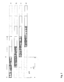
- Another variant is the use of a memory structure which is shared by the four signals and which is correspondingly addressable. The signal formation is shown schematically in FIG. 2 .
- the value pairs (a m , c m ) and (b m , d m ) are then interpreted as each consisting of a real and an imaginary component.
- the phase difference ⁇ ze between the current rotating pointer and the rotating pointer at the previous sampling instant is formed identically and for each of the two signal channels.
- the phase angles ⁇ between the rotation pointers of the two channels at the sampling time ( ⁇ m ) and at a previous sampling time ( ⁇ m-1 ) are determined in a suitable manner.
- a corrected phase value is determined from these four phase differences. This value is used to determine the speed.
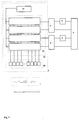
- Fig. 3 shows the embodiment of a sensor with a CCD line as a receiver array.
- the structure of a moving object 1 is mapped onto a receiver array designed as a CCD line 8 with the aid of optics 7 .
- a clock generator 9 realizes the clocking.
- the values of the output signal of the line are first temporarily stored in an addressable memory 10 to the extent required, which results from the combination of n of these values into one signal value.
- the sums of n / 2 values in each case are formed by summers 11 and fed to a differential gain 12 .
- the four signals obtained from the sensor signal in the manner described above are each subjected to filtering with a low-pass filter 13 of a higher order. This measure is used to eliminate interference frequencies.
- the two pairs of phase-orthogonal signals are then each transferred to a rotary pointer function module 4 for the formation of the rotary pointer.
- a phase difference module 5 per channel then realizes the calculation of the phase difference between the rotating pointers at the current and the previous sampling time, including the intermediate storage of the rotating pointer at the previous sampling time required for this.
- a speed module 6 finally determines the corrected phase and speed value for each sampling time from these two phase differences and the phase differences determined by this functional unit from the rotary pointers of both channels for the current and previous sampling time, as described above.
- the correct determination of the speed is based on the generation of two pairs of measurement signals by detection of scattered light from two pairs of distinguishable strip systems.
- the four locally different subregions correspond to two pairs of parallel, equidistant interference fringe patterns, each with an internal ⁇ / 2 phase shift.
- the two pairs also have a defined local phase shift with respect to one another, which is preferably less than ⁇ / 2.
- the phase-linked measurement signals of the two pairs provide two pointers identified by magnitude and phase.
- the phase angle ⁇ between the current rotating pointer and the rotating pointer at the previous sampling time is then formed identically for each of the two signal channels.
- the phase angles ⁇ between the rotation pointers of the two channels at the sampling time ( ⁇ m ) and at a previous sampling time ( ⁇ m-1 ) are determined in a suitable manner.
- a corrected phase value is formed from these four phase differences and is used for the exact determination of the movement component.
- the beams from four radiation sources 15-18 pulsed by means of a control unit 14 are collimated by beam shaping optics 19 , combined in alignment via coupling modules 20 to form a beam 21 , which is subjected to beam expansion by an optical module 22 .
- the respective partial beams are generated via a holographic grating 23 , which meet after the realization of the required phase shift by phase modules 24 in the measuring location 25 .
- Each two interference patterns are the desired intensity-modulated signals with a phase relationship of ⁇ / 2.
- a rotary pointer function module 4 then takes over the processing of a pair of signals resulting from a strip system into a rotary pointer, which is transferred to a subsequent phase difference module 5 and to the speed module 6 .
- the phase difference module 5 determines the phase difference from the rotary pointer in the previous sampling instant and in the current sampling instant.
- the corrected phase and the object speed are finally calculated from the two phase differences and the phase differences, likewise determined by the speed module, of the rotary pointers of both channels for the current and the previous sampling time.
- FIG. 5 Another exemplary embodiment shown in FIG. 5 uses a structure of photosensitive receivers as the receiver array.
- a grid-like receiver array 29 (eg, of photodiodes or phototransistors) is used to implement the spatial filter principle. While the signal evaluation of the exemplary embodiment shown in FIG. 3 is to be used for photodiode or phototransistor lines with sequential readout circuits, in this exemplary embodiment it is assumed that the output signals of the individual photodetectors, which are proportional to the incident light, are read out and buffered in one a memory 30 and a further functional unit 31 existing memory unit 32 can be accessed directly. At a sampling time t, the sensor signals form the vector S t of dimension (L, 1) with L as the number of photo receivers used. The output signals can be combined into the locally different sub-areas required by the method. Before linking, they can be weighted with window functions.
- the linking of the output signals of individual receivers is implemented by the functional unit 31 , which implements the educational regulations for the four locally different sub-areas.
- the signal formation process can be described as a matrix operation.
- phase difference module 5 per channel then realizes the calculation of the phase difference between the rotating pointers at the current and the previous sampling time, including the intermediate storage of the rotating pointer at the previous sampling time required for this.
- a speed module 6 finally determines the corrected phase and speed value for each sampling time from these two phase differences and the phase differences determined by this functional unit from the phase angles of the rotary pointers of both channels for the current and previous sampling times.
Landscapes
- Physics & Mathematics (AREA)
- Engineering & Computer Science (AREA)
- Electromagnetism (AREA)
- Power Engineering (AREA)
- General Physics & Mathematics (AREA)
- Length Measuring Devices By Optical Means (AREA)
- Optical Transform (AREA)
Description
- Fig. 1
- ein Blockschaltbild des optischen Sensors,
- Fig. 2
- eine schematische Darstellung der Signalverarbeitung eines Sensors mit einer CCD-Zeile,
- Fig. 3
- ein Blockschaltbild der Signalverarbeitung eines Sensors mit einer CCD-Zeile,
- Fig. 4
- ein Blockschaltbild der Signalverarbeitung eines Sensors mit einem Laser-Doppler-Velocimeter,
und in - Fig. 5
- ein Blockschaltbild der Signalverarbeitung eines Sensors mit einer Struktur photoempfindlicher Empfänger.
Claims (13)
- Verfahren zur Geschwindigkeitsmessung bewegter Objekte oder Objektoberflächen unter Ausnutzung der Filterwirkung optischer Gitter und der Nutzung optoelektronischer Detektoren zur Umwandlung der Lichtenergie in elektrische Energie in Form von Strom oder Spannung, wobei sich Signalformung, Frequenzmessung und Geschwindigkeitsbestimmung sowie Phasenvergleich zur Erkennung der Bewegungsrichtung anschließen, mit Gitterstrukturen in Form strukturierter Beleuchtung im Sendestrahlengang, in Form von Interferenzgittern am Meßort oder im Empfangsstrahlengang, oder in Form von Transmissionsgittern oder gitterartig strukturierten Empfängern, dadurch gekennzeichnet , daß die Bildinformation der Objekte oder der Objektoberfläche verarbeitet wird, indem eine örtlich begrenzte Gitterstruktur eine Bewertung vornimmt, wobei die Gitteramplitude in Form einer Einhüllenden derart vorgegeben wird, daß sie symmetrisch zu den Rändern des Gitters abfällt, wobei die Bildinformation in mindestens vier örtlich verschiedenen Teilbereichen verarbeitet wird, und wobei jeweils zwei Teilbereiche ein Paar bilden und diese Paare zueinander eine definierte und frei wählbare örtliche Phasenverschiebung von vorzugsweise kleiner 90° besitzen und die Teilbereiche jedes Paares zueinander eine örtliche Phasenverschiebung von 90° aufweisen, daß durch Integration über den Ort zwei Paare zueinander phasen-orthogonaler Ausgangssignale gebildet werden, die bei Interpretation der Signale jeweils eines Signalpaares als Real-bzw. Imaginärteil einer komplexen Größe ein Drehzeigerpaar ergeben, daß sowohl die Phasenwinkel zwischen den Drehzeigern jeweils eines Signalpaares in aufeinanderfolgenden Abtastzeitpunkten als auch die Phasenwinkel zwischen den aktuellen und den zu einem vorhergehenden Abtastzeitpunkt gebildeten Drehzeigern beider Signalpaare berechnet werden, und daß unter Verwendung dieser vier berechneten Phasenwinkel ein korrigierter Phasenwinkel und somit eine Objektgeschwindigkeit bestimmt wird.
- Verfahren nach Anspruch 1 mit homogener Beleuchtung, dadurch gekennzeichnet, daß die Einhüllende der Gitteramplitude eine Fensterfunktion darstellt, die durch die Lichtstärkeverteilung der Beleuchtung und/oder eine elektronische Bewertung an einem Detektor und/oder die Einbringung einer optischen Nichtlinearität im Strahlengang der Beleuchtung bestimmt wird.
- Verfahren nach Anspruch 1, dadurch gekennzeichnet, daß die Ergebnisse der Bewertung über die Fläche der Gitterstruktur aufintegriert werden, wobei die Integration durch unmittelbare Bildung des Integrals über die gesamte Sensorfläche der vier Teilbereiche eines Detektors oder durch sofortige Verknüpfung und Summation von Teilintegralen über Elementarflächen der vier Teilbereiche oder durch sequentielles Aufsummieren der Teilintegrale über Elementarflächen der vier Teilbereiche erfolgt.
- Verfahren nach Anspruch 1, dadurch gekennzeichnet, daß die vier Teilbereiche derart ineinander verschachtelt sind, daß jeweils zwei Teilbereiche zueinander eine örtliche Phasenverschiebung von 90° besitzen
- Vorrichtung zur Geschwindigkeitsmessung bewegter Objekte oder Objektoberflächen zur Durchführung des Verfahrens nach Anspruch 1, mit einem oder mehreren Gittern im Strahlengang eines optischen Sensors (2), optischen Komponenten zur Strahlformung, sowie einem oder mehreren Empfängern und nachgeschalteten Tiefpaßfiltern, dadurch gekennzeichnet, daß der optische Sensor (2) aus einem Bewertungsmodul (3), zwei Drehzeigerfunktionsmodulen (4), zwei Phasendifferenzmodulen (5) und einem Geschwindigkeitsmodul (6) besteht, wobeiim Bewertungsmodul (3) die Bildinformation der Objekte oder der Objektoberfläche verarbeitet wird, indem eine örtlich begrenzte Gitterstruktur eine Bewertung vornimmt, wobei die Gitteramplitude in Form einer Einhüllenden derart vorgegeben wird, daß sie symmetrisch zu den Rändern des Gitters abfällt, wobei die Bildinformation in mindestens vier örtlich verschiedenen Teilbereichen verarbeitet wird, und wobei jeweils zwei Teilbereiche ein Paar bilden und diese Paare zueinander eine definierte und frei wählbare örtliche Phasenverschiebung von vorzugsweise kleiner 90° besitzen und die Teilbereiche jedes Paares zueinander eine örtliche Phasenverschiebung von 90° aufweisen, und wobei durch Integration über den Ort zwei Paare zueinander phasen-orthogonaler Ausgangssignale gebildet werden,in den Drehzeigerfunktionsmodulen (4) die Signale jeweils eines Ausgangssignalpaares als Real- bzw. Imaginärteil einer komplexen Größe interpretiert und zwei Drehzeigerpaare gebildet werden,und die Ausgänge der Drehzeigerfunktionsmodule (4) jeweils einmal direkt und einmal über ein Phasendifferenzmodul (5) zur Berechnung von Phasenwinkeln zwischen den Drehzeigern auf das Geschwindigkeitsmodul (6) zur Berechnung eines korrigierten Phasenwinkels und somit der Objektgeschwindigkeit geführt sind.
- Vorrichtung nach Anspruch 5 mit einem Gitter im Strahlengang, dadurch gekennzeichnet, daß das Bewertungsmodul (3) ein einziges Gitter und eine Empfangseinrichtung enthält, wobei das Gitter aus vier örtlich begrenzten Teilbereichen zusammengesetzt ist und die Empfangseinrichtung über vier Ausgänge verfügt, die jeweils paarweise auf eines der Drehzeigerfunktionsmodule (4) geführt sind.
- Vorrichtung nach Anspruch 5 mit mehreren Gittern im Strahlengang, dadurch gekennzeichnet, daß das Bewertungsmodul (3) mehrere Gitter und eine Empfangseinrichtung enthält, wobei mindestens vier Gitter zu vier örtlich begrenzten Teilbereichen angeordnet sind und jeweils zwei Teilbereiche zueinander eine örtliche Phasenverschiebung von 90° besitzen und die Empfangseinrichtung über vier Ausgänge verfügt, die jeweils paarweise auf eines der Drehzeigerfunktionsmodule (4) geführt sind.
- Vorrichtung nach Anspruch 5 und 6, dadurch gekennzeichnet, daß das Bewertungsmodul (3) eine Kombination aus Gitter und Empfangseinrichtung enthält, die aus einem Empfängerarray (29) und einer Speichereinheit (32) besteht, wobei dem Empfängerarray (29) eine abbildende Optik (7) vorgeschaltet ist, und die Speichereinheit eine Bildungsmatrix enthält, nach der die Elemente des Empfängerarrays (29) den vier Teilbereichen zugeordnet sind, derart, daß jeweils zwei Teilbereiche zueinander eine örtliche Phasenverschiebung von 90° besitzen und die Signalleitungen der zu einem Teilbereich gehörenden Elemente über einen Summierer zu jeweils einem der vier Ausgänge des Bewertungsmoduls (3) geführt sind.
- Vorrichtung nach Anspruch 8, dadurch gekennzeichnet, daß das Empfängerarray (29) als Photodiodenzeile oder Phototransistorzeile ausgebildet ist.
- Vorrichtung nach Anspruch 8 und 9, dadurch gekennzeichnet, daß die Speichereinheit (32) aus einem Speicher (30) mit einer der Anzahl der Zeilenelemente entsprechenden Zahl von Eingängen und einer Funktionseinheit (31) zur Umsetzung der Bildungsmatrix besteht.
- Vorrichtung nach Anspruch 8, dadurch gekennzeichnet, daß das Empfängerarray als CCD-Zeile (8) ausgebildet ist, mit einem photoempfindlichen Teil für die Aufnahme der Bildinformation und einem oder mehreren Schieberegistern zur Ladungsspeicherung, wobei während eines Auslesezyklusses eine mehrmalige elektrische Verbindung einer Schieberegisterzelle mit den Elementen des photoempfindlichen Teils besteht.
- Vorrichtung nach Anspruch 8 und 11, dadurch gekennzeichnet, daß die Speichereinheit aus einem mit dem Ausgang der CCD-Zeile (8) verbundenen adressierbaren Speicher (10) besteht, der über acht mehrkanälige Ausgänge verfügt, denen jeweils Summierer (11) zur Integration über eine der Teilbereichshälften nachgeordnet sind, deren Ausgänge paarweise auf vier Differenzverstärker (12) geführt sind, denen jeweils ein Tiefpaß (13) höherer Ordnung nachgeschaltet ist, so daß die vier Ausgänge der Tiefpässe (13) den Ausgängen des Bewertungsmoduls (3) entsprechen.
- Vorrichtung nach Anspruch 5 und 7, dadurch gekennzeichnet, daß das Bewertungsmodul vier Strahlungsquellen (15, 16, 17, 18) besitzt, denen jeweils eine Strahlformungsoptik (19) nachgeordnet ist, im Strahlengang einer der vier Strahlungsquellen Einkoppelmodule (20) derart angeordnet sind, daß die vier Einzelstrahlen geometrisch zu einem Strahlenbündel (21) zusammengefaßt werden, im Strahlengang des Strahlenbündels ein Optikmodul (22) zur Strahlaufweitung angeordnet ist, wobei dem Optikmodul ein holografisches Gitter (23) nachgeordnet ist, gefolgt von einem Phasenmodul (24), welches aus den Strahlpaaren, die jeweils am Meßort (25) zum Schnitt kommen, zwei unabhängige Interferenzmusterpaare bildet, und einem Empfangsmodul (28), bestehend aus Sammeloptik (26) und Empfangseinheit (27), und wobei eine Ansteuereinheit (14) mit den vier Strahlungsquellen (15, 16, 17, 18) und der Empfangseinheit (27) elektrisch verbunden ist.
Applications Claiming Priority (2)
| Application Number | Priority Date | Filing Date | Title |
|---|---|---|---|
| DE19530287A DE19530287C1 (de) | 1995-08-17 | 1995-08-17 | Verfahren und Vorrichtung zur Geschwindigkeitsmessung |
| DE19530287 | 1995-08-17 |
Publications (2)
| Publication Number | Publication Date |
|---|---|
| EP0762126A1 EP0762126A1 (de) | 1997-03-12 |
| EP0762126B1 true EP0762126B1 (de) | 1999-03-17 |
Family
ID=7769726
Family Applications (1)
| Application Number | Title | Priority Date | Filing Date |
|---|---|---|---|
| EP96113119A Expired - Lifetime EP0762126B1 (de) | 1995-08-17 | 1996-08-16 | Verfahren und Vorrichtung zur Geschwindigkeitsmessung |
Country Status (2)
| Country | Link |
|---|---|
| EP (1) | EP0762126B1 (de) |
| DE (2) | DE19530287C1 (de) |
Cited By (1)
| Publication number | Priority date | Publication date | Assignee | Title |
|---|---|---|---|---|
| DE102006015894B3 (de) * | 2006-04-05 | 2007-09-20 | Deutsches Zentrum für Luft- und Raumfahrt e.V. | Korrekturverfahren für ein Doppler Global Velocity - Geschwindigkeitsmessverfahren zur Bestimmung der Geschwindigkeiten von Partikeln |
Families Citing this family (3)
| Publication number | Priority date | Publication date | Assignee | Title |
|---|---|---|---|---|
| DE19856178C2 (de) * | 1998-12-05 | 2001-05-17 | Sivus Ges Fuer Verfahrens Umwe | Verfahren und Schaltungsanordnung zur Bestimmung der Geschwindigkeit von Körpern |
| DE102008013947B4 (de) * | 2008-03-12 | 2016-03-10 | Technische Hochschule Mittelhessen | Verfahren zur Erfassung von Relativbewegungen eines Objektes zu einer Bezugsfläche |
| RU2542603C2 (ru) * | 2013-02-13 | 2015-02-20 | Федеральное государственное бюджетное образовательное учреждение высшего профессионального образования "Череповецкий государственный университет" | Оптоволоконный измеритель скорости и длины |
Family Cites Families (12)
| Publication number | Priority date | Publication date | Assignee | Title |
|---|---|---|---|---|
| DE2454299C3 (de) * | 1974-11-15 | 1982-03-11 | Standard Elektrik Lorenz Ag, 7000 Stuttgart | Einrichtung zur berührungslosen Bestimmung der Richtung einer Relativbewegung |
| FR2408840A1 (fr) * | 1977-11-12 | 1979-06-08 | Nippon Kogaku Kk | Dispositif de detection de deplacement d'une image par rapport a un systeme optique |
| DE3229343A1 (de) * | 1981-12-15 | 1983-07-21 | Robert Bosch Gmbh, 7000 Stuttgart | Sensor fuer relativbewegungen |
| JPS58113762A (ja) * | 1981-12-28 | 1983-07-06 | Fujitsu Ltd | 速度測定装置 |
| CH665910A5 (de) * | 1982-11-12 | 1988-06-15 | Zumbach Electronic Ag | Vorrichtung zum beruehrungslosen erfassen von bewegungsgroessen eines bewegten objekts. |
| DE4009737A1 (de) * | 1990-03-26 | 1991-10-02 | Brand Bernhard Dipl Ing Fh | Verfahren und messaufnehmer zum beruehrungslosen erfassen von bewegungen und/oder geschwindigkeiten eines messobjektes |
| DE4035039C2 (de) * | 1990-10-05 | 1993-11-25 | Christofori Klaus | Verfahren und Einrichtung zur Erfassung der Bewegung strukturierter Objekte |
| DE9013877U1 (de) * | 1990-10-05 | 1991-02-21 | Ahrendt, Volker, O-2851 Matzlow | Einrichtung zur Erfassung der Bewegung strukturierter Objekte |
| GB9111702D0 (en) * | 1991-05-31 | 1991-07-24 | Lucas Ind Plc | Apparatus for measuring speed |
| DE4128966A1 (de) * | 1991-09-02 | 1993-03-04 | Fromund Prof Dr Ing Hock | Verfahren und anordnung zur doppler-velocimetrie mit lichtwellenlaengenunabhaengiger laengenmassverkoerperung |
| DE4313497C2 (de) * | 1993-04-24 | 2000-03-30 | Datron Messtechnik Gmbh | Verfahren und Gerät zum Bestimmen von Richtung und Geschwindigkeit eines Objektes |
| DE4342609C2 (de) * | 1993-12-14 | 1996-10-02 | Daimler Benz Ag | Optische Geschwindigkeitsmeßeinrichtung |
-
1995
- 1995-08-17 DE DE19530287A patent/DE19530287C1/de not_active Expired - Fee Related
-
1996
- 1996-08-16 EP EP96113119A patent/EP0762126B1/de not_active Expired - Lifetime
- 1996-08-16 DE DE59601444T patent/DE59601444D1/de not_active Expired - Fee Related
Cited By (2)
| Publication number | Priority date | Publication date | Assignee | Title |
|---|---|---|---|---|
| DE102006015894B3 (de) * | 2006-04-05 | 2007-09-20 | Deutsches Zentrum für Luft- und Raumfahrt e.V. | Korrekturverfahren für ein Doppler Global Velocity - Geschwindigkeitsmessverfahren zur Bestimmung der Geschwindigkeiten von Partikeln |
| DE102006015894B8 (de) * | 2006-04-05 | 2008-02-28 | Deutsches Zentrum für Luft- und Raumfahrt e.V. | Korrekturverfahren für ein Doppler Global Velocity - Geschwindigkeitsmessverfahren zur Bestimmung der Geschwindigkeiten von Partikeln |
Also Published As
| Publication number | Publication date |
|---|---|
| DE59601444D1 (de) | 1999-04-22 |
| EP0762126A1 (de) | 1997-03-12 |
| DE19530287C1 (de) | 1996-11-14 |
Similar Documents
| Publication | Publication Date | Title |
|---|---|---|
| DE69633213T2 (de) | Drehwinkelgeber | |
| DE69322569T2 (de) | Vorrichtung zur Erfassung von Rotationsinformationen | |
| DE3809804C2 (de) | ||
| DE69632564T2 (de) | Verschiebungsinformationserfassungsvorrichtung | |
| EP0160811B1 (de) | Photoelektrische Messeinrichtung | |
| DE69227009T2 (de) | Opto-elektronischer Skalenleseapparat | |
| EP0163824B1 (de) | Photoelektrische Messeinrichtung | |
| DE4226683B4 (de) | Optischer Bewegungsaufnehmer | |
| DE3931755C2 (de) | Wegmeßgeber | |
| EP0425726B1 (de) | Positionsmesseinrichtung | |
| EP0804716B1 (de) | Fotoelektrisches weg- und winkelmesssystem zum messen der verschiebung zweier objekte zueinander | |
| DE3229343A1 (de) | Sensor fuer relativbewegungen | |
| DE102018200449A1 (de) | Positionsmesseinrichtung | |
| DE4041584A1 (de) | Interferentielle messeinrichtung fuer wenigstens eine messrichtung | |
| EP0363620A1 (de) | Photoelektrische Positionsmesseinrichtung | |
| DE69323860T2 (de) | Vorrichtung zur Messung der Form einer Oberfläche | |
| DE3933983C2 (de) | ||
| DE19530287C1 (de) | Verfahren und Vorrichtung zur Geschwindigkeitsmessung | |
| EP1028309B1 (de) | Optische Positionsmesseinrichtung | |
| EP0378773A1 (de) | Winkelmesseinrichtung | |
| EP0467127A2 (de) | Verfahren und Anordung zur optischen Erfassung und Auswertung von Streulichtsignalen | |
| DE69917374T2 (de) | Wegaufnehmer | |
| DE4035039C2 (de) | Verfahren und Einrichtung zur Erfassung der Bewegung strukturierter Objekte | |
| DE4018189C2 (de) | Verfahren zur Erfassung der Bewegung eines Fahrzeugs über einer Fläche sowie Bewegungserfassungsvorrichtung | |
| DE4313497C2 (de) | Verfahren und Gerät zum Bestimmen von Richtung und Geschwindigkeit eines Objektes |
Legal Events
| Date | Code | Title | Description |
|---|---|---|---|
| PUAI | Public reference made under article 153(3) epc to a published international application that has entered the european phase |
Free format text: ORIGINAL CODE: 0009012 |
|
| AK | Designated contracting states |
Kind code of ref document: A1 Designated state(s): BE DE GB IT NL SE |
|
| 17P | Request for examination filed |
Effective date: 19970903 |
|
| GRAG | Despatch of communication of intention to grant |
Free format text: ORIGINAL CODE: EPIDOS AGRA |
|
| 17Q | First examination report despatched |
Effective date: 19971113 |
|
| RAP1 | Party data changed (applicant data changed or rights of an application transferred) |
Owner name: RICHTER, ANDREAS Owner name: CHRISTOFORI, KLAUS Owner name: MICHEL, KLAUS |
|
| GRAG | Despatch of communication of intention to grant |
Free format text: ORIGINAL CODE: EPIDOS AGRA |
|
| GRAH | Despatch of communication of intention to grant a patent |
Free format text: ORIGINAL CODE: EPIDOS IGRA |
|
| GRAH | Despatch of communication of intention to grant a patent |
Free format text: ORIGINAL CODE: EPIDOS IGRA |
|
| GRAA | (expected) grant |
Free format text: ORIGINAL CODE: 0009210 |
|
| AK | Designated contracting states |
Kind code of ref document: B1 Designated state(s): BE DE GB IT NL SE |
|
| PG25 | Lapsed in a contracting state [announced via postgrant information from national office to epo] |
Ref country code: SE Free format text: THE PATENT HAS BEEN ANNULLED BY A DECISION OF A NATIONAL AUTHORITY Effective date: 19990317 Ref country code: NL Free format text: LAPSE BECAUSE OF FAILURE TO SUBMIT A TRANSLATION OF THE DESCRIPTION OR TO PAY THE FEE WITHIN THE PRESCRIBED TIME-LIMIT Effective date: 19990317 |
|
| REF | Corresponds to: |
Ref document number: 59601444 Country of ref document: DE Date of ref document: 19990422 |
|
| GBT | Gb: translation of ep patent filed (gb section 77(6)(a)/1977) |
Effective date: 19990610 |
|
| NLV1 | Nl: lapsed or annulled due to failure to fulfill the requirements of art. 29p and 29m of the patents act | ||
| PG25 | Lapsed in a contracting state [announced via postgrant information from national office to epo] |
Ref country code: BE Free format text: LAPSE BECAUSE OF NON-PAYMENT OF DUE FEES Effective date: 19990831 |
|
| PLBE | No opposition filed within time limit |
Free format text: ORIGINAL CODE: 0009261 |
|
| STAA | Information on the status of an ep patent application or granted ep patent |
Free format text: STATUS: NO OPPOSITION FILED WITHIN TIME LIMIT |
|
| BERE | Be: lapsed |
Owner name: RICHTER ANDREAS Effective date: 19990831 Owner name: CHRISTOFORI KLAUS Effective date: 19990831 Owner name: MICHEL KLAUS Effective date: 19990831 |
|
| 26N | No opposition filed | ||
| PG25 | Lapsed in a contracting state [announced via postgrant information from national office to epo] |
Ref country code: DE Free format text: LAPSE BECAUSE OF NON-PAYMENT OF DUE FEES Effective date: 20000601 |
|
| REG | Reference to a national code |
Ref country code: GB Ref legal event code: IF02 |
|
| PGFP | Annual fee paid to national office [announced via postgrant information from national office to epo] |
Ref country code: GB Payment date: 20040805 Year of fee payment: 9 |
|
| PG25 | Lapsed in a contracting state [announced via postgrant information from national office to epo] |
Ref country code: GB Free format text: LAPSE BECAUSE OF NON-PAYMENT OF DUE FEES Effective date: 20050816 |
|
| GBPC | Gb: european patent ceased through non-payment of renewal fee |
Effective date: 20050816 |
|
| PGFP | Annual fee paid to national office [announced via postgrant information from national office to epo] |
Ref country code: IT Payment date: 20100114 Year of fee payment: 14 |
|
| PG25 | Lapsed in a contracting state [announced via postgrant information from national office to epo] |
Ref country code: IT Free format text: LAPSE BECAUSE OF NON-PAYMENT OF DUE FEES Effective date: 20100816 |