EP0762112A1 - Tête de lecture pour la réflexion de lumière diffuse - Google Patents
Tête de lecture pour la réflexion de lumière diffuse Download PDFInfo
- Publication number
- EP0762112A1 EP0762112A1 EP96114068A EP96114068A EP0762112A1 EP 0762112 A1 EP0762112 A1 EP 0762112A1 EP 96114068 A EP96114068 A EP 96114068A EP 96114068 A EP96114068 A EP 96114068A EP 0762112 A1 EP0762112 A1 EP 0762112A1
- Authority
- EP
- European Patent Office
- Prior art keywords
- light
- sensor
- readhead
- degrees
- reagent test
- Prior art date
- Legal status (The legal status is an assumption and is not a legal conclusion. Google has not performed a legal analysis and makes no representation as to the accuracy of the status listed.)
- Withdrawn
Links
Images


Classifications
-
- G—PHYSICS
- G01—MEASURING; TESTING
- G01N—INVESTIGATING OR ANALYSING MATERIALS BY DETERMINING THEIR CHEMICAL OR PHYSICAL PROPERTIES
- G01N21/00—Investigating or analysing materials by the use of optical means, i.e. using sub-millimetre waves, infrared, visible or ultraviolet light
- G01N21/75—Systems in which material is subjected to a chemical reaction, the progress or the result of the reaction being investigated
- G01N21/77—Systems in which material is subjected to a chemical reaction, the progress or the result of the reaction being investigated by observing the effect on a chemical indicator
- G01N21/78—Systems in which material is subjected to a chemical reaction, the progress or the result of the reaction being investigated by observing the effect on a chemical indicator producing a change of colour
-
- G—PHYSICS
- G01—MEASURING; TESTING
- G01N—INVESTIGATING OR ANALYSING MATERIALS BY DETERMINING THEIR CHEMICAL OR PHYSICAL PROPERTIES
- G01N21/00—Investigating or analysing materials by the use of optical means, i.e. using sub-millimetre waves, infrared, visible or ultraviolet light
- G01N21/17—Systems in which incident light is modified in accordance with the properties of the material investigated
- G01N21/47—Scattering, i.e. diffuse reflection
- G01N21/4738—Diffuse reflection, e.g. also for testing fluids, fibrous materials
- G01N21/474—Details of optical heads therefor, e.g. using optical fibres
Definitions
- the present invention generally relates to the field of medical diagnostic equipment used in clinical chemistry. More particularly, the present invention relates to a improved diffused light reflectance readhead used as part of a visual imaging system for detecting analytes present in other substances, such as glucose in blood, on a reagent test strip.
- a reagent test strip usually has one or more test areas (pads), and each pad is capable of undergoing a color change in response to contact with an analyte in a liquid specimen.
- the liquid specimen is reacted with a pad on the reagent strip in order to ascertain the presence of one or more analytes, i.e., constituents or properties of interest, in the liquid specimen.
- the presence and concentrations of these analytes in the specimen are indicated by a color change in the pads of the test strip when reacted with the analyte.
- Diffuse light reflected off of the reacted reagent test strip is analyzed to determine the amount of color change.
- this analysis involves a color comparison between the reacted test pad and a color standard or scale. In this way, reagent test strips assist medical personnel in diagnosing the existence of diseases and other health problems.
- reagent test strip suitable for use with the present invention is the Glucometer Encore® - Blood Glucose Test Strips sold by Bayer Corporation, Diagnostics Division, of Elkhart, Indiana 46515.
- reagent strip reading instruments exist that employ reflectance photometry for reading test strip changes.
- Some reagent strip reading instruments have readheads that contain light emitting diodes (LEDs) for illuminating reagent pads. Some of the light from the LED is reflected off of each pad while some is absorbed in such a way to indicate the color change of the pad due to its reaction with the substance of interest, such as glucose.
- the diffuse reflected light i.e., the color-changed light, is detected by a sensor which converts the light into electronic signals for processing.
- LEDs light emitting diodes
- specular reflection effectively raises the level of "noise" in the light signal received by the sensor.
- Specular reflection of light is analogous to light bouncing off of a mirror wherein the overall color of the reflected light is not significantly changed.
- specular reflection works against sensing a color change of a pad on the reagent strip. It would be desirable to decrease the specular reflection of light received by the light sensor in order to provide a better signal-to-noise ratio.
- stray light makes sensing the color change of a pad more difficult and less accurate
- various optical baffles have been employed to filter some of the stray light.
- a spiral threaded aperture has been used to reduce stray light. Only light coming from a narrow field of view can travel through the threaded aperture to the sensor, thus stray light is reduced.
- threaded apertures can be costly to form because they require extra manufacturing steps.
- One way the threaded aperture is formed is by embedding a screw-like element into the plastic as it is being molded. When the plastic has cooled the screw-like element is unscrewed in order to leave a corresponding threaded aperture.
- threaded aperture drawback is that threaded apertures tend to have smaller diameters which reduce the total amount of light received by the sensor, which in turn impacts the sensor's accuracy.
- an optical baffle that reduces stray light, but is less expensive and easier to fabricate.
- an optical baffle that increases the amount of desirable light received by the sensor.
- the present invention is a apparatus ad method for providing improved detection of analytes reacted with reagent test pads.
- One embodiment of the present invention provides a improved diffused light reflectace readhead used in a neonatal station as part of a visual imaging system used to detect glucose in blood samples.
- the visual imaging system analyzes a color change associated with one or more test pad areas on a reagent test strip following contact thereof with liquid specimen, for example, blood or urine, in order to detect analytes such as glucose, protein, blood, ketones, bilirubin, urobilinogen, nitrite, cholesterol, etc.
- Light reflected off of the reagent strip is converted into electrical signals that can be analyzed with diagnostic equipment.
- one embodiment of the present invention employs a new light emitting diode (LED) optimized for use with a readhead.
- the LED's geometry has been redesigned to increase the production of collimated light.
- the length between a light emitting semiconductor and a curved outer surface of the LED has been increased to more nearly bring the light emitting semiconductor to a focal point of the curved outer LED surface.
- Repositioning the light emitting semiconductor in this way has the effect of much more strongly collimating the emitted light, thereby reducing unwanted stray light while increasing the desirable illumination of a given reagent test pad.
- the present design of the LED has the effect of improving the signal-to-noise ratio of the light received by the sensor.
- the reagent test strip itself is placed against a supporting surface.
- the surface has been tilted 5 degrees away from a plane perpendicular to the axis of the collimated beam and away from the sensor.
- the small 5 degree tilt has the unexpectedly large effect of reducing specular reflection to the sensor by approximately a factor of 3, dramatically increasing the signal-to-noise ratio to the sensor.
- a series of steps in an aperture creating a staircase optical baffle is employed on only one side of an aperture permitting reflected light to encounter the sensor. It has been discovered that most of the undesirable light entered the baffle aperture from the side nearest the LED, where steps are now positioned, thus eliminating most of the undesirable light.
- the staircase baffle reduces stray light while allowing the rest of the aperture to be larger, thus allowing more diffuse reflected light to reach the sensor.
- the other sides of the staircase optical baffle are accordingly less modified so the baffle is easier to manufacturer in this way as well. Therefore, the staircase baffle is both easier and less costly to manufacture.
- Reflected light received by a sensor is converted into electrical signals for processing. Analysis of the electronic signals is performed to determine the presence of glucose in blood.
- the present invention provides improved cost, manufacturing and performance advantages over current systems.
- One embodiment of the present invention is used in an neonatal medical diagnostic instrument to measure diffused light reflected from reagent paper that has been reacted with specimen containing an analyte, such as blood containing glucose.
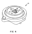
- a diffused light reflectance readhead 10 is designed with one or more improved light emitting diodes (LEDs) 12 to reflect light 13 off of a reagent test pad reacted with an analyte 14 .
- the LEDs 12 are pulsed on and off using a constant-current pulsed direct current (DC) power supply (not shown). Pulsing the LEDs 12 minimizes heating as well as associated light 13 intensity and wavelength variation.
- DC direct current
- the LED's 12 curved outer surface in its epoxy casing acts as a lens to some degree.
- the present invention takes advantage of the lensing effect by relocating a light emitting semiconductor die 15 (also commonly known as a "chip") inside the LED 12 to a position approximately at the focal point of the curved outer surface.
- a light emitting semiconductor die 15 also commonly known as a "chip”
- Computer modeling and experimental results were used to obtain an optimum tip-to-die distance ( ⁇ ) of 0.170 ⁇ 0.01 inch for this configuration. Note that other distances for ⁇ can be used but are not considered optimal.
- the present invention reduces the light's 13 resultant illumination spot size on the reagent strip 14 .
- a significant portion of the spot size is less than 0.100 inch in diameter at a distance of 0.150 inch beyond the readhead surface. Because the spot size is reduced the need for a focusing lens is eliminated, thus saving its cost.
- a standard T1 LED for example, has a die-to-tip distance ( ⁇ ) of about 0.100 inch. As ⁇ is increased to approach the focal point of the standard T1 LED the light 13 out from the standard LED becomes more collimated. This tends to produce a smaller spot for an equivalent aperture size.
- the smaller spot size and increased collimation has the advantage of making the readhead less sensitive to positioning of the die 15 within the LEDs 12 . Thus, if the LEDs' 12 die 15 is not placed at the center of the LEDs 12 , the output spot position will be shifted a smaller amount in proportion to the die 15 centering error.
- each LED 12 and each illumination aperture 16 associated with that LED 12 must illuminate a spot of the proper size and intensity.
- the significant portion of the spot size should be less than the pad size to reduce generation of stray light. Generally, greater intensity is desirable because signal strength is increased.
- the LEDs 12 have their sides coated with a light absorbing material to further reduce stray light as is known in the arts. The total effect is approximately a 200-300 percent signal improvement over prior LEDs used in readheads.
- ⁇ is equal to 5 degrees
- the large reduction of specular reflection enabled the LEDs 12 and the light sensor 24 to be located in closer proximity to one another than currently possible, thereby reducing the size of the reflectance photometer.
- the sample to detector distance is approximately 0.4 inch, which is one half of some current readheads, thus providing an increase in signal by about a factor of 4.
- the reduction in spectral reflection enabled the viewing area of the light sensor 24 to be opened up, engendering significant improvements in the readhead's 10 sensitivity to variations in reagent strip 14 height variations.
- angle ⁇ has been found to approximately range between 3 degrees and 8 degrees for reagent test strips 14 reacted with blood containing glucose, however, the range should be similar for other analytes as well.
- angle ⁇ becomes less than 3 degrees the reduction in specular reflection becomes relatively small.
- angle ⁇ becomes greater than 8 degrees then desirable diffuse color reflection is reduced, along with undesirable specular reflection, to the point that significant signal loss begins to occur. Note that if ⁇ is less than 3 degrees or greater than 8 degrees the readhead 10 will still perform, however, not optimally.
- each step's top side 30 and vertical side 32 are approximately of equal length and positioned at a 90 degree angle to each other. It has been found that the length of each step side 30,32 works best to eliminate stray light and pass desirable diffuse reflected light 13 when sized between 0.010 inch and 0.030 inch.
- step 28 size is practically limited to something smaller than would extend into the LEDs 12 or the illumination apertures 16 .
- the length of each step side 30,32 was chosen to be 0.020 inch.
- the number of steps 28 is not fixed but desirably there are a sufficient number of steps 28 to extend the entire length of the staircase baffle 26 .
- the total length of the staircase baffle 26 is a function of geometry. Manufacturing limitations set a minimum separation distance between the LEDs 12 and the light sensor 24 . Knowing the minimum separation distance and the distance from the LEDs 12 to the reagent test pad 14 along with the fact that the steps 28 are at an angle ⁇ of 45 degrees allows a simple calculation of the distance the steps 28 must cover. Thus, in one embodiment there are 7 individual steps 28 as illustrated in Figures 1 , 2 and 4 .
- the steps 28 are positioned on a side of staircase baffle 26 closest to the LEDs 12 . This is because it has been found that most of the stray light enters an aperture leading to the sensor 24 on the close side and that having the steps there filters out most of stray light.
- steps 28 for the staircase baffle 26 A key advantage to the use of steps 28 for the staircase baffle 26 is the ease in manufacture over the prior art. Steps 28 can easy be formed from a mold while prior art threads are not so easily formed in the readhead 10 material.
- Devices that can be employed as the sensor 24 include charge coupled devices (CCDs), photocells and photodiodes.
- CCDs charge coupled devices
- a OPT101W-R sensor from Burr-Brown, International Airport Industrial Park, 6730 South Arlington Boulevard., Arlington, Arizona 85706, is employed as the light sensor 24 .
- the sensor 24 has an electrical response that is proportional to the reflected light 13 received.
- the electrical response is interpreted by processing electronics (not shown).
- the processing electronics convert the analog electrical response of the sensor 24 into digital data.
- the processing electronics also include a microprocessor (not shown) which stores and utilizes the digital data to calculate contrast variations indicated by the sensor 24 .
- the change in color is used to determine a concentration of glucose in a blood sample.
Applications Claiming Priority (2)
| Application Number | Priority Date | Filing Date | Title |
|---|---|---|---|
| US08/523,272 US5611999A (en) | 1995-09-05 | 1995-09-05 | Diffused light reflectance readhead |
| US523272 | 1995-09-05 |
Publications (1)
| Publication Number | Publication Date |
|---|---|
| EP0762112A1 true EP0762112A1 (fr) | 1997-03-12 |
Family
ID=24084332
Family Applications (1)
| Application Number | Title | Priority Date | Filing Date |
|---|---|---|---|
| EP96114068A Withdrawn EP0762112A1 (fr) | 1995-09-05 | 1996-09-03 | Tête de lecture pour la réflexion de lumière diffuse |
Country Status (5)
| Country | Link |
|---|---|
| US (1) | US5611999A (fr) |
| EP (1) | EP0762112A1 (fr) |
| JP (1) | JP3787194B2 (fr) |
| AU (1) | AU685711B2 (fr) |
| CA (1) | CA2184310C (fr) |
Cited By (6)
| Publication number | Priority date | Publication date | Assignee | Title |
|---|---|---|---|---|
| EP0806651A2 (fr) * | 1996-05-09 | 1997-11-12 | Bayer Corporation | Spectroscope de réflectance avec tête de lecture pour réduire au minimum les rayons de lumière réfléchis une seule fois. |
| EP0952440A2 (fr) * | 1998-04-20 | 1999-10-27 | Bayer Corporation | Tête photométrique de lecture avec plaque de formation de faisceau |
| WO2006065899A1 (fr) * | 2004-12-13 | 2006-06-22 | Bayer Healthcare Llc | Procede pour etablir une distinction entre des solutions de sang et de controle contenant un analyte commun |
| US8002965B2 (en) | 2005-04-08 | 2011-08-23 | Bayer Healthcare Llc | Oxidizable species as an internal reference in control solutions for biosensors |
| US8337691B2 (en) | 2007-12-10 | 2012-12-25 | Bayer Healthcare Llc | Control markers for auto-detection of control solution and method of use |
| US8696880B2 (en) | 2004-02-06 | 2014-04-15 | Bayer Healthcare Llc | Oxidizable species as an internal reference for biosensors and method of use |
Families Citing this family (44)
| Publication number | Priority date | Publication date | Assignee | Title |
|---|---|---|---|---|
| US5995236A (en) * | 1998-04-13 | 1999-11-30 | Mit Development Corporation | Blood fluid characteristics analysis instrument |
| US6652807B1 (en) * | 2000-07-13 | 2003-11-25 | Oceanit Test Systems, Inc. | Cigua-dart method for detection of ciguatera toxins |
| US7776608B2 (en) * | 2001-07-09 | 2010-08-17 | Bayer Healthcare Llc | Volume meter testing device and method of use |
| CA2419200C (fr) | 2002-03-05 | 2015-06-30 | Bayer Healthcare Llc | Appareil de prelevement de fluide muni d'une lancette integree et d'une zone de reaction |
| US7604981B1 (en) * | 2002-03-08 | 2009-10-20 | The Board Of Trustees Of The Leland Stanford Junior University | Excitable target marker detection |
| NZ526334A (en) | 2002-06-25 | 2003-10-31 | Bayer Healthcare Llc | Sensor with integrated lancet for monitoring blood by colorometric or electrochemical test method |
| US7604775B2 (en) * | 2002-08-12 | 2009-10-20 | Bayer Healthcare Llc | Fluid collecting and monitoring device |
| EP1936356A1 (fr) | 2002-10-29 | 2008-06-25 | Bayer HealthCare LLC | Tête de lecture à réflectance diffuse |
| CA2446368C (fr) * | 2002-10-29 | 2014-10-14 | Bayer Healthcare Llc | Tete de lecture a reflexion diffuse |
| US8153081B2 (en) | 2003-05-29 | 2012-04-10 | Bayer Healthcare Llc | Test sensor and method for manufacturing the same |
| DK1484601T3 (da) * | 2003-06-04 | 2009-06-08 | Inverness Medical Switzerland | Optisk indretning til et assay-aflæsningsapparat |
| US20040248312A1 (en) * | 2003-06-06 | 2004-12-09 | Bayer Healthcare, Llc | Sensor with integrated lancet |
| US20040267299A1 (en) * | 2003-06-30 | 2004-12-30 | Kuriger Rex J. | Lancing devices and methods of using the same |
| US7543481B2 (en) * | 2004-02-06 | 2009-06-09 | Bayer Healthcare, Llc | Fluid testing sensor having vents for directing fluid flow |
| ATE490729T1 (de) * | 2004-02-06 | 2010-12-15 | Bayer Healthcare Llc | Gerät zur messung eines analyten in einer körperflüssigkeit |
| JP2008503724A (ja) * | 2004-06-17 | 2008-02-07 | バイエル・ヘルスケア・エルエルシー | 同軸拡散反射読取ヘッド |
| WO2006014410A1 (fr) * | 2004-07-02 | 2006-02-09 | Bayer Healthcare Llc | Capteur de test de guide lumineux servant à la détermination d’un analyte dans un échantillon de fluide et procédés de fabrication dudit capteur |
| US20060066850A1 (en) * | 2004-09-29 | 2006-03-30 | Fuji Photo Film Co., Ltd. | Light measuring device, biochemical analyzer, biochemical analysis method, and spectrophotometer |
| US20060092410A1 (en) * | 2004-10-28 | 2006-05-04 | Owens-Brockway Glass Container Inc. | Container inspection by directly focusing a light emitting die element onto the container |
| EP2063252B1 (fr) | 2004-12-13 | 2016-06-22 | Ascensia Diabetes Care Holdings AG | Système de spectroscopie à transmission à utiliser pour la détermination des analytes dans un fluide corporel |
| RU2007127254A (ru) * | 2004-12-17 | 2009-01-27 | Байер Хелткэр Ллк (Us) | Устройство с дисплеем, отображающим тенденцию измерения |
| WO2006076668A1 (fr) | 2005-01-14 | 2006-07-20 | Bayer Healthcare Llc | Dispositif et procede d'affichage et d'impression d'une concentration d'analyte dans un echantillon de fluide |
| US20060281187A1 (en) | 2005-06-13 | 2006-12-14 | Rosedale Medical, Inc. | Analyte detection devices and methods with hematocrit/volume correction and feedback control |
| EP3461406A1 (fr) | 2005-09-30 | 2019-04-03 | Intuity Medical, Inc. | Cartouche d'échantillonnage et d'analyse de fluide corporel multi-sites |
| WO2007133456A2 (fr) * | 2006-05-08 | 2007-11-22 | Bayer Healthcare Llc | Capteur d'analyse comprenant une protection contre un remplissage insuffisant |
| US7797987B2 (en) * | 2006-10-11 | 2010-09-21 | Bayer Healthcare Llc | Test sensor with a side vent and method of making the same |
| US20080105024A1 (en) * | 2006-11-07 | 2008-05-08 | Bayer Healthcare Llc | Method of making an auto-calibrating test sensor |
| EP2101634A1 (fr) * | 2006-12-13 | 2009-09-23 | Bayer Healthcare, LLC | Biocapteur avec informations codées et procédé de fabrication de celui-ci |
| US20080248581A1 (en) * | 2007-04-06 | 2008-10-09 | Bayer Healthcare Llc | Method for performing correction of blood glucose assay bias using blood hemoglobin concentration |
| BRPI0814144A2 (pt) * | 2007-08-06 | 2015-02-03 | Bayer Healthcare Llc | Sistema e método para calibração automática |
| US8241488B2 (en) | 2007-11-06 | 2012-08-14 | Bayer Healthcare Llc | Auto-calibrating test sensors |
| US20090205399A1 (en) * | 2008-02-15 | 2009-08-20 | Bayer Healthcare, Llc | Auto-calibrating test sensors |
| JP5816080B2 (ja) | 2008-05-30 | 2015-11-17 | インテュイティ メディカル インコーポレイテッド | 体液採取装置及び採取部位インターフェイス |
| US20090305317A1 (en) * | 2008-06-05 | 2009-12-10 | Brauer Jacob S | User interface for testing device |
| JP5642066B2 (ja) | 2008-06-06 | 2014-12-17 | インテュイティ メディカル インコーポレイテッド | 体液の試料内に含まれている検体の存在または濃度を決定する検定を行う方法および装置 |
| US20110122411A1 (en) * | 2008-06-20 | 2011-05-26 | 77 Elektronika Mvszeripari Kft. | Optical measuring unit and method for carrying out a reflective measurement |
| US8424763B2 (en) * | 2008-10-07 | 2013-04-23 | Bayer Healthcare Llc | Method of forming an auto-calibration circuit or label |
| WO2010048277A2 (fr) | 2008-10-21 | 2010-04-29 | Bayer Healthcare Llc | Procédé d'auto-étalonnage optique |
| CN102227627B (zh) | 2008-12-18 | 2014-10-08 | 拜尔健康护理有限责任公司 | 用于测定测试传感器温度的方法和组件 |
| JP5290058B2 (ja) | 2009-06-05 | 2013-09-18 | テルモ株式会社 | 成分測定装置 |
| CA2782047C (fr) | 2009-11-30 | 2019-10-29 | Intuity Medical, Inc. | Dispositif et procede de fourniture de materiau d'etalonnage |
| EP3407064B1 (fr) | 2011-08-03 | 2020-04-22 | Intuity Medical, Inc. | Dispositifs de prélèvement de fluide corporel |
| WO2014115666A1 (fr) | 2013-01-23 | 2014-07-31 | テルモ株式会社 | Procédé d'étalonnage, système d'étalonnage et dispositif de mesure de composant de fluide corporel étalonné au moyen dudit procédé |
| JP6313224B2 (ja) | 2013-01-23 | 2018-04-18 | テルモ株式会社 | 校正方法、装置、及びプログラム、並びにこの方法を用いて校正された体液成分測定装置 |
Citations (7)
| Publication number | Priority date | Publication date | Assignee | Title |
|---|---|---|---|---|
| DE2039348A1 (de) * | 1970-08-07 | 1972-02-10 | Freudenberg Carl Fa | Verfahren zur Bestimmung der Wolkigkeit diffus reflektierender Proben |
| EP0110262A2 (fr) * | 1982-11-29 | 1984-06-13 | Miles Laboratories, Inc. | Tête de lecture optique |
| EP0125340A2 (fr) * | 1982-11-01 | 1984-11-21 | Miles Inc. | Dispositif pour la mesure de lumière reflétée non spéculaire |
| US4552458A (en) * | 1983-10-11 | 1985-11-12 | Eastman Kodak Company | Compact reflectometer |
| DE3720166A1 (de) * | 1987-06-16 | 1988-12-29 | Vysoka Skola Chem Tech | Photometrische zelle zum auswerten der intensitaet der verfaerbung von reagenzstreifen |
| DE8907969U1 (fr) * | 1989-06-29 | 1989-09-14 | Lre Relais + Elektronik Gmbh, 8000 Muenchen, De | |
| US5518689A (en) * | 1995-09-05 | 1996-05-21 | Bayer Corporation | Diffused light reflectance readhead |
Family Cites Families (4)
| Publication number | Priority date | Publication date | Assignee | Title |
|---|---|---|---|---|
| JPH01253634A (ja) * | 1988-04-01 | 1989-10-09 | Fuji Photo Film Co Ltd | 反射濃度測定装置 |
| US4950905A (en) * | 1989-02-06 | 1990-08-21 | Xerox Corporation | Colored toner optical developability sensor with improved sensing latitude |
| US5139339A (en) * | 1989-12-26 | 1992-08-18 | Xerox Corporation | Media discriminating and media presence sensor |
| US5350697A (en) * | 1990-08-28 | 1994-09-27 | Akzo N.V. | Scattered light detection apparatus |
-
1995
- 1995-09-05 US US08/523,272 patent/US5611999A/en not_active Expired - Lifetime
-
1996
- 1996-08-28 CA CA002184310A patent/CA2184310C/fr not_active Expired - Fee Related
- 1996-09-03 JP JP23240196A patent/JP3787194B2/ja not_active Expired - Lifetime
- 1996-09-03 EP EP96114068A patent/EP0762112A1/fr not_active Withdrawn
- 1996-09-04 AU AU64455/96A patent/AU685711B2/en not_active Ceased
Patent Citations (7)
| Publication number | Priority date | Publication date | Assignee | Title |
|---|---|---|---|---|
| DE2039348A1 (de) * | 1970-08-07 | 1972-02-10 | Freudenberg Carl Fa | Verfahren zur Bestimmung der Wolkigkeit diffus reflektierender Proben |
| EP0125340A2 (fr) * | 1982-11-01 | 1984-11-21 | Miles Inc. | Dispositif pour la mesure de lumière reflétée non spéculaire |
| EP0110262A2 (fr) * | 1982-11-29 | 1984-06-13 | Miles Laboratories, Inc. | Tête de lecture optique |
| US4552458A (en) * | 1983-10-11 | 1985-11-12 | Eastman Kodak Company | Compact reflectometer |
| DE3720166A1 (de) * | 1987-06-16 | 1988-12-29 | Vysoka Skola Chem Tech | Photometrische zelle zum auswerten der intensitaet der verfaerbung von reagenzstreifen |
| DE8907969U1 (fr) * | 1989-06-29 | 1989-09-14 | Lre Relais + Elektronik Gmbh, 8000 Muenchen, De | |
| US5518689A (en) * | 1995-09-05 | 1996-05-21 | Bayer Corporation | Diffused light reflectance readhead |
Cited By (19)
| Publication number | Priority date | Publication date | Assignee | Title |
|---|---|---|---|---|
| EP0806651A3 (fr) * | 1996-05-09 | 1998-11-11 | Bayer Corporation | Spectroscope de réflectance avec tête de lecture pour réduire au minimum les rayons de lumière réfléchis une seule fois. |
| EP0806651A2 (fr) * | 1996-05-09 | 1997-11-12 | Bayer Corporation | Spectroscope de réflectance avec tête de lecture pour réduire au minimum les rayons de lumière réfléchis une seule fois. |
| EP0952440A2 (fr) * | 1998-04-20 | 1999-10-27 | Bayer Corporation | Tête photométrique de lecture avec plaque de formation de faisceau |
| US9410917B2 (en) | 2004-02-06 | 2016-08-09 | Ascensia Diabetes Care Holdings Ag | Method of using a biosensor |
| US10067082B2 (en) | 2004-02-06 | 2018-09-04 | Ascensia Diabetes Care Holdings Ag | Biosensor for determining an analyte concentration |
| US8696880B2 (en) | 2004-02-06 | 2014-04-15 | Bayer Healthcare Llc | Oxidizable species as an internal reference for biosensors and method of use |
| WO2006065899A1 (fr) * | 2004-12-13 | 2006-06-22 | Bayer Healthcare Llc | Procede pour etablir une distinction entre des solutions de sang et de controle contenant un analyte commun |
| US8102517B2 (en) | 2004-12-13 | 2012-01-24 | Bayer Healthcare, Llc | Method of differentiating between blood and control solutions containing a common analyte |
| US8416398B2 (en) | 2004-12-13 | 2013-04-09 | Bayer Healthcare, Llc | Method of differentiating between blood and control solutions containing a common analyte |
| US8681324B2 (en) | 2004-12-13 | 2014-03-25 | Bayer Healthcare, Llc | Method of differentiating between blood and control solutions containing a common analyte |
| US8002965B2 (en) | 2005-04-08 | 2011-08-23 | Bayer Healthcare Llc | Oxidizable species as an internal reference in control solutions for biosensors |
| US9244078B2 (en) | 2005-04-08 | 2016-01-26 | Bayer Healthcare Llc | Oxidizable species as an internal reference in control solutions for biosensors |
| US8702926B2 (en) | 2005-04-08 | 2014-04-22 | Bayer Healthcare Llc | Oxidizable species as an internal reference in control solutions for biosensors |
| US9766198B2 (en) | 2005-04-08 | 2017-09-19 | Ascensia Diabetes Care Holdings Ag | Oxidizable species as an internal reference in control solutions for biosensors |
| US8716024B2 (en) | 2007-12-10 | 2014-05-06 | Bayer Healthcare Llc | Control solution for use in testing an electrochemical system |
| US8871517B2 (en) | 2007-12-10 | 2014-10-28 | Bayer Healthcare Llc | Method of using a control solution and preparing for testing using the same |
| US9933385B2 (en) | 2007-12-10 | 2018-04-03 | Ascensia Diabetes Care Holdings Ag | Method of using an electrochemical test sensor |
| US8337691B2 (en) | 2007-12-10 | 2012-12-25 | Bayer Healthcare Llc | Control markers for auto-detection of control solution and method of use |
| US10690614B2 (en) | 2007-12-10 | 2020-06-23 | Ascensia Diabetes Care Holdings Ag | Method of using an electrochemical test sensor |
Also Published As
| Publication number | Publication date |
|---|---|
| AU6445596A (en) | 1997-03-13 |
| CA2184310C (fr) | 1999-08-24 |
| JP3787194B2 (ja) | 2006-06-21 |
| AU685711B2 (en) | 1998-01-22 |
| CA2184310A1 (fr) | 1997-03-06 |
| US5611999A (en) | 1997-03-18 |
| JPH09145615A (ja) | 1997-06-06 |
Similar Documents
| Publication | Publication Date | Title |
|---|---|---|
| US5518689A (en) | Diffused light reflectance readhead | |
| US5611999A (en) | Diffused light reflectance readhead | |
| US4420566A (en) | Method and apparatus for detecting sample fluid on an analysis slide | |
| JP3994143B2 (ja) | 血液分析器のための検体の迅速な分光光度法の予備検査鑑別方法及び装置 | |
| JP2916637B2 (ja) | 拡散分光反射率の測定装置 | |
| US5986754A (en) | Medical diagnostic apparatus using a Fresnel reflector | |
| US5701181A (en) | Fiber optic diffuse light reflectance sensor utilized in the detection of occult blood | |
| US7339673B2 (en) | Miniature optical readhead for optical diagnostic device | |
| JP2004317487A (ja) | 体液中の分析対象物の測定に使用するための多重波長読み取りヘッド | |
| US6522398B2 (en) | Apparatus for measuring hematocrit | |
| CA2597295C (fr) | Methode pour l'analyse d'un echantillon d'un element de test et systeme d'analyse | |
| JPH10267833A (ja) | 測光診断計の読み取りヘッド | |
| EP0087466B1 (fr) | Procede et dispositif de detection de fluide d'echantillon | |
| AU676270B1 (en) | Diffused light reflectance readhead | |
| EP0185285A2 (fr) | Appareil de mesure de niveau du liquide | |
| JPS59109844A (ja) | 反射光測定装置 | |
| EP0125340B1 (fr) | Dispositif pour la mesure de lumière reflétée non spéculaire | |
| CN116472449A (zh) | 用于侧流免疫学检测的tricorder反射计 | |
| US20190162722A1 (en) | Detection Apparatus and Detection Method | |
| JPS58501441A (ja) | サンプル流体を検知する方法及び装置 |
Legal Events
| Date | Code | Title | Description |
|---|---|---|---|
| PUAI | Public reference made under article 153(3) epc to a published international application that has entered the european phase |
Free format text: ORIGINAL CODE: 0009012 |
|
| AK | Designated contracting states |
Kind code of ref document: A1 Designated state(s): DE FR GB IT |
|
| RAP1 | Party data changed (applicant data changed or rights of an application transferred) |
Owner name: BAYER CORPORATION |
|
| 17P | Request for examination filed |
Effective date: 19970912 |
|
| 17Q | First examination report despatched |
Effective date: 20010912 |
|
| STAA | Information on the status of an ep patent application or granted ep patent |
Free format text: STATUS: THE APPLICATION HAS BEEN WITHDRAWN |
|
| 18W | Application withdrawn |
Effective date: 20021129 |