EP0762028B1 - Druckempfindliches Ventil - Google Patents
Druckempfindliches Ventil Download PDFInfo
- Publication number
- EP0762028B1 EP0762028B1 EP96202433A EP96202433A EP0762028B1 EP 0762028 B1 EP0762028 B1 EP 0762028B1 EP 96202433 A EP96202433 A EP 96202433A EP 96202433 A EP96202433 A EP 96202433A EP 0762028 B1 EP0762028 B1 EP 0762028B1
- Authority
- EP
- European Patent Office
- Prior art keywords
- fluid
- reverse buckling
- piston
- inlet port
- pressure sensitive
- Prior art date
- Legal status (The legal status is an assumption and is not a legal conclusion. Google has not performed a legal analysis and makes no representation as to the accuracy of the status listed.)
- Expired - Lifetime
Links
- 230000002441 reversible effect Effects 0.000 claims description 66
- 239000012528 membrane Substances 0.000 claims description 64
- 238000007789 sealing Methods 0.000 claims description 62
- 239000012530 fluid Substances 0.000 claims description 57
- 230000000717 retained effect Effects 0.000 claims description 5
- 238000004891 communication Methods 0.000 claims description 3
- 239000007787 solid Substances 0.000 description 6
- 230000009172 bursting Effects 0.000 description 4
- 239000002184 metal Substances 0.000 description 4
- 239000000463 material Substances 0.000 description 3
- 238000005260 corrosion Methods 0.000 description 2
- 230000007797 corrosion Effects 0.000 description 2
- 238000005516 engineering process Methods 0.000 description 2
- 238000004519 manufacturing process Methods 0.000 description 2
- 230000015572 biosynthetic process Effects 0.000 description 1
- 235000014171 carbonated beverage Nutrition 0.000 description 1
- 238000012993 chemical processing Methods 0.000 description 1
- 230000006835 compression Effects 0.000 description 1
- 238000007906 compression Methods 0.000 description 1
- 230000001419 dependent effect Effects 0.000 description 1
- 239000002360 explosive Substances 0.000 description 1
- 229910052500 inorganic mineral Inorganic materials 0.000 description 1
- 238000007689 inspection Methods 0.000 description 1
- 230000007774 longterm Effects 0.000 description 1
- 230000013011 mating Effects 0.000 description 1
- 238000000034 method Methods 0.000 description 1
- 239000011707 mineral Substances 0.000 description 1
- 230000002035 prolonged effect Effects 0.000 description 1
- 230000003014 reinforcing effect Effects 0.000 description 1
- 238000011179 visual inspection Methods 0.000 description 1
Images
Classifications
-
- F—MECHANICAL ENGINEERING; LIGHTING; HEATING; WEAPONS; BLASTING
- F16—ENGINEERING ELEMENTS AND UNITS; GENERAL MEASURES FOR PRODUCING AND MAINTAINING EFFECTIVE FUNCTIONING OF MACHINES OR INSTALLATIONS; THERMAL INSULATION IN GENERAL
- F16K—VALVES; TAPS; COCKS; ACTUATING-FLOATS; DEVICES FOR VENTING OR AERATING
- F16K17/00—Safety valves; Equalising valves, e.g. pressure relief valves
- F16K17/02—Safety valves; Equalising valves, e.g. pressure relief valves opening on surplus pressure on one side; closing on insufficient pressure on one side
- F16K17/04—Safety valves; Equalising valves, e.g. pressure relief valves opening on surplus pressure on one side; closing on insufficient pressure on one side spring-loaded
- F16K17/0493—Safety valves; Equalising valves, e.g. pressure relief valves opening on surplus pressure on one side; closing on insufficient pressure on one side spring-loaded with a spring other than a helicoidal spring
-
- F—MECHANICAL ENGINEERING; LIGHTING; HEATING; WEAPONS; BLASTING
- F16—ENGINEERING ELEMENTS AND UNITS; GENERAL MEASURES FOR PRODUCING AND MAINTAINING EFFECTIVE FUNCTIONING OF MACHINES OR INSTALLATIONS; THERMAL INSULATION IN GENERAL
- F16K—VALVES; TAPS; COCKS; ACTUATING-FLOATS; DEVICES FOR VENTING OR AERATING
- F16K31/00—Actuating devices; Operating means; Releasing devices
- F16K31/44—Mechanical actuating means
- F16K31/56—Mechanical actuating means without stable intermediate position, e.g. with snap action
- F16K31/566—Mechanical actuating means without stable intermediate position, e.g. with snap action using a bistable spring device arranged symmetrically around the actuating stem
-
- Y—GENERAL TAGGING OF NEW TECHNOLOGICAL DEVELOPMENTS; GENERAL TAGGING OF CROSS-SECTIONAL TECHNOLOGIES SPANNING OVER SEVERAL SECTIONS OF THE IPC; TECHNICAL SUBJECTS COVERED BY FORMER USPC CROSS-REFERENCE ART COLLECTIONS [XRACs] AND DIGESTS
- Y10—TECHNICAL SUBJECTS COVERED BY FORMER USPC
- Y10T—TECHNICAL SUBJECTS COVERED BY FORMER US CLASSIFICATION
- Y10T137/00—Fluid handling
- Y10T137/7722—Line condition change responsive valves
- Y10T137/7723—Safety cut-off requiring reset
- Y10T137/7728—High pressure cut-off
-
- Y—GENERAL TAGGING OF NEW TECHNOLOGICAL DEVELOPMENTS; GENERAL TAGGING OF CROSS-SECTIONAL TECHNOLOGIES SPANNING OVER SEVERAL SECTIONS OF THE IPC; TECHNICAL SUBJECTS COVERED BY FORMER USPC CROSS-REFERENCE ART COLLECTIONS [XRACs] AND DIGESTS
- Y10—TECHNICAL SUBJECTS COVERED BY FORMER USPC
- Y10T—TECHNICAL SUBJECTS COVERED BY FORMER US CLASSIFICATION
- Y10T137/00—Fluid handling
- Y10T137/7722—Line condition change responsive valves
- Y10T137/7734—Fluid opened valve requiring reset
Definitions
- This invention relates to pressure sensitive valves which open or shut, under set limiting or emergency conditions, by the action of a reverse buckling member within the body of the valve.
- a pressure sensitive valve comprising the features as defined in claim 1.
- Pressure sensitive valves may be used in any pressurised system including, but not limited to, a car braking system, a chemical processing plant, an oil or gas production facility, a carbonated beverage machine, a power station or a missile/aircraft system.
- a car braking system a chemical processing plant
- an oil or gas production facility a carbonated beverage machine
- a power station a missile/aircraft system.
- Pressure sensitive valves according to the present invention may be used as pressure relief valves or as pressure shut off valves in order to protect equipment from being overpressurised.
- a pressure relief valve vents excess pressure using a normally closed valve while a pressure shut off valve serves to isolate equipment from a high pressure source using a normally open valve.
- pressure sensitive valves of the present invention may be used where a seal is required to be activated (opened or closed) by a specific or set pressure.
- the description hereinafter refers primarily to pressure relief valves and pressure shut off valves but is not limited thereto.
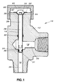
- the pressure relief valve 10 comprises a valve body 12 defining a bore 14, an inlet port 16 and an outlet port 18.
- the inlet port 16 is in fluid communication with the outlet port 18 when the valve 10 is open and defines a fluid flow path 20.
- the fluid flow path 20 is in communication with the bore 14.
- a reverse buckling member in the form of a reverse buckling membrane 22 extends across the mouth 24 of the bore 14 distal the fluid flow path 20 and the rim of the membrane 22 is fixed to the valve body 12 in any conventional manner (not shown).
- the reverse buckling membrane 22 is adapted to reverse or invert its conformation when a set pressure has been exceeded.
- a piston 26 is slidably moveable in the bore 14, as will be described in greater detail hereinafter.
- the end 28 of the piston 26 distal the fluid flow path 20 is in operative association with the reverse buckling membrane 22.
- the end 28 is fixedly engaged to the reverse buckling membrane 22 by means of a screw-threaded projection (not shown) extending from the end 28 through an aperture (shown only in Figure 4A-C as 352, 452, 552) provided in the reverse buckling membrane 22 and fixed in place by a nut 30 or the like.
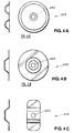
- the reverse buckling member may take a number of forms which either fully or partially extend across the mouth 24 of the bore 14.
- the reverse buckling member takes the form of a reverse buckling membrane 22 which is substantially disc-like in shape and which extends fully across and covers the mouth 24 of the bore 14.
- the reverse buckling membrane 22 may be substantially strap-like in shape ( Figure 4c) extending fully across but not fully covering the mouth 24 of the bore 14.
- the reverse buckling member may take the form of a strap or semi-disc (not shown) which extends partially across the mouth 24 of the bore 14 between the body 12 and the piston 26.
- the reverse buckling member is adapted to reverse or invert its conformation when a set pressure has been exceeded.
- a sealing ring 32 is located in the bore 14 and is adapted and arranged to permit axial movement of the piston 26 in the bore 14 and to prevent fluid in the fluid flow path 20 from contacting the reverse buckling membrane 22.
- a second sealing ring (not shown) may be located in the bore 14 adjacent the mouth 24, to prevent ingress of grit and the like from the surrounding atmosphere into the bore 14.
- the end 34 of the piston 26 distal the reverse buckling membrane 22 is sealingly engaged with the inlet port 16 by means of a sealing annulus 36.
- the pressure relief valve 10 is a normally closed pressure relief valve 10 so that, in the normally closed position, the sealing annulus 36 is in sealing engagement with the inlet port 16 and fluid is retained in the inlet port 16.
- the sealing annulus 36 acts as the means for sealing the reverse buckling membrane 22 from the fluid flow path 20 when the valve 10 is in the normally closed position and the sealing ring 32 acts as the means for sealing the reverse buckling membrane 22 from the fluid flow path 20 when the valve 10 is in the open position.
- a quantity of fluid (not shown) may be located in the outlet port 18. Under such conditions, the sealing ring 32 serves to seal the reverse buckling membrane 22 from the fluid located in the outlet port 18.
- a screwed plug 46 defining a chamber 47 is provided, which plug 46 enables access to the reverse buckling membrane 22 for visual inspection and replacement if necessary.
- the predetermined or set force on the piston 26 causes the reverse buckling membrane 22 to invert or reverse its conformation so that it moves from a normal position 38 (shown in solid outline) to an emergency position 40 (shown in dotted outline).
- This rearward movement (or retraction) of the piston 26 relative to the bore 14 causes the piston 26/sealing annulus 36 to slide out of sealing engagement with the inlet port 16 which, in turn, causes fluid to move from the inlet port 16 through to the outlet port 18.
- the chamber 47 of the plug 46 is shaped and dimensioned to permit buckling of the membrane 22 to the emergency position 40.
- FIG. 1 a pressure relief valve generally indicated as 110, which is a normally closed pressure relief valve.
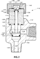
- valve body 112 includes a screw-threaded bonnet 148 which, in the first embodiment, is a unitary part of the valve body 12.
- the end 134 of the piston 126 is shaped to form a head 142 which is shaped and dimensioned for sealing engagement with the inlet port 116 in the normally closed position.
- a sealing annulus 136 is provided in an annular groove 137 of the head 142.
- a first sealing ring 132 is provided in an annular groove in the bonnet 148 distal the reverse buckling membrane 122.
- a second sealing ring 150 is provided in an annular groove 151 of the bonnet 148 adjacent the reverse buckling membrane 122.
- the sealing annulus 136 In use, in the normally closed position, the sealing annulus 136 is in sealing engagement with the inlet port 116 and fluid is retained in the inlet port 116. Thus, the sealing annulus 136 acts as the means for sealing the reverse buckling membrane 122 from the fluid flow path 120 when the valve 110 is in the normally closed position. It will be appreciated that, in the normally closed position, a quantity of fluid (not shown) may be located in the outlet port 118. Under such conditions, the sealing ring 132 serves to seal the reverse buckling membrane 122 from the fluid located in the outlet port 118.
- the piston head 142/piston 126 When the set pressure has been exceeded, the piston head 142/piston 126 is forced rearwardly into the bore 114, thereby causing the reverse buckling membrane 122 to invert so that it moves from the normal position 138 (shown in solid outline) to the emergency position 140 (shown in dotted outline).
- This rearward movement of the head 142/piston 126 relative to the bore 114 causes the head 142 to slide out of sealing engagement with the inlet port 116 which, in turn, permits fluid to move from the inlet port 116 through to the outlet port 118.
- the sealing ring 132 acts as the means for sealing the reverse buckling membrane 122 from the fluid flow path 120 when the valve 110 is in the open position.
- the second sealing ring 150 serves to prevent dirt or grit from entering into the bore 114.
- the plug 146 is shaped to engage against the rim of the membrane 122, so as to fix the membrane 122 between the plug 146 and the bonnet 148 of the valve body 112.
- chamber 147 of the plug 146 must be shaped and dimensioned to permit buckling of membrane 122 to the emergency position 140.
- a separable bonnet 148 permits access, if required, to the head 142 of the piston 126, if repair or inspection is desired.
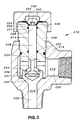
- FIG. 3 there is illustrated a third embodiment of a pressure sensitive valve generally indicated as 210, which is a normally open pressure shut off valve.
- the end 234 of the piston 226 is shaped to form a head 242 and a mating recess 244 is provided in the inlet port 216.
- the head 242 In use, in a normal or open position, the head 242 is spaced-apart from the recess 244 so that fluid flows from the inlet port 216 past the head 242 and out the outlet port 218.
- the piston 226 When a set pressure has been exceeded, the piston 226 is forced rearwardly into the bore 214, thereby causing the reverse buckling membrane 222 to invert or reverse its conformation from a normal position 238 (shown in solid outline) to an emergency position 240 (shown in dotted outline).
- This rearward movement of the piston 226 into the bore 214 causes the head 242/sealing annulus 236 to come into sealing engagement with the recess 244, thereby preventing fluid flow from the inlet port 216 to the outlet port 218 so as to close the pressure shut off valve 210.
- the sealing means is performed by the sealing annulus 236 when the valve 210 is in the closed position and by the sealing ring 232 when the valve 210 is in the normally open position. It will be appreciated that, when the valve 210 is in the closed position, a quantity of fluid (not shown) may be located in the outlet port 218. Under such conditions, the sealing ring 232 serves to seal the reverse buckling membrane 222 from the fluid located in the outlet port 218. As in the second embodiment, the second sealing ring 250 prevents grit from entering the bore 214.
- sealing ring 32, 132, 232, the second sealing ring 150, 250 and the sealing annulus 36, 136, 236 may each be housed in annular grooves, which grooves are located either in the piston 26/piston head 42 or, alternatively, in the valve body 12, 112, 212.
- sealing ring 32 and the second sealing ring 50 be provided in annular grooves in the valve body 12, whereas it is desirable that the sealing annulus 36 be provided in an annular groove in the piston 26/piston head 142, 242.
- the sealing rings 32, 50 and the sealing annulus 36 should be housed in a manner which provides reliable sealing engagement.
- the membrane 22, 212, 222 can be accessed via the screwed plug 46, 146, 246, it is possible to inspect the membrane 22, 122, 222 at any time and to replace it without shutdown of the pipeline system because the fluid flow path 20, 120, 220 is sealed from the reverse buckling membrane 22, 122, 222.
- This is a particular advantage in the case of pressure sensitive valves 10, 110, 210 with larger fluid flow areas. Since emergency shutdown of a pressure sensitive valve 10, 110, 210 is a safety, rather than a functional, feature, it will be appreciated that such buckling membranes 22, 122, 222 can be in operation for a prolonged period of time.
- a further advantage of buckling membrane, as opposed to pin, pressure sensitive valves lies in membrane's ready ability, as found in experimental practice, to accommodate small batch-to-batch variations in membrane material properties, by very small changes in membrane shape or conformation which do not entail expensive changes in press dies.
- buckling pins, on existing technology need to be heat treated to ensure consistent batch-to-batch performance of what is nominally material of the same specification.
- pressure relief valves of the present invention would be more compact than pressure relief valves incorporating buckling/rupture pins, due to the absence of the elongated buckling/rupturing pin itself.
- the pressure sensitive valves 10, 110, 210 incorporate a fluid isolated reverse buckling membrane 22, 122, 222 in which a set fluid pressure on the actuating means causes the membrane to invert, as opposed to the explosive blow-out of a bursting membrane.
- a fluid isolated reverse buckling membrane 22, 122, 222 in which a set fluid pressure on the actuating means causes the membrane to invert, as opposed to the explosive blow-out of a bursting membrane.
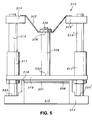
- FIGS. 5 and 6 show a pressure sensitive valve, generally indicated at 310, according to a second aspect of the invention.
- the valve 310 which is a pressure relief valve, includes a valve body 312 having an inlet port 316 and an outlet port 318.
- a guideway comprises a pair of parallel, spaced-apart guide rods 314, 314', each guide rod 314, 314' having a respective shoulder-piece 315, 315' fixed adjacent one end of the guide rod 314, 314' in conventional manner.
- the respective opposite end 323, 323' of each guide rod 314, 314' is fixed in conventional manner to the valve body 312 on opposing sides of the outlet port 318.
- a flange 319 is fixed to the end 334 of the actuating means or piston 326.
- a pair of parallel, spaced-apart sleeves 317, 317' are formed in, and extend substantially perpendicularly from, a face of the flange 319.
- a sealing plug 321 is formed in the opposite face of the flange 319.
- the sealing plug 321 includes a sealing ring 336 and is adapted for sealing engagement with the outlet port 318.
- the piston 326 extends from the flange 319 between, and substantially parallel with, the sleeves 317, 317'.
- the sleeves 317, 317' are, in use, slidably mounted on the respective guide rods 314, 314'.
- the piston 326 is thus axially movable relative to the guide rods 314, 314'.
- a reverse buckling member in the form of a reverse buckling membrane 322 is fixed to and extends between the shoulder-pieces 315, 315' of the guide way.
- the rim of the buckling membrane is fixed to the shoulder-pieces 315, 315' in any suitable conventional manner.
- the reverse buckling member 322 is adapted to reverse or invert its conformation when a set pressure has been exceeded.
- the end 328 of the piston 326 is fixed to the reverse buckling membrane 322 by the nut 330.
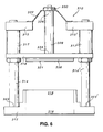
- the pressure relief valve 310 is movable between a normally closed position (as illustrated in Figure 5), in which the sealing plug 321 sealingly engages the outlet port 318 and the reverse buckling membrane 322 is in a normal position, and an open position (as illustrated in Figure 6), in which the sealing plug 321 does not engage the outlet port 318 and the reverse buckling membrane 322 is in an inverted or emergency position.
- a normally closed position as illustrated in Figure 5
- an open position as illustrated in Figure 6
- the sealing plug 321 does not engage the outlet port 318 and the reverse buckling membrane 322 is in an inverted or emergency position.
- valve 310 In use, with the valve 310 in the normally closed position, when fluid (not shown) in the inlet port 316 exceeds a set pressure, the corresponding set force on the piston 326 causes the reverse buckling membrane 322 to invert or reverse its formation so that it moves from the normal position to the inverted or emergency position.
- the piston 326 thus moves upwardly, as viewed in Figures 5 and 6, so that the sealing plug 321 slides out of sealing engagement with the outlet port 318 which, in turn, causes the fluid to move from the inlet port 316 through the outlet port 318 and into the surrounding environment.
Landscapes
- Engineering & Computer Science (AREA)
- General Engineering & Computer Science (AREA)
- Mechanical Engineering (AREA)
- Safety Valves (AREA)
Claims (10)
- Druckempfindliches Ventil (10, 110, 210, 310) umfassend: einen Ventilkörper (12, 112, 212, 312) mit einer Einlaßöffnung (16, 116, 216, 316), einer Auslaßöffnung (18, 118, 218, 318) und einem Fluidströmungsweg (20, 120, 220, 320) zwischen der genannten Einlaß- und Auslaßöffnung (16, 116, 216, 316; 18, 118, 218, 318); ein Stellglied (26, 126, 226, 326), das zwischen einer geschlossenen Position, in der das Stellglied (26, 126, 226, 326) Fluidfluß entlang dem Fluidströmungsweg (20, 120, 220, 320) verhindert, und einer offenen Position bewegbar ist, in der das Stellglied (26, 126, 226, 326) Fluidfluß entlang dem Fluidströmungsweg (20, 120, 220, 320) zuläßt; ein Umkehrbiegeelement (22, 122, 222, 322), das betriebsmäßig mit dem Stellglied (26, 126, 226, 326) verknüpft ist und eine erste Konstellation aufweist, die normalerweise das Stellglied (26, 126, 226, 326) in einer der genannten offenen und geschlossenen Positionen hält, wobei das Stellglied (26, 126, 226, 326) Fluiddruck in dem Ventilkörper (12, 112, 212, 312) ausgesetzt ist, welcher Fluiddruck die Tendenz hat, das Stellglied (26, 126, 226, 326) zu der anderen der genannten offenen und geschlossenen Positionen zu bewegen, wodurch, wenn ein auf das Stellglied (26, 126, 226, 326) einwirkender festgelegter Fluiddruck überschritten wird, das Umkehrbiegeelement (22, 122, 222, 322) sich automatisch in eine zweite Konstellation umdreht, die dem Stellglied (26, 126, 226, 326) ermöglicht, sich unter dem Einfluß des Fluiddrucks in dem Ventilkörper (12, 112, 212, 312) zu der anderen der offenen und geschlossenen Positionen zu bewegen; und Mittel zum Abdichten des Umkehrbiegeelements (22, 122, 222, 322) gegen Fluid in dem Ventil (10, 110, 210, 310) mindestens dann, wenn sich das Umkehrbiegeelement (22, 122, 222, 322) in der ersten Konstellation befindet, wobei das Umkehrbiegeelement (22, 122, 222, 322) eine Umkehrbiegemembran ist, die an ihrem Umfang relativ zum Ventilkörper (12, 112, 212, 312) angebracht ist und zwischen ihrem Umfang betriebsmäßig mit dem Stellglied (26, 126, 226, 326) verknüpft ist.
- Druckempfindliches Ventil (10, 110, 210) nach Anspruch 1, bei dem eine Bohrung (14, 114, 214) in dem Ventilkörper (12, 112, 212) in Kommunikation mit dem Fluidströmungsweg (20, 120, 220) vorgesehen ist, und das Stellglied einen Kolben (26, 126, 226) aufweist, der axial in der Bohrung (14, 114, 214) bewegbar ist, wobei ein Ende des Kolbens (26, 126, 226) betriebsmäßig mit dem Umkehrbiegeelement (22, 122, 222) verknüpft ist und das andere Ende des Kolbens (26, 126, 226) sich aus der Bohrung (14, 114, 214) in den Fluidströmungsweg (20, 120, 220) erstreckt.
- Druckempfindliches Ventil (10, 110, 210) nach Anspruch 2, bei dem das Dichtungsmittel ein Dichtungselement (32, 132, 232) aufweist, das den Kolben (26, 126, 226) in der Bohrung (14, 114, 214) umschließt, um Fluid in dem Fluidströmungsweg (20, 120, 220) daran zu hindern, entlang der Bohrung (14, 114, 214) zu dem Umkehrbiegeelement (22, 122, 222) zu fließen.
- Druckempfindliches Ventil (210) nach Anspruch 2 oder 3, bei dem eine Ausnehmung (244) in der Einlaßöffnung (216) vorgesehen ist, und ein Kopf (242) am anderen Ende des Kolbens (226) vorgesehen ist, wobei der Kopf (242) für abdichtendes Ineinandergreifen mit der Ausnehmung (244) geformt ist und entsprechende Abmessungen aufweist, wobei der Kolben (22) axial zwischen einer normalen offenen Position, in der der Kopf (242) von der Ausnehmung (244) beabstandet ist, so daß Fluid aus der Einlaßöffnung (216) in die Auslaßöffnung (218) fließen kann, und einer geschlossenen Position bewegbar ist, in der das Fluid in der Einlaßöffnung (216) zurückgehalten wird.
- Druckempfindliches Ventil (10) nach Anspruch 2 oder 3, bei dem der Kolben (26) solche Abmessung hat, um sich von der Bohrung (14) in die Einlaßöffnung (16) für abdichtendes Ineinandergreifen mit der Einlaßöffnung (16) in einer normalerweise geschlossenen Position zu erstrecken und verschiebbar zurückgezogen wird, so daß Fluid in einer offenen Stellung aus der Einlaßöffnung (16) in die Auslaßöffnung (18) fließen kann.
- Druckempfindliches Ventil (110) nach Anspruch 2 oder 3, bei dem ein Kopf (142) an dem anderen Ende des Kolbens (126) vorgesehen ist, wobei der Kopf (142) für abdichtendes Ineinandergreifen mit der Einlaßöffnung (116) geformt ist und entsprechende Abmessungen aufweist, und der Kolben (116) axial zwischen einer normalerweise geschlossenen Position, in der der Kopf (142) abdichtend mit der Einlaßöffnung (116) in Eingriff steht und Fluid in der Einlaßöffnung (116) zurückgehalten wird, und einer offenen Position bewegbar ist, in der der Kopf (142) von der Einlaßöffnung (116) beabstandet ist, so daß Fluid aus der Einlaßöffnung (116) in die Auslaßöffnung (118) fließen kann.
- Druckempfindliches Ventil (10, 110, 210) nach einem der Ansprüche 2 bis 6, bei dem das Umkehrbiegeelement eine Umkehrbiegemembran (22, 122, 222) darstellt, die sich über die Bohrung (14, 114, 214) erstreckt.
- Druckempfindliches Ventil (310) nach Anspruch 1, das weiter einen in dem Ventilkörper (312) vorgesehenen Führungsweg (314, 314') aufweist, um so mit der Auslaßöffnung (318) verknüpft zu werden, wobei sich das Umkehrbiegeelement (322) wenigstens teilweise über den Führungsweg (314, 314') erstreckt, das Stellglied (326) verschiebbar an dem Führungsweg (314, 314') angebracht ist und ein Ende desselben betriebsmäßig mit dem Umkehrbiegeelement (322) verknüpft ist, und das gegenüberliegende Ende für abdichtendes Ineinandergreifen mit der Auslaßöffnung (318) des Ventils (310) ausgeführt ist.
- Druckempfindliches Ventil (310) nach Anspruch 8, bei dem das Stellglied einen Kolben (326) aufweist.
- Druckempfindliches Ventil (310) nach Anspruch 8 oder 9, bei dem das Umkehrbiegeelement (322) eine Umkehrbiegemembran darstellt, die sich über den Führungsweg (314, 314') erstreckt.
Applications Claiming Priority (2)
| Application Number | Priority Date | Filing Date | Title |
|---|---|---|---|
| GBGB9518073.3A GB9518073D0 (en) | 1995-09-05 | 1995-09-05 | Valves with reverse buckling discs |
| GB9518073 | 1995-09-05 |
Publications (2)
| Publication Number | Publication Date |
|---|---|
| EP0762028A1 EP0762028A1 (de) | 1997-03-12 |
| EP0762028B1 true EP0762028B1 (de) | 2000-08-09 |
Family
ID=10780209
Family Applications (1)
| Application Number | Title | Priority Date | Filing Date |
|---|---|---|---|
| EP96202433A Expired - Lifetime EP0762028B1 (de) | 1995-09-05 | 1996-09-03 | Druckempfindliches Ventil |
Country Status (4)
| Country | Link |
|---|---|
| US (1) | US5906219A (de) |
| EP (1) | EP0762028B1 (de) |
| DE (1) | DE69609680D1 (de) |
| GB (1) | GB9518073D0 (de) |
Families Citing this family (12)
| Publication number | Priority date | Publication date | Assignee | Title |
|---|---|---|---|---|
| EP0898531A1 (de) * | 1997-03-13 | 1999-03-03 | Robert Bosch Gmbh | Hydraulisch betätigbares absperrventil und hydraulische fahrzeugbremsanlage |
| US6131599A (en) * | 1999-03-25 | 2000-10-17 | Fike Corporation | Rupture disk controlled mechanically actuated pressure relief valve assembly |
| US6186159B1 (en) | 1999-05-27 | 2001-02-13 | Fike Corporation | Rupture disk controlled hydraulically actuated valve assembly |
| US6488049B2 (en) | 2000-05-30 | 2002-12-03 | James O. Sims | Super sensitive, full flow, adjustable pressure valve |
| US6554023B2 (en) | 2001-06-13 | 2003-04-29 | Baxter International Inc. | Vacuum demand flow valve |
| US20040060598A1 (en) * | 2001-06-13 | 2004-04-01 | Hal Danby | Vacuum demand flow valve |
| US6863261B2 (en) | 2002-03-12 | 2005-03-08 | Baxter International Inc. | Valve stop |
| DE102007001056B4 (de) * | 2007-01-03 | 2017-12-07 | Knorr-Bremse Systeme für Nutzfahrzeuge GmbH | Drucksteuervorrichtung für ein Fahrzeug |
| AU2008308790A1 (en) * | 2007-10-02 | 2009-04-09 | Arboc Technologies Llc. | A mass transit vehicle |
| US20150014569A1 (en) * | 2013-07-10 | 2015-01-15 | Hamilton Sundstrand Corporation | Coating arrangement for sliding actuator assembly and method |
| US10714795B2 (en) * | 2017-05-01 | 2020-07-14 | Infineon Technologies Ag | Monitoring battery cell internal pressure |
| CN116412282B (zh) * | 2021-12-29 | 2025-09-19 | 中国科学院理化技术研究所 | 单向阀结构以及线性压缩机 |
Family Cites Families (17)
| Publication number | Priority date | Publication date | Assignee | Title |
|---|---|---|---|---|
| US1311774A (en) * | 1918-12-12 | 1919-07-29 | Fried Krupp Germaniawerft Ag | Safety device. |
| US2332630A (en) * | 1941-08-07 | 1943-10-26 | Crane Co | Snap action relief valve |
| US2707479A (en) * | 1953-03-20 | 1955-05-03 | Mach Tool Works Oerlikon Admin | Starting valve for jet propulsion devices |
| US2840103A (en) * | 1954-12-28 | 1958-06-24 | Carl W Gerhardt | Explosion relief valve |
| US3099282A (en) * | 1959-05-18 | 1963-07-30 | William R Miller | Pressure operated valve means for controlling flow in a flow line |
| US3229713A (en) * | 1962-11-06 | 1966-01-18 | Charles W Wiegand | Pressure control valve |
| US3228452A (en) * | 1963-01-09 | 1966-01-11 | Internat Basic Economy | Safety cutting and burning device |
| DE1261365B (de) * | 1964-05-02 | 1968-02-15 | Karl Erb Dipl Ing | Foliensicherheitsventil |
| US3390831A (en) * | 1966-12-16 | 1968-07-02 | Texas Gas Transmission Corp | Bistable valve structure |
| US3504849A (en) * | 1968-09-16 | 1970-04-07 | Zyrotron Ind Inc | Snap acting valve and control mechanism therefor |
| FR2224692A1 (en) * | 1973-04-09 | 1974-10-31 | Clesse Expl Atel Pecq | Rapid closing emergency valve for high pressure gas - remains closed after operation until reset by replacing diaphragm |
| US4015627A (en) * | 1975-05-09 | 1977-04-05 | Emco Wheaton Inc. | Pressure relief valve |
| USRE30063E (en) * | 1977-09-07 | 1979-08-07 | Essex International, Inc. | High pressure safety valve |
| US4240458A (en) * | 1978-04-26 | 1980-12-23 | Harper-Wyman Company | Excess pressure shutoff valve |
| SU1124659A1 (ru) * | 1983-01-20 | 1988-02-07 | Производственное Объединение По Наладке, Совершенствованию Технологии И Эксплуатации Электростанций И Сетей "Союзтехэнерго" | Предохранительное устройство дл сброса давлени |
| US4724857A (en) * | 1986-11-17 | 1988-02-16 | Taylor Julian S | Pressure relief valve |
| US4953579A (en) * | 1987-02-20 | 1990-09-04 | Phillips Robert E | Quick acting diversion valves |
-
1995
- 1995-09-05 GB GBGB9518073.3A patent/GB9518073D0/en active Pending
-
1996
- 1996-09-03 DE DE69609680T patent/DE69609680D1/de not_active Expired - Lifetime
- 1996-09-03 EP EP96202433A patent/EP0762028B1/de not_active Expired - Lifetime
- 1996-09-04 US US08/707,453 patent/US5906219A/en not_active Expired - Fee Related
Also Published As
| Publication number | Publication date |
|---|---|
| GB9518073D0 (en) | 1995-11-08 |
| US5906219A (en) | 1999-05-25 |
| DE69609680D1 (de) | 2000-09-14 |
| EP0762028A1 (de) | 1997-03-12 |
Similar Documents
| Publication | Publication Date | Title |
|---|---|---|
| EP0762028B1 (de) | Druckempfindliches Ventil | |
| EP3569921B1 (de) | Pneumatisches tellerventil für ein aufblassystem | |
| US4346611A (en) | Insertion regulator for pressurized pipelines | |
| US4187884A (en) | Four-way valve employing fluid spring | |
| US5338003A (en) | Dual seal ball valve | |
| US4284097A (en) | In line back flow preventer | |
| US4232704A (en) | In line back flow preventer | |
| EP1306596B1 (de) | Doppelservoverteiler für ein Sicherheitsventil | |
| CA1097603A (en) | Bellows valve | |
| EP1590590B1 (de) | Regelventil | |
| US4515344A (en) | Blocking valve | |
| US4469123A (en) | Cold box valve | |
| KR0165882B1 (ko) | 차단 및 조절밸브 | |
| US4682757A (en) | Secondary backseat for gate valve | |
| HU210290B (en) | Gate valve | |
| EP0701079B1 (de) | Spreizender Plattenschieber | |
| US5501242A (en) | Pressure relief valve | |
| US3828812A (en) | Pressure-monitoring relief valve | |
| CA1221000A (en) | Fire responsive stem retention apparatus | |
| BR0208444A (pt) | Pistão desconectado para um atuador de válvula | |
| US4113317A (en) | Brake pressure reducing control valve | |
| US4457180A (en) | Pressure measuring device | |
| US4120315A (en) | Velocity check valve | |
| CA2230480C (en) | Dual pilot manifold assembly for a safety relief valve | |
| US4474203A (en) | Valve with pressure energized back seat sealing means |
Legal Events
| Date | Code | Title | Description |
|---|---|---|---|
| PUAI | Public reference made under article 153(3) epc to a published international application that has entered the european phase |
Free format text: ORIGINAL CODE: 0009012 |
|
| AK | Designated contracting states |
Kind code of ref document: A1 Designated state(s): DE FR GB IT NL |
|
| 17P | Request for examination filed |
Effective date: 19970912 |
|
| 17Q | First examination report despatched |
Effective date: 19980714 |
|
| GRAG | Despatch of communication of intention to grant |
Free format text: ORIGINAL CODE: EPIDOS AGRA |
|
| GRAG | Despatch of communication of intention to grant |
Free format text: ORIGINAL CODE: EPIDOS AGRA |
|
| GRAG | Despatch of communication of intention to grant |
Free format text: ORIGINAL CODE: EPIDOS AGRA |
|
| GRAH | Despatch of communication of intention to grant a patent |
Free format text: ORIGINAL CODE: EPIDOS IGRA |
|
| GRAH | Despatch of communication of intention to grant a patent |
Free format text: ORIGINAL CODE: EPIDOS IGRA |
|
| GRAA | (expected) grant |
Free format text: ORIGINAL CODE: 0009210 |
|
| AK | Designated contracting states |
Kind code of ref document: B1 Designated state(s): DE FR GB IT NL |
|
| PG25 | Lapsed in a contracting state [announced via postgrant information from national office to epo] |
Ref country code: NL Free format text: LAPSE BECAUSE OF FAILURE TO SUBMIT A TRANSLATION OF THE DESCRIPTION OR TO PAY THE FEE WITHIN THE PRESCRIBED TIME-LIMIT Effective date: 20000809 Ref country code: IT Free format text: LAPSE BECAUSE OF FAILURE TO SUBMIT A TRANSLATION OF THE DESCRIPTION OR TO PAY THE FEE WITHIN THE PRE;WARNING: LAPSES OF ITALIAN PATENTS WITH EFFECTIVE DATE BEFORE 2007 MAY HAVE OCCURRED AT ANY TIME BEFORE 2007. THE CORRECT EFFECTIVE DATE MAY BE DIFFERENT FROM THE ONE RECORDED.SCRIBED TIME-LIMIT Effective date: 20000809 Ref country code: FR Free format text: LAPSE BECAUSE OF FAILURE TO SUBMIT A TRANSLATION OF THE DESCRIPTION OR TO PAY THE FEE WITHIN THE PRESCRIBED TIME-LIMIT Effective date: 20000809 |
|
| REF | Corresponds to: |
Ref document number: 69609680 Country of ref document: DE Date of ref document: 20000914 |
|
| PG25 | Lapsed in a contracting state [announced via postgrant information from national office to epo] |
Ref country code: DE Free format text: LAPSE BECAUSE OF FAILURE TO SUBMIT A TRANSLATION OF THE DESCRIPTION OR TO PAY THE FEE WITHIN THE PRESCRIBED TIME-LIMIT Effective date: 20001110 |
|
| NLV1 | Nl: lapsed or annulled due to failure to fulfill the requirements of art. 29p and 29m of the patents act | ||
| EN | Fr: translation not filed | ||
| PLBE | No opposition filed within time limit |
Free format text: ORIGINAL CODE: 0009261 |
|
| STAA | Information on the status of an ep patent application or granted ep patent |
Free format text: STATUS: NO OPPOSITION FILED WITHIN TIME LIMIT |
|
| 26N | No opposition filed | ||
| REG | Reference to a national code |
Ref country code: GB Ref legal event code: IF02 |
|
| PGFP | Annual fee paid to national office [announced via postgrant information from national office to epo] |
Ref country code: GB Payment date: 20050902 Year of fee payment: 10 |
|
| GBPC | Gb: european patent ceased through non-payment of renewal fee |
Effective date: 20060903 |
|
| PG25 | Lapsed in a contracting state [announced via postgrant information from national office to epo] |
Ref country code: GB Free format text: LAPSE BECAUSE OF NON-PAYMENT OF DUE FEES Effective date: 20060903 |