EP0761352A1 - A roll-forged drill bit - Google Patents
A roll-forged drill bit Download PDFInfo
- Publication number
- EP0761352A1 EP0761352A1 EP96305349A EP96305349A EP0761352A1 EP 0761352 A1 EP0761352 A1 EP 0761352A1 EP 96305349 A EP96305349 A EP 96305349A EP 96305349 A EP96305349 A EP 96305349A EP 0761352 A1 EP0761352 A1 EP 0761352A1
- Authority
- EP
- European Patent Office
- Prior art keywords
- roll
- forged
- drill bit
- cutting tip
- cutting
- Prior art date
- Legal status (The legal status is an assumption and is not a legal conclusion. Google has not performed a legal analysis and makes no representation as to the accuracy of the status listed.)
- Granted
Links
Images

Classifications
-
- B—PERFORMING OPERATIONS; TRANSPORTING
- B23—MACHINE TOOLS; METAL-WORKING NOT OTHERWISE PROVIDED FOR
- B23B—TURNING; BORING
- B23B51/00—Tools for drilling machines
- B23B51/02—Twist drills
-
- B—PERFORMING OPERATIONS; TRANSPORTING
- B23—MACHINE TOOLS; METAL-WORKING NOT OTHERWISE PROVIDED FOR
- B23B—TURNING; BORING
- B23B2251/00—Details of tools for drilling machines
- B23B2251/04—Angles, e.g. cutting angles
-
- B—PERFORMING OPERATIONS; TRANSPORTING
- B23—MACHINE TOOLS; METAL-WORKING NOT OTHERWISE PROVIDED FOR
- B23B—TURNING; BORING
- B23B2251/00—Details of tools for drilling machines
- B23B2251/18—Configuration of the drill point
-
- B—PERFORMING OPERATIONS; TRANSPORTING
- B23—MACHINE TOOLS; METAL-WORKING NOT OTHERWISE PROVIDED FOR
- B23B—TURNING; BORING
- B23B2251/00—Details of tools for drilling machines
- B23B2251/40—Flutes, i.e. chip conveying grooves
- B23B2251/404—Flutes, i.e. chip conveying grooves with decreasing depth in a direction towards the shank from the tool tip
-
- Y—GENERAL TAGGING OF NEW TECHNOLOGICAL DEVELOPMENTS; GENERAL TAGGING OF CROSS-SECTIONAL TECHNOLOGIES SPANNING OVER SEVERAL SECTIONS OF THE IPC; TECHNICAL SUBJECTS COVERED BY FORMER USPC CROSS-REFERENCE ART COLLECTIONS [XRACs] AND DIGESTS
- Y10—TECHNICAL SUBJECTS COVERED BY FORMER USPC
- Y10T—TECHNICAL SUBJECTS COVERED BY FORMER US CLASSIFICATION
- Y10T408/00—Cutting by use of rotating axially moving tool
- Y10T408/89—Tool or Tool with support
- Y10T408/899—Having inversely angled cutting edge
-
- Y—GENERAL TAGGING OF NEW TECHNOLOGICAL DEVELOPMENTS; GENERAL TAGGING OF CROSS-SECTIONAL TECHNOLOGIES SPANNING OVER SEVERAL SECTIONS OF THE IPC; TECHNICAL SUBJECTS COVERED BY FORMER USPC CROSS-REFERENCE ART COLLECTIONS [XRACs] AND DIGESTS
- Y10—TECHNICAL SUBJECTS COVERED BY FORMER USPC
- Y10T—TECHNICAL SUBJECTS COVERED BY FORMER US CLASSIFICATION
- Y10T408/00—Cutting by use of rotating axially moving tool
- Y10T408/89—Tool or Tool with support
- Y10T408/905—Having stepped cutting edges
- Y10T408/906—Axially spaced
- Y10T408/9065—Axially spaced with central lead
-
- Y—GENERAL TAGGING OF NEW TECHNOLOGICAL DEVELOPMENTS; GENERAL TAGGING OF CROSS-SECTIONAL TECHNOLOGIES SPANNING OVER SEVERAL SECTIONS OF THE IPC; TECHNICAL SUBJECTS COVERED BY FORMER USPC CROSS-REFERENCE ART COLLECTIONS [XRACs] AND DIGESTS
- Y10—TECHNICAL SUBJECTS COVERED BY FORMER USPC
- Y10T—TECHNICAL SUBJECTS COVERED BY FORMER US CLASSIFICATION
- Y10T408/00—Cutting by use of rotating axially moving tool
- Y10T408/89—Tool or Tool with support
- Y10T408/909—Having peripherally spaced cutting edges
- Y10T408/9095—Having peripherally spaced cutting edges with axially extending relief channel
- Y10T408/9097—Spiral channel
Abstract
Description
- This invention relates to roll-forged drill bits, and in particular to a roll-forged drill bit having a featured, or non-standard, tip.
- Roll-forged drill bits are considered to be of lower quality than "cut-from-solid" drill bits. Accordingly, roll-forged drill bits tend to fill the lower end of the market and professional workmen always look to obtain cut-from-solid drill bits, where possible.
- As will be appreciated, cut-from-solid drill bits result in significant wastage of material (up to about 30%) and are, therefore, expensive. However, the application of "featured" tips to drill bits has, to the present day, been seen only in this sector.
- In general, roll-forged drill bits have a cutting tip or point defined by accepted standards which includes a central chisel edge and flats extending from the chisel edge to the outside of the drill bit tip. The included angle between the opposing flats is usually in the region of 118°.
- In view of the foregoing, the present invention aims to improve upon the prior art roll-forged drill bits by producing a roll-forged drill bit including a featured cutting tip. Furthermore, a drill bit according to the present invention has improved performance over prior art roll-forged drill bits.
- According to the present invention, there is provided a roll-forged drill bit comprising a shank for insertion in a chuck of a drill, the shank including an helically twisted web defining a cutting tip, the cutting tip including a central chisel edge and a cutting edge defining the maximum diameter of the cutting tip, wherein the cutting tip is formed after the shank has been roll-forged and includes a pair of faces defining the chisel edge and a pair of upturned flats defining the cutting edge. As a result, a drill bit according to the present invention is a marked improvement over prior art roll-forged drill bits and is likely, therefore, to attract much interest from potential customers and users.
- Additionally, by including upturned flats defining the cutting edge, the axial distance between the chisel edge and the cutting edge tends to be shorter than in prior art roll-forged drill bits, thereby enabling thin workpieces to be cut more accurately because the chisel edge does not break through the workpiece before the cutting edge has engaged the workpiece.
- In a preferred embodiment, the faces define an angle of between about 121° and about 127°, preferably approximately 124°. This angle results in the faces being flatter to the workpiece, during use, than is the case with prior art roll-forged drill bits. The complete length of the faces therefore engages a workpiece more quickly than is the case with prior art roll-forged drill bits, which results in quicker holes being produced by the drill bit.
- Each flat preferably makes an angle of between about 3° and about 6°, more preferably approximately 6°, with a plane perpendicular to the axis of the shaft. By including the upturned flats, the cutting edges defined by the flats at the edge of the cutting tip help to produce a neat edge to the hole during drilling. The angle of inclination of the flats is, however, small, thereby insuring that the complete length of the flats comes into contact with a workpiece quickly. This arrangement, once again, assists in cutting holes quickly.
- Preferably the web tapers from the shank towards the cutting tip to a greater extent than is usual, thereby creating a thinner web at the tip. This feature assists in reducing "walking" of the drill bit during use and increasing the ease with which the bit drills.
Additionally, by including a tapered web, debris is removed from a work site more quickly and efficiently. - In a preferred embodiment, the web has a thickness at the cutting tip which is approximately 30% of its maximum thickness.
- A specific embodiment of the present invention is now described, by way of example only, with reference to the accompanying drawings, in which:-
- Figure 1 is a side view of a roll-forged drill bit according to the present invention;
- Figure 2 is a cross-sectional side view of the shank of a roll-forged drill bit showing diagrammatically the tapering of the web;
- Figure 3 is an enlarged view of the cutting tip of the roll-forged drill bit shown in Figure 1;
- Figure 4 is a view of the cutting tip of Figure 3 rotated through 90°;
- Figure 5 is a plan view of the cutting tip of Figures 3 and 4; and
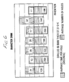
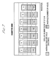
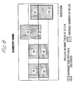
- Figures 6 to 8 are graphs comparing the life and speed of cut of 3mm, 6mm and 10mm diameter respectively roll-forged drill bits according to the present invention with known prior art roll-forged drill bits.
- With reference to the drawings, a roll-forged drill bit 1 according to the present invention comprises a shank 3 including a
solid end 5 for insertion in a chuck (not shown) of a drill, during use, and an helically twisted web 7 defining a cutting tip 9. As shown in Figure 2, the web 7 tapers from thesolid end 5 towards the cutting tip 9, so that the web 7 has a thickness at the cutting tip 9 which is less than 30% of its thickness where it joins theshank end 5. As a result, during use, "walking" of the drill bit is reduced and debris is removed from a work site in a quick and efficient manner. - With reference to Figures 3, 4 and 5 of the drawings, the cutting tip 9 comprises a chisel edge 11 defined by two
faces 13 inclined rearwardly from the chisel edge 11. Thefaces 13 define an angle therebetween of approximately 124°, which is a slighty larger angle than in most prior art roll-forged drill bits. -
Cutting edges 15 are defined byupturned flats 17, as shown in Figures 3-5 of the drawings. Thecutting edges 15 make an angle of approximately 6° with a plane perpendicular to the axis of the shank 3. As a result, the outermost part of eachcutting edge 15 produces a neat and clean cut in a workpiece, during use. - As can be seen in Figure 3 of the drawings, the
faces 13 defining the chisel edge 11 meet theflats 17 at aline 19, which defines a sudden change in the angle of the cutting tip 9. Once again, this is a substantial departure from the cutting tip arrangements known in prior art roll-forged drill bits. - By providing a roll-forged drill bit according to the present invention, a significant improvement in the performance of the drill bit 1 is produced. In this regard, as can be seen from Figures 6-8 of the drawings, drill bits 1 according to the present invention, described as "Invention" in the drawings, are shown compared against a number of other roll-forged drill bits currently in the market place. As can be seen, for drill bits having diameters of 3mm (Figure 6), 6mm (Figure 7) and 10mm (Figure 8), the drill bits according to the present invention are significantly quicker at drilling holes in workpieces without sacrificing a loss in life expectancy of the drill bit. Thus it will be appreciated that a roll-forged drill bit according to the present invention is a marked improvement over those known from the prior art.
- It will of course be understood that the present invention has been described above purely by way of example, and that modifications of detail can be made within the scope of the invention.
Claims (5)
- A roll-forged drill bit comprising a shank for insertion in a chuck of a drill, the shank including an helically twisted web defining a cutting tip, the cutting tip including a central chisel edge and a cutting edge defining the maximum diameter of the cutting tip, wherein the cutting tip is formed after the shank has been roll-forged and includes a pair of faces defining the chisel edge and a pair of upturned flats defining the cutting edge.
- A roll-forged drill bit according to claim 1, wherein the faces define an angle of between 121° and 127°.
- A roll-forged drill bit as claimed in claim 1 or claim 2, wherein the cutting edge defines an angle of between 3° and 9° with a plane perpendicular to the axis of the shank.
- A roll-forged drill bit according to any preceding claim, wherein the web tapers towards the cutting tip and has a thickness at the cutting tip which is no more than 30% of its maximum thickness.
- A roll-forged drill bit substantially as hereinbefore described with reference to and as shown in the accompanying drawings.
Applications Claiming Priority (2)
| Application Number | Priority Date | Filing Date | Title |
|---|---|---|---|
| GB9515593 | 1995-07-29 | ||
| GB9515593A GB2303809A (en) | 1995-07-29 | 1995-07-29 | Roll-forged drill bit |
Publications (2)
| Publication Number | Publication Date |
|---|---|
| EP0761352A1 true EP0761352A1 (en) | 1997-03-12 |
| EP0761352B1 EP0761352B1 (en) | 2003-10-15 |
Family
ID=10778480
Family Applications (1)
| Application Number | Title | Priority Date | Filing Date |
|---|---|---|---|
| EP96305349A Expired - Lifetime EP0761352B1 (en) | 1995-07-29 | 1996-07-22 | A roll-forged drill bit |
Country Status (4)
| Country | Link |
|---|---|
| US (1) | US6113321A (en) |
| EP (1) | EP0761352B1 (en) |
| DE (1) | DE69630344T2 (en) |
| GB (1) | GB2303809A (en) |
Cited By (6)
| Publication number | Priority date | Publication date | Assignee | Title |
|---|---|---|---|---|
| DE19807609A1 (en) * | 1997-12-15 | 1999-06-24 | Werkzeugfabrik Gmbh Koenigsee | Twist drill for drilling holes |
| WO2001091960A1 (en) * | 2000-05-26 | 2001-12-06 | Nygaard Eero | Drill bit |
| DE10106035A1 (en) * | 2001-02-09 | 2002-08-29 | Scintilla Ag | Drill bit for drilling metal has at least one cross surface formed on drill bit head |
| WO2005092547A1 (en) * | 2004-03-17 | 2005-10-06 | Kennametal Inc. | Twist drill |
| EP2018918A1 (en) * | 2007-07-26 | 2009-01-28 | Snecma | Ceramic drill for high-speed perforation of composite materials |
| US8740515B2 (en) | 2008-09-03 | 2014-06-03 | Black & Decker Inc. | Metal cutting drill bit |
Families Citing this family (23)
| Publication number | Priority date | Publication date | Assignee | Title |
|---|---|---|---|---|
| US6419561B1 (en) | 2000-10-05 | 2002-07-16 | Kennametal Inc. | Method and apparatus for making a cutting tool having a plurality of margins |
| US6602029B1 (en) | 2000-10-05 | 2003-08-05 | Kennametal Inc. | Cutting tool and method and apparatus for making the same |
| US6431962B1 (en) | 2000-10-05 | 2002-08-13 | Kennametal Inc. | Method and apparatus for making a cutting tool having a flute |
| DE20210909U1 (en) * | 2002-07-18 | 2003-05-15 | Hakos Praez Swerkzeuge Hakenjo | drilling |
| JP3720010B2 (en) * | 2002-10-02 | 2005-11-24 | オーエスジー株式会社 | Deep hole drill |
| FR2850435B1 (en) * | 2003-01-29 | 2007-07-13 | Prospection & Inventions | ANCHORING ANKLE FOR FRIENDLY MATERIAL |
| JP2004268165A (en) * | 2003-03-05 | 2004-09-30 | Honda Motor Co Ltd | Deep hole machining drill |
| US20050053439A1 (en) | 2003-09-09 | 2005-03-10 | Yuhong Wang | Two-flute twist drill |
| US7237986B2 (en) * | 2004-08-09 | 2007-07-03 | Black & Decker Inc. | High speed metal drill bit |
| GB2428611B (en) * | 2005-08-02 | 2007-10-03 | Dormer Tools | Twist drill |
| CN2820394Y (en) * | 2005-09-14 | 2006-09-27 | 江苏天工工具股份有限公司 | Filing separating strong drill |
| DE102007042279A1 (en) * | 2007-09-06 | 2009-03-12 | Komet Group Holding Gmbh | Drilling tool for machine tools and method for its production |
| SE532432C2 (en) * | 2008-05-09 | 2010-01-19 | Sandvik Intellectual Property | Drill body with primary and secondary release surfaces |
| CA2712796A1 (en) * | 2009-08-06 | 2011-02-06 | Textron Innovations Inc. | Hole saw with tapered pilot bit |
| US9539652B2 (en) | 2010-04-30 | 2017-01-10 | Kennametal Inc. | Rotary cutting tool having PCD cutting tip |
| EP2502709B1 (en) | 2011-03-22 | 2017-02-01 | Black & Decker Inc. | Chisels |
| WO2014015154A1 (en) | 2012-07-18 | 2014-01-23 | Milwaukee Electric Tool Corporation | Hole saw |
| USD737875S1 (en) | 2013-03-15 | 2015-09-01 | Black & Decker Inc. | Drill bit |
| USD734792S1 (en) | 2013-03-15 | 2015-07-21 | Black & Decker Inc. | Drill bit |
| US9333564B2 (en) | 2013-03-15 | 2016-05-10 | Black & Decker Inc. | Drill bit |
| CN105397438A (en) * | 2015-12-31 | 2016-03-16 | 武汉江钻恒立工程钻具股份有限公司 | Manufacture method of way-type drilling unit |
| CN216028284U (en) | 2018-07-10 | 2022-03-15 | 米沃奇电动工具公司 | Hole saw |
| USD958855S1 (en) | 2019-12-09 | 2022-07-26 | Milwaukee Electric Tool Corporation | Hole saw |
Citations (5)
| Publication number | Priority date | Publication date | Assignee | Title |
|---|---|---|---|---|
| DE1918587A1 (en) * | 1969-04-11 | 1970-10-22 | ||
| US3893353A (en) * | 1970-12-28 | 1975-07-08 | Heller Geb | Drill and method of producing the same |
| EP0137898A1 (en) * | 1983-10-04 | 1985-04-24 | Rolf Klenk Hartmetallwerkzeugfabrik GmbH & Co. KG | Solid hard metal twist drill for machining materials difficult to machine |
| US4556347A (en) * | 1984-05-11 | 1985-12-03 | Lockheed Corporation | Split-point twist drill |
| US4878788A (en) * | 1988-08-04 | 1989-11-07 | Kabushiki Kaisha Kobe Seiko Sho | Drill for drilling a thin plate |
Family Cites Families (34)
| Publication number | Priority date | Publication date | Assignee | Title |
|---|---|---|---|---|
| US1017352A (en) * | 1911-12-21 | 1912-02-13 | Frederick A Wagner | Combined drill, center-reamer, and countersink tool. |
| GB519475A (en) * | 1938-10-18 | 1940-03-28 | Thomas Alexander Forsyth | Improvements in and relating to drilling tools |
| US2332295A (en) * | 1941-11-07 | 1943-10-19 | Western Electric Co | Drill |
| US2600286A (en) * | 1947-09-08 | 1952-06-10 | Bell Machine Company | Drill bit |
| US2673714A (en) * | 1950-08-05 | 1954-03-30 | John M Hargrave | Rock or masonry drill |
| FR1111617A (en) * | 1954-09-17 | 1956-03-02 | Further training in drills | |
| US3076357A (en) * | 1961-08-21 | 1963-02-05 | Erickson Tool Co | Spade drill blade |
| US3199381A (en) * | 1963-03-04 | 1965-08-10 | Bruce A Mackey | Twist drill |
| US3592555A (en) * | 1969-05-02 | 1971-07-13 | Radial Lip Machine Corp | Drill with discontinuous cutting lips |
| GB1378342A (en) * | 1972-09-28 | 1974-12-27 | Perkins & Smith Ltd | Tip for drill bit |
| DE2422452A1 (en) * | 1974-05-09 | 1975-11-20 | Madison Ind Gmbh | Boring cutter with lateral guide - has diagonal lateral guide ribs to ensure high lateral stability |
| DE3123048C2 (en) * | 1981-02-12 | 1983-06-16 | Paul 5630 Remscheid Schmitz | Twist drill |
| US4503920A (en) * | 1981-08-10 | 1985-03-12 | Burke Clement | Masonry bit |
| EP0088037A1 (en) * | 1982-02-24 | 1983-09-07 | Hughes Tool Company | Single pass drill |
| US4529341A (en) * | 1982-09-29 | 1985-07-16 | Hughes Helicopters, Inc. | Drill bit for Kevlar laminates |
| DE8303526U1 (en) * | 1983-02-09 | 1983-06-30 | Schmitz, Paul, 5630 Remscheid | SPIRAL DRILL |
| DE3316193A1 (en) * | 1983-05-04 | 1984-11-08 | Haberer und Hirt Hydraulik-Service und Werkzeuge GmbH, 7623 Schenkenzell | Removal of a first metal sheet secured to a second metal sheet by spot welding |
| DE3426977A1 (en) * | 1984-07-21 | 1986-01-30 | Hawera Probst Gmbh + Co, 7980 Ravensburg | ROCK DRILL |
| SU1238905A1 (en) * | 1984-09-12 | 1986-06-23 | Харьковский Ордена Ленина Политехнический Институт Им.В.И.Ленина | Drill for working composition polymer materials |
| FR2583667A1 (en) * | 1985-06-19 | 1986-12-26 | Girouard Marc | Drill bit for materials which are difficult to machine |
| DE3538191C2 (en) * | 1985-10-26 | 1996-09-19 | Hilti Ag | Rock drill |
| US4968193A (en) * | 1986-08-18 | 1990-11-06 | Black & Decker Corporation | Self-centering drill bit with pilot tip |
| US4984944A (en) * | 1987-02-09 | 1991-01-15 | Vermont American Corporation | Drill bit blade for masonry and rock drill |
| GB2201910A (en) * | 1987-02-23 | 1988-09-14 | Joseph Spencer | Drilling bit |
| US5011342A (en) * | 1988-03-14 | 1991-04-30 | 501 Greenfield Industries, Inc. | Twist drill |
| DE3813849A1 (en) * | 1988-04-23 | 1989-11-02 | Hawera Probst Kg Hartmetall | ROCK DRILL |
| JPH0215908A (en) * | 1988-07-04 | 1990-01-19 | Toshiaki Hosoi | Drill and its grinding method and device |
| JPH0237709A (en) * | 1988-07-27 | 1990-02-07 | Nikon Corp | Aligner |
| US5056967A (en) * | 1989-03-28 | 1991-10-15 | Premier Industrial Corporation | Spotweld removal tool |
| JPH03117507A (en) * | 1989-09-29 | 1991-05-20 | Kobe Steel Ltd | Drill |
| JPH04244311A (en) * | 1991-01-29 | 1992-09-01 | Hitachi Ltd | Three-stage-web, tapered drill |
| DE4117486C2 (en) * | 1991-05-28 | 1995-07-27 | Hitachi Seiko Kk | drill |
| SE507842C2 (en) * | 1992-09-24 | 1998-07-20 | Sandvik Ab | Drill |
| US5570978A (en) * | 1994-12-05 | 1996-11-05 | Rees; John X. | High performance cutting tools |
-
1995
- 1995-07-29 GB GB9515593A patent/GB2303809A/en not_active Withdrawn
-
1996
- 1996-07-22 DE DE69630344T patent/DE69630344T2/en not_active Expired - Lifetime
- 1996-07-22 EP EP96305349A patent/EP0761352B1/en not_active Expired - Lifetime
- 1996-07-25 US US08/686,284 patent/US6113321A/en not_active Expired - Lifetime
Patent Citations (5)
| Publication number | Priority date | Publication date | Assignee | Title |
|---|---|---|---|---|
| DE1918587A1 (en) * | 1969-04-11 | 1970-10-22 | ||
| US3893353A (en) * | 1970-12-28 | 1975-07-08 | Heller Geb | Drill and method of producing the same |
| EP0137898A1 (en) * | 1983-10-04 | 1985-04-24 | Rolf Klenk Hartmetallwerkzeugfabrik GmbH & Co. KG | Solid hard metal twist drill for machining materials difficult to machine |
| US4556347A (en) * | 1984-05-11 | 1985-12-03 | Lockheed Corporation | Split-point twist drill |
| US4878788A (en) * | 1988-08-04 | 1989-11-07 | Kabushiki Kaisha Kobe Seiko Sho | Drill for drilling a thin plate |
Cited By (12)
| Publication number | Priority date | Publication date | Assignee | Title |
|---|---|---|---|---|
| DE19807609A1 (en) * | 1997-12-15 | 1999-06-24 | Werkzeugfabrik Gmbh Koenigsee | Twist drill for drilling holes |
| DE19807609B4 (en) * | 1997-12-15 | 2004-03-25 | Werkzeugfabrik Königsee Zweigniederlassung der Widia GmbH | twist drill |
| WO2001091960A1 (en) * | 2000-05-26 | 2001-12-06 | Nygaard Eero | Drill bit |
| DE10106035A1 (en) * | 2001-02-09 | 2002-08-29 | Scintilla Ag | Drill bit for drilling metal has at least one cross surface formed on drill bit head |
| DE10106035B4 (en) * | 2001-02-09 | 2008-12-11 | Scintilla Ag | metal drill |
| WO2005092547A1 (en) * | 2004-03-17 | 2005-10-06 | Kennametal Inc. | Twist drill |
| CN100417479C (en) * | 2004-03-17 | 2008-09-10 | 钴碳化钨硬质合金公司 | Twist drill |
| US7837418B2 (en) | 2004-03-17 | 2010-11-23 | Kennametal Inc. | Twist drill |
| EP2018918A1 (en) * | 2007-07-26 | 2009-01-28 | Snecma | Ceramic drill for high-speed perforation of composite materials |
| FR2919212A1 (en) * | 2007-07-26 | 2009-01-30 | Snecma Sa | CERAMIC DRILL FOR HIGH SPEED DRILLING OF COMPOSITE MATERIALS. |
| US8206067B2 (en) | 2007-07-26 | 2012-06-26 | Snecma | Ceramic drill bit for high-speed drilling of composites |
| US8740515B2 (en) | 2008-09-03 | 2014-06-03 | Black & Decker Inc. | Metal cutting drill bit |
Also Published As
| Publication number | Publication date |
|---|---|
| US6113321A (en) | 2000-09-05 |
| EP0761352B1 (en) | 2003-10-15 |
| DE69630344D1 (en) | 2003-11-20 |
| GB9515593D0 (en) | 1995-09-27 |
| DE69630344T2 (en) | 2004-05-13 |
| GB2303809A (en) | 1997-03-05 |
Similar Documents
| Publication | Publication Date | Title |
|---|---|---|
| US6113321A (en) | Roll-forged drill bit | |
| US6102634A (en) | Masonry drill bit | |
| KR100838767B1 (en) | Twist drill | |
| US4507028A (en) | Combined drill and reamer | |
| US5273380A (en) | Drill bit point | |
| US6857832B2 (en) | Drill bit with pilot point | |
| US5387059A (en) | Drill bit with improved stability | |
| WO2003035310A1 (en) | Tool for chip forming machining | |
| US4449865A (en) | Method and tool for generating countersunk holes in composite materials | |
| JP2002144124A (en) | Small drill | |
| EP1037724B1 (en) | Multi-bit drill | |
| JP3988659B2 (en) | Drill | |
| JP3985713B2 (en) | Drill | |
| KR920008792B1 (en) | Twist drill | |
| GB2449789A (en) | Improved Spade Type Bit | |
| JPH11156811A (en) | Auger for woodworking | |
| JPH10151604A (en) | Woodworking boring drill | |
| JP2002079408A (en) | Stepped drill | |
| JPH10315021A (en) | Drill | |
| JP2002028810A (en) | Small-sized drill | |
| JPS63318207A (en) | Drill | |
| JPH1158117A (en) | Drill | |
| JP2006224213A (en) | Twist drill | |
| JPS5929366B2 (en) | drilling tool | |
| JP2001087919A (en) | Drill structure |
Legal Events
| Date | Code | Title | Description |
|---|---|---|---|
| PUAI | Public reference made under article 153(3) epc to a published international application that has entered the european phase |
Free format text: ORIGINAL CODE: 0009012 |
|
| AK | Designated contracting states |
Kind code of ref document: A1 Designated state(s): BE DE FR GB NL SE |
|
| 17P | Request for examination filed |
Effective date: 19970910 |
|
| 17Q | First examination report despatched |
Effective date: 19980513 |
|
| APAB | Appeal dossier modified |
Free format text: ORIGINAL CODE: EPIDOS NOAPE |
|
| APAB | Appeal dossier modified |
Free format text: ORIGINAL CODE: EPIDOS NOAPE |
|
| APBJ | Interlocutory revision of appeal recorded |
Free format text: ORIGINAL CODE: EPIDOS IRAPE |
|
| GRAH | Despatch of communication of intention to grant a patent |
Free format text: ORIGINAL CODE: EPIDOS IGRA |
|
| GRAH | Despatch of communication of intention to grant a patent |
Free format text: ORIGINAL CODE: EPIDOS IGRA |
|
| GRAA | (expected) grant |
Free format text: ORIGINAL CODE: 0009210 |
|
| AK | Designated contracting states |
Kind code of ref document: B1 Designated state(s): BE DE FR GB NL SE |
|
| PG25 | Lapsed in a contracting state [announced via postgrant information from national office to epo] |
Ref country code: BE Free format text: LAPSE BECAUSE OF FAILURE TO SUBMIT A TRANSLATION OF THE DESCRIPTION OR TO PAY THE FEE WITHIN THE PRESCRIBED TIME-LIMIT Effective date: 20031015 |
|
| REG | Reference to a national code |
Ref country code: GB Ref legal event code: FG4D |
|
| REF | Corresponds to: |
Ref document number: 69630344 Country of ref document: DE Date of ref document: 20031120 Kind code of ref document: P |
|
| REG | Reference to a national code |
Ref country code: SE Ref legal event code: TRGR |
|
| ET | Fr: translation filed | ||
| PLBE | No opposition filed within time limit |
Free format text: ORIGINAL CODE: 0009261 |
|
| STAA | Information on the status of an ep patent application or granted ep patent |
Free format text: STATUS: NO OPPOSITION FILED WITHIN TIME LIMIT |
|
| 26N | No opposition filed |
Effective date: 20040716 |
|
| PGFP | Annual fee paid to national office [announced via postgrant information from national office to epo] |
Ref country code: SE Payment date: 20070727 Year of fee payment: 12 Ref country code: NL Payment date: 20070724 Year of fee payment: 12 |
|
| EUG | Se: european patent has lapsed | ||
| NLV4 | Nl: lapsed or anulled due to non-payment of the annual fee |
Effective date: 20090201 |
|
| PG25 | Lapsed in a contracting state [announced via postgrant information from national office to epo] |
Ref country code: NL Free format text: LAPSE BECAUSE OF NON-PAYMENT OF DUE FEES Effective date: 20090201 |
|
| PGFP | Annual fee paid to national office [announced via postgrant information from national office to epo] |
Ref country code: FR Payment date: 20090717 Year of fee payment: 14 |
|
| PG25 | Lapsed in a contracting state [announced via postgrant information from national office to epo] |
Ref country code: SE Free format text: LAPSE BECAUSE OF NON-PAYMENT OF DUE FEES Effective date: 20080723 |
|
| REG | Reference to a national code |
Ref country code: FR Ref legal event code: ST Effective date: 20110331 |
|
| PG25 | Lapsed in a contracting state [announced via postgrant information from national office to epo] |
Ref country code: FR Free format text: LAPSE BECAUSE OF NON-PAYMENT OF DUE FEES Effective date: 20100802 |
|
| PGFP | Annual fee paid to national office [announced via postgrant information from national office to epo] |
Ref country code: GB Payment date: 20120725 Year of fee payment: 17 |
|
| PGFP | Annual fee paid to national office [announced via postgrant information from national office to epo] |
Ref country code: DE Payment date: 20120727 Year of fee payment: 17 |
|
| GBPC | Gb: european patent ceased through non-payment of renewal fee |
Effective date: 20130722 |
|
| REG | Reference to a national code |
Ref country code: DE Ref legal event code: R119 Ref document number: 69630344 Country of ref document: DE Effective date: 20140201 |
|
| PG25 | Lapsed in a contracting state [announced via postgrant information from national office to epo] |
Ref country code: GB Free format text: LAPSE BECAUSE OF NON-PAYMENT OF DUE FEES Effective date: 20130722 Ref country code: DE Free format text: LAPSE BECAUSE OF NON-PAYMENT OF DUE FEES Effective date: 20140201 |