EP0760919B1 - Sanitizable slider diaphragm valve - Google Patents
Sanitizable slider diaphragm valve Download PDFInfo
- Publication number
- EP0760919B1 EP0760919B1 EP95921324A EP95921324A EP0760919B1 EP 0760919 B1 EP0760919 B1 EP 0760919B1 EP 95921324 A EP95921324 A EP 95921324A EP 95921324 A EP95921324 A EP 95921324A EP 0760919 B1 EP0760919 B1 EP 0760919B1
- Authority
- EP
- European Patent Office
- Prior art keywords
- stator
- rotor
- diaphragm
- port
- ports
- Prior art date
- Legal status (The legal status is an assumption and is not a legal conclusion. Google has not performed a legal analysis and makes no representation as to the accuracy of the status listed.)
- Expired - Lifetime
Links
- 238000007789 sealing Methods 0.000 claims abstract description 116
- 239000012530 fluid Substances 0.000 claims abstract description 103
- 238000011012 sanitization Methods 0.000 claims abstract description 21
- 238000011010 flushing procedure Methods 0.000 claims abstract description 9
- 238000013375 chromatographic separation Methods 0.000 claims abstract description 4
- 230000004888 barrier function Effects 0.000 claims description 60
- 238000000034 method Methods 0.000 claims description 25
- 230000008569 process Effects 0.000 claims description 24
- 238000000926 separation method Methods 0.000 claims description 18
- 238000004891 communication Methods 0.000 claims description 15
- 239000007788 liquid Substances 0.000 claims description 14
- 229920001971 elastomer Polymers 0.000 claims description 5
- 238000000465 moulding Methods 0.000 claims description 4
- 239000000806 elastomer Substances 0.000 claims description 3
- 238000003860 storage Methods 0.000 claims description 3
- 238000001746 injection moulding Methods 0.000 claims description 2
- 238000005452 bending Methods 0.000 claims 1
- 230000002040 relaxant effect Effects 0.000 claims 1
- 239000007790 solid phase Substances 0.000 abstract description 9
- 229920001169 thermoplastic Polymers 0.000 abstract description 4
- 239000004416 thermosoftening plastic Substances 0.000 abstract description 3
- 238000004587 chromatography analysis Methods 0.000 abstract description 2
- 229960000074 biopharmaceutical Drugs 0.000 abstract 1
- 239000000463 material Substances 0.000 description 13
- 239000003480 eluent Substances 0.000 description 12
- 239000000047 product Substances 0.000 description 11
- 238000001179 sorption measurement Methods 0.000 description 11
- 229920005989 resin Polymers 0.000 description 10
- 239000011347 resin Substances 0.000 description 10
- HEMHJVSKTPXQMS-UHFFFAOYSA-M Sodium hydroxide Chemical compound [OH-].[Na+] HEMHJVSKTPXQMS-UHFFFAOYSA-M 0.000 description 9
- 238000004140 cleaning Methods 0.000 description 7
- 230000013011 mating Effects 0.000 description 6
- -1 polythalamide (PPA) Polymers 0.000 description 6
- 238000013461 design Methods 0.000 description 5
- 238000005194 fractionation Methods 0.000 description 5
- 238000005342 ion exchange Methods 0.000 description 5
- 239000000243 solution Substances 0.000 description 5
- 239000003463 adsorbent Substances 0.000 description 4
- 238000011021 bench scale process Methods 0.000 description 4
- 239000000356 contaminant Substances 0.000 description 4
- 238000010586 diagram Methods 0.000 description 4
- 239000007791 liquid phase Substances 0.000 description 4
- 238000011020 pilot scale process Methods 0.000 description 4
- 230000008929 regeneration Effects 0.000 description 4
- 238000011069 regeneration method Methods 0.000 description 4
- 239000004696 Poly ether ether ketone Substances 0.000 description 3
- 239000004734 Polyphenylene sulfide Substances 0.000 description 3
- 238000009825 accumulation Methods 0.000 description 3
- 239000002156 adsorbate Substances 0.000 description 3
- 238000009826 distribution Methods 0.000 description 3
- 239000003814 drug Substances 0.000 description 3
- 230000003993 interaction Effects 0.000 description 3
- 238000004811 liquid chromatography Methods 0.000 description 3
- 229920002530 polyetherether ketone Polymers 0.000 description 3
- 229920000069 polyphenylene sulfide Polymers 0.000 description 3
- 230000000717 retained effect Effects 0.000 description 3
- 150000003839 salts Chemical class 0.000 description 3
- 239000002904 solvent Substances 0.000 description 3
- 238000012546 transfer Methods 0.000 description 3
- AFABGHUZZDYHJO-UHFFFAOYSA-N 2-Methylpentane Chemical compound CCCC(C)C AFABGHUZZDYHJO-UHFFFAOYSA-N 0.000 description 2
- 239000004698 Polyethylene Substances 0.000 description 2
- 229920000491 Polyphenylsulfone Polymers 0.000 description 2
- 239000004743 Polypropylene Substances 0.000 description 2
- CDBYLPFSWZWCQE-UHFFFAOYSA-L Sodium Carbonate Chemical compound [Na+].[Na+].[O-]C([O-])=O CDBYLPFSWZWCQE-UHFFFAOYSA-L 0.000 description 2
- 238000005299 abrasion Methods 0.000 description 2
- 230000009471 action Effects 0.000 description 2
- 239000003795 chemical substances by application Substances 0.000 description 2
- 238000010276 construction Methods 0.000 description 2
- 238000011109 contamination Methods 0.000 description 2
- 238000003795 desorption Methods 0.000 description 2
- 238000006073 displacement reaction Methods 0.000 description 2
- 230000003028 elevating effect Effects 0.000 description 2
- 238000010828 elution Methods 0.000 description 2
- 230000007717 exclusion Effects 0.000 description 2
- 235000013305 food Nutrition 0.000 description 2
- 238000011068 loading method Methods 0.000 description 2
- 238000004519 manufacturing process Methods 0.000 description 2
- 230000036961 partial effect Effects 0.000 description 2
- 239000012071 phase Substances 0.000 description 2
- 229920000573 polyethylene Polymers 0.000 description 2
- 229920001155 polypropylene Polymers 0.000 description 2
- 238000010992 reflux Methods 0.000 description 2
- 230000000630 rising effect Effects 0.000 description 2
- 239000005060 rubber Substances 0.000 description 2
- 239000007787 solid Substances 0.000 description 2
- 239000002594 sorbent Substances 0.000 description 2
- 229920002725 thermoplastic elastomer Polymers 0.000 description 2
- 239000002699 waste material Substances 0.000 description 2
- YUHZIUAREWNXJT-UHFFFAOYSA-N (2-fluoropyridin-3-yl)boronic acid Chemical class OB(O)C1=CC=CN=C1F YUHZIUAREWNXJT-UHFFFAOYSA-N 0.000 description 1
- 229930091371 Fructose Natural products 0.000 description 1
- 239000005715 Fructose Substances 0.000 description 1
- RFSUNEUAIZKAJO-ARQDHWQXSA-N Fructose Chemical compound OC[C@H]1O[C@](O)(CO)[C@@H](O)[C@@H]1O RFSUNEUAIZKAJO-ARQDHWQXSA-N 0.000 description 1
- WQZGKKKJIJFFOK-GASJEMHNSA-N Glucose Natural products OC[C@H]1OC(O)[C@H](O)[C@@H](O)[C@@H]1O WQZGKKKJIJFFOK-GASJEMHNSA-N 0.000 description 1
- 229920002633 Kraton (polymer) Polymers 0.000 description 1
- 229920006362 Teflon® Polymers 0.000 description 1
- 229920006355 Tefzel Polymers 0.000 description 1
- 240000008042 Zea mays Species 0.000 description 1
- 235000005824 Zea mays ssp. parviglumis Nutrition 0.000 description 1
- 235000002017 Zea mays subsp mays Nutrition 0.000 description 1
- 230000007059 acute toxicity Effects 0.000 description 1
- 231100000403 acute toxicity Toxicity 0.000 description 1
- 239000000443 aerosol Substances 0.000 description 1
- 239000000956 alloy Substances 0.000 description 1
- 229910045601 alloy Inorganic materials 0.000 description 1
- 229910052782 aluminium Inorganic materials 0.000 description 1
- XAGFODPZIPBFFR-UHFFFAOYSA-N aluminium Chemical compound [Al] XAGFODPZIPBFFR-UHFFFAOYSA-N 0.000 description 1
- 238000003491 array Methods 0.000 description 1
- 230000000712 assembly Effects 0.000 description 1
- 238000000429 assembly Methods 0.000 description 1
- WQZGKKKJIJFFOK-VFUOTHLCSA-N beta-D-glucose Chemical compound OC[C@H]1O[C@@H](O)[C@H](O)[C@@H](O)[C@@H]1O WQZGKKKJIJFFOK-VFUOTHLCSA-N 0.000 description 1
- 235000013361 beverage Nutrition 0.000 description 1
- 239000000872 buffer Substances 0.000 description 1
- 239000006227 byproduct Substances 0.000 description 1
- 229910010293 ceramic material Inorganic materials 0.000 description 1
- 239000013522 chelant Substances 0.000 description 1
- 238000004440 column chromatography Methods 0.000 description 1
- 230000006835 compression Effects 0.000 description 1
- 238000007906 compression Methods 0.000 description 1
- 239000012141 concentrate Substances 0.000 description 1
- 235000005822 corn Nutrition 0.000 description 1
- 238000005260 corrosion Methods 0.000 description 1
- 230000007797 corrosion Effects 0.000 description 1
- 230000008878 coupling Effects 0.000 description 1
- 238000010168 coupling process Methods 0.000 description 1
- 238000005859 coupling reaction Methods 0.000 description 1
- 238000012864 cross contamination Methods 0.000 description 1
- 230000001186 cumulative effect Effects 0.000 description 1
- 230000000694 effects Effects 0.000 description 1
- 229920006351 engineering plastic Polymers 0.000 description 1
- 229920003247 engineering thermoplastic Polymers 0.000 description 1
- 230000007613 environmental effect Effects 0.000 description 1
- QHSJIZLJUFMIFP-UHFFFAOYSA-N ethene;1,1,2,2-tetrafluoroethene Chemical compound C=C.FC(F)=C(F)F QHSJIZLJUFMIFP-UHFFFAOYSA-N 0.000 description 1
- 239000012632 extractable Substances 0.000 description 1
- 239000012527 feed solution Substances 0.000 description 1
- 239000008103 glucose Substances 0.000 description 1
- 150000004676 glycans Chemical class 0.000 description 1
- VLKZOEOYAKHREP-UHFFFAOYSA-N hexane Substances CCCCCC VLKZOEOYAKHREP-UHFFFAOYSA-N 0.000 description 1
- 239000012761 high-performance material Substances 0.000 description 1
- 229930195733 hydrocarbon Natural products 0.000 description 1
- 150000002430 hydrocarbons Chemical class 0.000 description 1
- 230000002209 hydrophobic effect Effects 0.000 description 1
- 238000002347 injection Methods 0.000 description 1
- 239000007924 injection Substances 0.000 description 1
- 238000002955 isolation Methods 0.000 description 1
- 238000005304 joining Methods 0.000 description 1
- 238000002386 leaching Methods 0.000 description 1
- 230000000670 limiting effect Effects 0.000 description 1
- 230000001050 lubricating effect Effects 0.000 description 1
- 238000003754 machining Methods 0.000 description 1
- 229920002521 macromolecule Polymers 0.000 description 1
- 229910052751 metal Inorganic materials 0.000 description 1
- 239000002184 metal Substances 0.000 description 1
- 244000005700 microbiome Species 0.000 description 1
- 230000005012 migration Effects 0.000 description 1
- 238000013508 migration Methods 0.000 description 1
- 238000002156 mixing Methods 0.000 description 1
- 239000000203 mixture Substances 0.000 description 1
- 238000012856 packing Methods 0.000 description 1
- 230000000737 periodic effect Effects 0.000 description 1
- 230000002093 peripheral effect Effects 0.000 description 1
- 239000004033 plastic Substances 0.000 description 1
- 229920003023 plastic Polymers 0.000 description 1
- 238000009428 plumbing Methods 0.000 description 1
- 229920002493 poly(chlorotrifluoroethylene) Polymers 0.000 description 1
- 229920002492 poly(sulfone) Polymers 0.000 description 1
- 239000005023 polychlorotrifluoroethylene (PCTFE) polymer Substances 0.000 description 1
- 229920001282 polysaccharide Polymers 0.000 description 1
- 239000005017 polysaccharide Substances 0.000 description 1
- 229920005996 polystyrene-poly(ethylene-butylene)-polystyrene Polymers 0.000 description 1
- 102000004196 processed proteins & peptides Human genes 0.000 description 1
- 108090000765 processed proteins & peptides Proteins 0.000 description 1
- 238000012545 processing Methods 0.000 description 1
- 102000004169 proteins and genes Human genes 0.000 description 1
- 108090000623 proteins and genes Proteins 0.000 description 1
- 238000010926 purge Methods 0.000 description 1
- 238000000746 purification Methods 0.000 description 1
- 230000002829 reductive effect Effects 0.000 description 1
- 239000012492 regenerant Substances 0.000 description 1
- 230000001105 regulatory effect Effects 0.000 description 1
- 230000002441 reversible effect Effects 0.000 description 1
- 229920006395 saturated elastomer Polymers 0.000 description 1
- 230000035939 shock Effects 0.000 description 1
- 235000017550 sodium carbonate Nutrition 0.000 description 1
- 229910000029 sodium carbonate Inorganic materials 0.000 description 1
- 238000002336 sorption--desorption measurement Methods 0.000 description 1
- 241000894007 species Species 0.000 description 1
- 239000010935 stainless steel Substances 0.000 description 1
- 229910001220 stainless steel Inorganic materials 0.000 description 1
- 230000003068 static effect Effects 0.000 description 1
- 239000008227 sterile water for injection Substances 0.000 description 1
- 239000012536 storage buffer Substances 0.000 description 1
- 239000006188 syrup Substances 0.000 description 1
- 235000020357 syrup Nutrition 0.000 description 1
- 238000012360 testing method Methods 0.000 description 1
- 230000001988 toxicity Effects 0.000 description 1
- 231100000419 toxicity Toxicity 0.000 description 1
- 238000011144 upstream manufacturing Methods 0.000 description 1
- 239000011800 void material Substances 0.000 description 1
- 239000011534 wash buffer Substances 0.000 description 1
- 238000005406 washing Methods 0.000 description 1
- XLYOFNOQVPJJNP-UHFFFAOYSA-N water Chemical compound O XLYOFNOQVPJJNP-UHFFFAOYSA-N 0.000 description 1
Images


Classifications
-
- B—PERFORMING OPERATIONS; TRANSPORTING
- B01—PHYSICAL OR CHEMICAL PROCESSES OR APPARATUS IN GENERAL
- B01D—SEPARATION
- B01D53/00—Separation of gases or vapours; Recovering vapours of volatile solvents from gases; Chemical or biological purification of waste gases, e.g. engine exhaust gases, smoke, fumes, flue gases, aerosols
- B01D53/02—Separation of gases or vapours; Recovering vapours of volatile solvents from gases; Chemical or biological purification of waste gases, e.g. engine exhaust gases, smoke, fumes, flue gases, aerosols by adsorption, e.g. preparative gas chromatography
- B01D53/04—Separation of gases or vapours; Recovering vapours of volatile solvents from gases; Chemical or biological purification of waste gases, e.g. engine exhaust gases, smoke, fumes, flue gases, aerosols by adsorption, e.g. preparative gas chromatography with stationary adsorbents
- B01D53/0407—Constructional details of adsorbing systems
- B01D53/0446—Means for feeding or distributing gases
-
- F—MECHANICAL ENGINEERING; LIGHTING; HEATING; WEAPONS; BLASTING
- F16—ENGINEERING ELEMENTS AND UNITS; GENERAL MEASURES FOR PRODUCING AND MAINTAINING EFFECTIVE FUNCTIONING OF MACHINES OR INSTALLATIONS; THERMAL INSULATION IN GENERAL
- F16K—VALVES; TAPS; COCKS; ACTUATING-FLOATS; DEVICES FOR VENTING OR AERATING
- F16K11/00—Multiple-way valves, e.g. mixing valves; Pipe fittings incorporating such valves
- F16K11/02—Multiple-way valves, e.g. mixing valves; Pipe fittings incorporating such valves with all movable sealing faces moving as one unit
- F16K11/06—Multiple-way valves, e.g. mixing valves; Pipe fittings incorporating such valves with all movable sealing faces moving as one unit comprising only sliding valves, i.e. sliding closure elements
- F16K11/072—Multiple-way valves, e.g. mixing valves; Pipe fittings incorporating such valves with all movable sealing faces moving as one unit comprising only sliding valves, i.e. sliding closure elements with pivoted closure members
- F16K11/074—Multiple-way valves, e.g. mixing valves; Pipe fittings incorporating such valves with all movable sealing faces moving as one unit comprising only sliding valves, i.e. sliding closure elements with pivoted closure members with flat sealing faces
-
- F—MECHANICAL ENGINEERING; LIGHTING; HEATING; WEAPONS; BLASTING
- F16—ENGINEERING ELEMENTS AND UNITS; GENERAL MEASURES FOR PRODUCING AND MAINTAINING EFFECTIVE FUNCTIONING OF MACHINES OR INSTALLATIONS; THERMAL INSULATION IN GENERAL
- F16K—VALVES; TAPS; COCKS; ACTUATING-FLOATS; DEVICES FOR VENTING OR AERATING
- F16K25/00—Details relating to contact between valve members and seats
- F16K25/02—Arrangements using fluid issuing from valve members or seats
-
- B—PERFORMING OPERATIONS; TRANSPORTING
- B01—PHYSICAL OR CHEMICAL PROCESSES OR APPARATUS IN GENERAL
- B01D—SEPARATION
- B01D2253/00—Adsorbents used in seperation treatment of gases and vapours
- B01D2253/20—Organic adsorbents
- B01D2253/206—Ion exchange resins
-
- B—PERFORMING OPERATIONS; TRANSPORTING
- B01—PHYSICAL OR CHEMICAL PROCESSES OR APPARATUS IN GENERAL
- B01D—SEPARATION
- B01D2259/00—Type of treatment
- B01D2259/40—Further details for adsorption processes and devices
- B01D2259/40003—Methods relating to valve switching
- B01D2259/40005—Methods relating to valve switching using rotary valves
-
- B—PERFORMING OPERATIONS; TRANSPORTING
- B01—PHYSICAL OR CHEMICAL PROCESSES OR APPARATUS IN GENERAL
- B01D—SEPARATION
- B01D2259/00—Type of treatment
- B01D2259/40—Further details for adsorption processes and devices
- B01D2259/40011—Methods relating to the process cycle in pressure or temperature swing adsorption
- B01D2259/40077—Direction of flow
- B01D2259/40081—Counter-current
-
- B—PERFORMING OPERATIONS; TRANSPORTING
- B01—PHYSICAL OR CHEMICAL PROCESSES OR APPARATUS IN GENERAL
- B01D—SEPARATION
- B01D2259/00—Type of treatment
- B01D2259/40—Further details for adsorption processes and devices
- B01D2259/406—Further details for adsorption processes and devices using more than four beds
- B01D2259/4061—Further details for adsorption processes and devices using more than four beds using five beds
-
- B—PERFORMING OPERATIONS; TRANSPORTING
- B01—PHYSICAL OR CHEMICAL PROCESSES OR APPARATUS IN GENERAL
- B01D—SEPARATION
- B01D2259/00—Type of treatment
- B01D2259/40—Further details for adsorption processes and devices
- B01D2259/406—Further details for adsorption processes and devices using more than four beds
- B01D2259/4065—Further details for adsorption processes and devices using more than four beds using eight beds
-
- B—PERFORMING OPERATIONS; TRANSPORTING
- B01—PHYSICAL OR CHEMICAL PROCESSES OR APPARATUS IN GENERAL
- B01D—SEPARATION
- B01D2259/00—Type of treatment
- B01D2259/40—Further details for adsorption processes and devices
- B01D2259/406—Further details for adsorption processes and devices using more than four beds
- B01D2259/4068—Further details for adsorption processes and devices using more than four beds using more than ten beds
-
- Y—GENERAL TAGGING OF NEW TECHNOLOGICAL DEVELOPMENTS; GENERAL TAGGING OF CROSS-SECTIONAL TECHNOLOGIES SPANNING OVER SEVERAL SECTIONS OF THE IPC; TECHNICAL SUBJECTS COVERED BY FORMER USPC CROSS-REFERENCE ART COLLECTIONS [XRACs] AND DIGESTS
- Y10—TECHNICAL SUBJECTS COVERED BY FORMER USPC
- Y10T—TECHNICAL SUBJECTS COVERED BY FORMER US CLASSIFICATION
- Y10T137/00—Fluid handling
- Y10T137/4238—With cleaner, lubrication added to fluid or liquid sealing at valve interface
- Y10T137/4245—Cleaning or steam sterilizing
- Y10T137/4259—With separate material addition
-
- Y—GENERAL TAGGING OF NEW TECHNOLOGICAL DEVELOPMENTS; GENERAL TAGGING OF CROSS-SECTIONAL TECHNOLOGIES SPANNING OVER SEVERAL SECTIONS OF THE IPC; TECHNICAL SUBJECTS COVERED BY FORMER USPC CROSS-REFERENCE ART COLLECTIONS [XRACs] AND DIGESTS
- Y10—TECHNICAL SUBJECTS COVERED BY FORMER USPC
- Y10T—TECHNICAL SUBJECTS COVERED BY FORMER US CLASSIFICATION
- Y10T137/00—Fluid handling
- Y10T137/4238—With cleaner, lubrication added to fluid or liquid sealing at valve interface
- Y10T137/4358—Liquid supplied at valve interface
- Y10T137/4442—External pressure
-
- Y—GENERAL TAGGING OF NEW TECHNOLOGICAL DEVELOPMENTS; GENERAL TAGGING OF CROSS-SECTIONAL TECHNOLOGIES SPANNING OVER SEVERAL SECTIONS OF THE IPC; TECHNICAL SUBJECTS COVERED BY FORMER USPC CROSS-REFERENCE ART COLLECTIONS [XRACs] AND DIGESTS
- Y10—TECHNICAL SUBJECTS COVERED BY FORMER USPC
- Y10T—TECHNICAL SUBJECTS COVERED BY FORMER US CLASSIFICATION
- Y10T137/00—Fluid handling
- Y10T137/8593—Systems
- Y10T137/86493—Multi-way valve unit
- Y10T137/86501—Sequential distributor or collector type
Definitions
- This invention relates generally to the field of fluid handling and liquid chromatography.
- the invention is directed toward a novel sanitizable rotary valve or linearly sliding value that may be used in conjunction with liquid chromatographic columns and sanitary liquid handling systems to separate and/or purify biological macromolecules of importance to the pharmaceutical industry.
- Rotary valves have been used for multiple fluid distribution in many different variations.
- U.S. Patent No. 4,808,317 (Berry et al.) is directed to a method and device including a rotary valve for continuously contacting fluids with solid particulates.
- the design of this fluid distribution valve also allows simulated moving bed ("SMB") counter-current operation.
- SMB simulated moving bed
- the device operates as follows. A plurality of inlet conduits are provided at the top of a feed box for the purpose of introducing fluid streams into the device for treatment, and a corresponding plurality of outlet conduits are provided at the bottom of the discharge box for removing treated fluid streams. Separator compartments are located so that they rotate past the fluid ports.
- the separator compartments contain a resin or other adsorbent particulate bed which is then sequentially contacted with each fluid stream through the upper and lower timing crown stator ports. Details of the operation of the rotary valve are presented in the '317 patent's Figs. 5 and 7 through 9. As can be seen from these figures, the rotor and stator must be fully disassembled for cleaning and no provision has been made for sanitizing the contact faces of the rotor and stator surfaces.
- U. S. Patent No. 2,985,589 (D.B. Broughton et al.) is directed to a process and apparatus for continuous simulated counter-current flow to and from the several inlets and outlet streams in relation to beds of solid sorbent.
- a rotary valve is described for connecting the inlet and outlet fluid streams to the adsorbent bed columns.
- the process and apparatus are demonstrated by separating a mixture of normal and isohexanes into a stream of relatively pure N-hexane and a secondary product of isohexane.
- the apparatus comprises a series of 12 beds containing molecular sorbent.
- the rotary valve used is not sanitizable, and there is no indication that a sanitizable valve face was contemplated.
- U.S. Patent No. 3,268,604 (D.M. Boyd, Jr.) is directed to a fluid flow control system for simulated moving bed processes which include a rotary valve.
- a multi-port rotary distributing valve is shown in Fig. 1, which is capable of being connected to 24 fluid transfer lines. The valve does not have any sanitizing feature.
- U. S. Patent No. 4,409,033 (LeRoy) is directed to a simulated moving bed separation process for high capacity feed streams, and incorporates a fluid distribution means comprising a rotary valve. Again, no sanitizable aspects are disclosed.
- Known non-rotary sanitizable valves include Nitride, U.S. Patent Nos. 4,757,834 and 4, 687,015; and Dolling 4,191,213. Also known are rotary valves granted to Ringo, U. S. Patent No. 2,706,532 and Pruett, U. S. Patent No. 3,451,428. The latter two patents disclose no sanitary flushable design.
- U. S. Patent No. 4,921,015 (Sedy) , which is considered to represent the closest prior art, is directed to a rotary vacuum valve having a rotor, a stator, fluid connection means and actuating means for moving the rotor body.
- the rotor comprises two annular continuous pressurized chambers formed in its sealed face. In each chamber are a pair of annular U shaped elastomeric TeflonTM seals expanded by an expansion spring positioned concentrically within the open sides of the seals. These seal assemblies are known as spring-energized TFE lip seals.
- stator and rotor move slightly apart upon the application of high pressure to the stator, the lift being sufficient so that the spring-loaded TFE lip seals have a slight contact with the top of the ring, allowing the seal faces to run dry.
- the arrangement presents a dry low friction seal between the two valve members. No sanitizable or flushable means are provided.
- U. S. Patent No. 4,625,763 (Shick et al.) is directed to a disc-axial multi-port valve for accomplishing the simultaneous interconnection of a plurality of conduits.
- the valve is comprised of a stator and a rotor, both being comprised of two sections, one being cylindrical and the other being disc-like.
- Fig. 1 discloses a peripheral seal element 94 retained in a grove in the rotor discular element and urged against the stator transfer face by springs such as 93 . Any fluid leaking from the transverse volume will be retained by this barrier.
- a flushing fluid may be passed through the transverse volume. Referring again to Fig. 1, flushing fluid may be provided to transverse volume 90 via conduit 95.
- no arrangement is made for pulling apart the faces of the rotor and stator in order to sanitizably flush the faces.
- Aseptic diaphragm valve construction or sanitary valves, are known in the art. These valves are used for aqueous fluids containing or capable of containing microorganisms, or for handling of foods, beverages, or of materials being made into pharmaceuticals or the like.
- Hoobyar et al. U.S. Patent No. 5,152,500 disclose an outlet valve wherein a shaft that moves up or down and is covered by a diaphragm bellows thereby engages or disengages a round inlet opening, thereby closing or opening the valve opening surrounding the inlet.
- the aseptic nature of the valve involves isolation of contaminants by way of a double axial seal and also its self-draining nature.
- the diaphragm valve does not have a multiple-port capability.
- U.S. Patent No. 5,273,075 discloses a diaphragm-based diverter valve with a single inlet and two outlets. The diaphragm engages a weir to open or close a fluid path. Stems are compressed against the diaphragms to close them against the weirs, or opened to create a fluid flow path. According to the patent, dead legs are eliminated in this design.
- valve designs for sanitizing slider or rotary valves in place without the need for disassembly have not been described in the prior art.
- the inventor has designed a completely new type of valve which combines some elements previously found in the valve art, but in addition adds the unique feature of partial (sealed) separation of the rotor-stator faces to allow flushing across the process fluid-contacting surfaces.
- the partial separation would normally result in sanitizing fluid leaking out of the valve resulting in non-aseptic operation, but a novel diaphragm-like elastomeric seal has been invented which functions to both seal the two faces together in normal use, and also to retain the sanitizing process fluids when the faces are partially separated for cleaning.
- This design allows the unique sanitary operation of the valve that is disclosed herein the ability to sanitize in place (“SIP”) without disassembling the valve.
- valve The unique operation of the valve is performed by a new type of slider (or rotary) valve shown specifically in a rotary carousel diaphragm valve which has a thermoplastic elastomeric diaphragm integrally molded to form the multiple sealing ports of the rotor face. Ports or grooves molded into the face of the elastomeric diaphragm are positioned to sealably engage grooves or ports in the stator face, and to form sanitary elastomeric tubular ducts leading through the body of the rotor, terminating as elastomeric flanges. These flanges permit direct connection to sanitary piping flanges within the carousel which lead to and from multiple columns or other solid phase bed segments.
- the external limit of the elastomeric rotor diaphragm is molded to form a flexible wiping lip seal which maintains fluid-tight sealing engagement with the face of the stator even when the rotor is moved orthogonally away from the stator far enough to permit cross flushing of the port sealing faces.
- the required sealing force is minimized by relieving material from either the surface of the stator or from the rotor diaphragm to form port-sealing ledges and adjoining gutters.
- the gutters may carry a barrier fluid stream which is used to capture and sweep away any process fluid which escapes from the port seals. This feature prevents accumulation of dried material which may damage the sealing faces, and ensures containment of material which might otherwise constitute an environmental hazard to workers in the area.
- the invention is directed to a rotary multi-port diaphragm valve comprising: a rotor having a body with an inner surface being a stator-facing surface, the rotor body having at least a pair of first and second connection ports in fluid connection with rotor ports located on the stator-facing surface, the rotor having attached to the stator-facing surface a sealing means comprising a diaphragm, the diaphragm having a plurality of rotor port sealing means and at least one diaphragm-integral dynamic wipe sealing lip; a stator having a body with an inner surface being a rotor-facing surface, the stator body having at least a pair of first and second connection ports in fluid communication with stator ports located on the rotor-facing surface, the stator ports being fluidly connected to their respective connection ports; at least one SIP/barrier gutter located on an inner surface of the valve; orthogonal actuating means for incrementally adjusting the rotor perpendicular to its direction of linear motion; fluid
- the invention is also directed to a multi-port sliding valve of the type having a linear slider, a stator having a plurality of connection ports and associated channels in liquid communication with external fluid sources and separation means, a sealing means comprising a diaphragm, the diaphragm - having at least one slider port sealing means and at least one diaphragm integral dynamic wipe sealing lip external sealing means;
- This invention is also directed to an insert molding process for forming in place a rotary valve diaphragm seal, comprising the steps of : affixing a mold base to the rotor which provides a negative impression of the desired diaphragm surface , whereby the diaphragm has at least one diaphragm-integral dynamic wipe sealing lip external sealing means ; capping the ports of the rotor with flange-forming plugs containing channel-forming cores, the cores extending through the connection port channels to seat in holes in the mold base; affixing injection molding equipment to said capped rotor; injecting the rotor with an elastomer suitable for forming a diaphragm seal; curing the diaphragm seal; and removing the mold and caps, thereby exposing a diaphragm molded in place having the desired surface features.
- An aspect of this invention is to provide a sanitizable slider valve in which the port-sealing faces of the slider and stator may be intermittently flushed and cleaned, while maintaining the sterile condition of the process system.
- Another aspect of this invention is to provide a slider valve having a fluid barrier stream which continually purges the external limits of the port-sealing faces to prevent accumulation of dried material and release to the external environment of the solution being processed, while permitting connection of ducts from the ports in the face of the slider to and from multiple solid phase bed segments mounted in an attached carousel.
- a further aspect of this invention is to provide a simple and reliable elastomeric means of ensuring sealing of all ports in a slider valve which is tolerant of imperfect flatness or parallelism of the stator or slider sealing faces, which is not damaged by particulate contamination in the process solution, and which maintains an acceptable sealing integrity over a useful life at least equal to that of typical chromatographic beds used for pharmaceutical manufacturing purification processes.
- a further aspect of this invention is to provide simple means to remove and remotely store the rotor carousel in a sanitary sealed state, to clean and store the stator in a sanitary sealed state, and to permit sequential operation of different rotor carousels on the same stator actuator assembly.
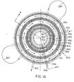
- Fig. 1A is a drawing of a bench-scale embodiment of the present invention showing a top view of the stator face with the barrier fluid flowpath illustrated by arrows, with rotor not shown.
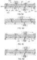
- Fig. 1B is a transverse sectional view along line AA taken through the valve of Fig. 1A and a pair of inlet and outlet fittings, showing the valve while rotating during normal operation, just as stator and rotor ports are aligned, with the right side showing the stator sump drain port.
- Fig. 2A is a drawing of the bench scale embodiment of Fig. 1 showing a top view during SIP mode of the stator port sealing ledges, with rotor not shown.
- Fig. 2B is a transverse sectional view along line BB of Fig. 2A through both inner and outer barrier/SIP stator ports.
- Figs. 3A-D are a series of sectional close-projections of the rotor and stator ports through conical planes along line CC of Fig. 1B showing the motion of the rotor ports while the rotor is traversing; process solution flow paths are also shown, as is the make-before-break aspect of the invention.
- Fig. 4 is a sectional view of the left half of the preferred embodiment of the present invention showing a pilot scale rotor carousel and stator, with all gutters and grooves also molded into the face of the elastomeric rotor diaphragm.
- Fig. 5 is a flow schematic diagram of a 5-segment carousel system illustrating the principle of SMB adsorption and separation.
- Fig. 6 is a schematic diagram of the Universal Oil Products Sorbex Cascade system for SMB continuous counterflow fractionation.
- Fig. 7 is a flow schematic diagram of an SMB size exclusion fractionation separation system similar to that of Fig. 6 with internal liquid recycle implemented on a carousel valve system according to the present invention, with components being resolved shown pictorially.
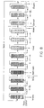
- Fig. 8 is a flow schematic diagram of an SMB ion exchange fractionation separation system with separate flowpaths for adorption, desorption and stripping implemented on a carousel valve system according to the present invention, with components being resolved shown pictorially.
- Diaphragm is used when referring to a generally elastic sealing surface that is urged against a second surface to effect a seal.
- “Dynamic wipe sealing lip” is used to refer to a specific integral construction of an elastomeric lip seal used at the sealing edge of the diaphragm.
- the lip is dynamic in that it has spring action either from a spring insert or inherently.
- Make-before-break groove is an area on either the slider or stator sealing surface that channels fluid from one channel located in the slider or stator body to another channel. It comprises a groove or ditch cut into the respective surface and terminates at one end in a port or hole that fluidly connects to the channel through the stator or slider body. Make-before-break grooves are commonly known for alleviating the pressure surges that can otherwise stress piping and pumps when fluid flowing under pressure is suddenly diverted from one conduit into another through a valve which interrupts flow continuity.
- SIP is an acronym for “sanitize-in-place", which describes the action of partially separating the sealing surfaces of the slider (or rotor) and stator and then flushing sanitizing fluid across the sealing faces of the stator and the diaphragm.
- Figs. 1-2 show plan views of the stator 300 and transverse sections through the stator and rotor 200 of a bench scale embodiment of the present invention.
- Stator 300 incorporates actuating and fluid connecting means connected to the bottom portion of stator body 301, which may be formed from ceramic material, or be machined from stainless steel, preferably 316L alloy for corrosion resistance, or from a variety of engineering plastics such as Kel F (polychlorotriflouroethylene or PCTFE), polyphenylsulfone (PPSU), polyphenylene sulfide (PPS), polythalamide (PPA), polyetheretherketone (PEEK), or other high performance materials having good resistance to abrasion and to sodium hydroxide commonly used for cleaning and SIP.
- Kel F polychlorotriflouroethylene or PCTFE
- PPSU polyphenylsulfone
- PPS polyphenylene sulfide
- PPA polythalamide
- PEEK polyetheretherketone
- the rotor 200 of this embodiment contains 12 pairs (only 1 pair being shown) of first column connection fittings 210 and second column connection fittings 212 engaging mating threads in holes in first rotor connection port 214 and second rotor connection port 215 in the top face of rotor body 201.
- Rotor body 201 is not normally wetted, thus it may be machined from aluminum or machined or molded from any high temperature engineering thermoplastic resin which will maintain integrity during brief exposure to a secondary insert molding operation at temperatures from about 48.92 to about 204.6°C (120 to about 400 °F). Suitable materials might include polysulfone, PEEK, or PPS.
- the fittings shown are commonly available, made from plastic such as polyethylene or polypropylene, with a 1/4-28 UNF thread machined or molded in. These secure the flanged ends of tubes 213, which may be fashioned from Teflon® or Tefzel® or polyethylene or polypropylene or other suitable thermoplastic tubing, and serve to provide a sanitary means to fluidly connect to the inlets and outlets of a plurality of columns mounted in a carousel attached to the rotor, which is not shown in these closeup views.
- any column or solid phase medium may be used.
- functionalized ion exchange, hydrophobic interaction, affinity, metal chelate, or size exclusion resin columns may be used to separate biomolecules such as proteins or peptides.
- Pharmaceuticals may be separated by ion exchange, chiral, or reverse phase media, etc.
- the specific type of column or media employed or molecules to be separated are not limiting.
- an elastomeric diaphragm 220 which is fashioned as an integral insert molded part of the base of rotor 200.
- Suitable materials for the diaphragm are thermoplastic elastomers such as styrene-ethylene/butylene-styrene block coploymers, for example the KRATON TM G rubbers (Shell Chemical Co. Houston, TX) such as KRATON G 2705.
- Diaphragm 220 has a first diaphragm surface 225 which is in contact with the mating bottom surface of rotor body 201, and a second diaphragm surface 226 which is in direct contact with the fluids passing through the valve, and is in selective sealing contact with portions of stator 300 as described below.
- diaphragm 220 is molded to provide hollow sleeves 223 which extend upward from first diaphragm surface 225 through rotor body 201 to terminate in integral flange gaskets 224 making sanitary sealing fluid connection to flanged column connecting tubes 213.
- Sleeves 223 are hollow, each containing a sleeve duct 227 which fluidly connects the bore of flanged column connecting tube 213 with its respective first rotor sealing port 228 or second rotor sealing port 229.
- Diaphragm 220 also includes first and second integral dynamic wipe sealing lips 221 and 222, which, along with integral flange gaskets 224, form the physical delimitation between first diaphragm surface 225 and second diaphragm surface 226.
- the dynamic wipe sealing lips have a flexible vee shape with the point angled inward toward the fluid carrying region of the valve, with the axis of the relaxed vee as molded forming an angle of between about 15 to 45 degrees, preferably 40 degrees from the plane of the stator/rotor seal, and the point of the relaxed vee as molded extending about 0.508 to 0.889 mm (0.02 to 0.035 inch), preferably 0.7112 mm (.028 inch) below the mating surface of the stator when the stator is brought into fluid sealing engagement with rotor sliding sealing ports 228 and 229.
- the resulting fully flexed sealing engagement of lips 221 and 222 when rotor 200 is sealed to stator 300 is shown in Fig. 1A as first and
- rotor body 201 When forming diaphragm 220 as an integral attachment to the base of rotor body 201 by insert molding, rotor body 201 is mounted to a mold base which has a shape to form second diaphragm surface 226 in the inner and outer circumferential limits of first diaphragm surface 225, and which has a plurality of holes at the desired positions of first and second rotor sealing ports 228 and 229. Hollow threaded plugs with ends shaped to form integral flange gaskets 224 and containing channel-forming cores of diameter to form sleeve ducts 227 are screwed into each rotor connection port 214 and 215 such that the cores engage the holes in the mold base.
- the molten thermoplastic polymer is then injected through a runner preferably located in the center of rotor body 201.
- a runner preferably located in the center of rotor body 201.
- Another embodiment of this invention would place the elastomeric diaphragm seal in the opposite orientation, i.e., instead of the diaphragm being adapted for and adhered to the rotor, it may equally be designed to function on the stator face.
- This embodiment is not shown in the drawings, but given the teachings above, one of ordinary skill in the art would be able to adapt one specific embodiment to the opposite orientation.
- the center of rotor 200 has means provided to connect to an actuator shaft 400.
- An elongated rotor drive slot 240 extends through the center of rotor 200 and loosely engages matching actuator rotating flats 410 machined into the sides of shaft 400.
- first and second rotor sealing ports 228 and 229 are caused to move while remaining in sliding sealing engagement with the respective stator first port sealing ledge 350 and second port sealing ledge 352.
- this actuation sequence is shown from an initial indexed position of each first rotor sealing port 228 at one end of its respective stator make-before-break groove 370 in Fig.
- actuator locking nut 420 is secured to the top of actuator shaft 400 by threads (not shown).
- Nut 420 has a rounded locking nut engagement shoulder 425 which bears on rotor engagement cone 250 machined into the top surface of rotor 200.
- Means for orthogonal displacement of actuator shaft 400 might include springs, pneumatic or hydraulic cylinders, or motor-driven gears.
- actuator shaft 400 When actuator shaft 400 is moved upward a controlled distance, for example 0.508 mm (0.02 inch) as seen in Fig. 2B, integral dynamic wipe sealing lips 221 and 222 are permitted to partially relax and flex downward, thereby elevating rotor 200 and permitting second diaphragm surface 226 to break sealing contact between rotor sealing ports 228 (not shown in Fig. 2B) and the mating top surface of stator 300, while maintaining stator fluid sealing contact by the tips of lips 221 and 222 as indicated schematically by the shaded regions in Fig. 2A as first and second SIP sealing zones 362 and 366.
- the orthagonal adjustability of actuator shaft 400 and rotor 200 in the present invention also permits an optimal balance of negligible loss of process fluid and maximum diaphragm life, in excess of that of the carousel column beds.
- This sealing area is represented schematically by the shaded regions 350 and 352 in Fig. 1A.
- Increased sealing force will minimize or eliminate leakage and loss of process fluid from make-before-break grooves 370 into the adjoining barrier fluid gutters described below.
- a relaxed sealing force during rotation may be programmed which permits only a minute lubricating film loss from the process streams, for example not to exceed 0.1% of the total flowrate, into the first, second and mid-barrier fluid gutters 330, 332, and 333 respectively, during the time that the rotor is being rotated as shown in Figs. 3A-D, typically 1-2 seconds every 1-5 minutes, and then operation may be returned to the maximum programmed sealing force while the rotor remains in the static indexed position.
- stator 300 has connecting ports and ducts for all fluids entering and leaving valve 100.
- a plurality of paired first connection ports 310 and second connection ports 312 may be used to program the sequence of flow through the plurality of rotor carousel beds, for example as illustrated schematically in Figs. 7 and 8.
- stator connection ports 310 are each fluidly connected to one end of a plurality of make-before-break grooves 370 spaced equally about the top surface of first and second sealing port ledges 350 and 352.
- rotor sealing ports 228 and 229 are normally in fluid tight sealing engagement with the other end of grooves 370.
- barrier fluid which might typically be sterile water for injection, enters valve 100 through first SIP/barrier connection port 320, which is mounted in the wall of stator 300 beyond the field of view. Barrier fluid flows circumferentially in both directions through first SIP/barrier gutter 330, which is a stator conduit between first SIP/barrier sealing ledge 360, first port sealing ledge 350 and second diaphragm surface 226.
- first port sealing ledge 350 This stream cleans the inner side of first port sealing ledge 350, which will preferably be operated feeding the bed inlets, since it has a smaller surface area to carry the higher pressure loads.
- barrier fluid leaves first SIP/barrier gutter 330 and enters mid barrier gutter 333 by means of first barrier gutter connection 323.
- Mid barrier gutter 333 is a stator conduit between first and second port sealing ledges 350 and 352 and second diaphragm surface 226. Barrier fluid flows circumferentially through this channel, cleaning the outer side of first port sealing ledge 350 and the inner side of second port sealing ledge 352. From there, the barrier stream passes through second barrier gutter connection 324 to enter second SIP/barrier gutter 332.
- Barrier fluid cleans the outer side of second port sealing ledge 352 and then leaves stator 300 through second SIP/barrier connection port 322, to be carried to a kill tank or other appropriate disposal means.
- the size of all the barrier channels is deliberately larger and the barrier flow deliberately slower than that of the process channels to ensure that fluid pressure in the barrier channels will always be lower than fluid pressure in the process stream grooves 370. This prevents solutes in the slowly flowing barrier stream from subsequently reentering any of the process streams.
- first and second sumps 342 and 344 are deep channels in the face of the stator which connect to sump drain port 340, which may be also plumbed to the kill tank.
- Fig. 2B depicts the means by which the valve may be aseptically cleaned and sanitized.
- all stator connection ports 310 and 312 might optionally first be flushed with a salt or other stripping buffer which is strong enough to desorb moderately tightly bound contaminants, and then a strong sanitizing agent such as 1-5 N NaOH is recirculated through all the rotor carousel beds to clean and desorb bound materials and foulants.
- actuator shaft 400 and rotor 200 are moved upward as described aboye to permit crossflushing of first and second port sealing SIP cleaning paths 351 and 353 with sanitizing agent which may be valved into barrier/SIP connection port 320.
- This cycle may then be repeated with a sterile storage buffer, and the rotor left for storage either in the elevated or relaxed rotational pressure position.
- These positions are preferred for storage, as they will prevent or minimize compression setting of the elastomeric diaphragm, which would otherwise tend to emboss the pattern of the stator gutters and grooves into second diaphragm surface 226, and to reduce the effective cross-sectional area for flow.
- FIG. 4 is a half transverse section through a pilot scale valve 600.
- valve 600 For convenience, the features of valve 600 have been numbered identically, where possible, to those of valve 100, with 500 added. For brevity, only those features which are different will be commented upon.
- First and second column connection fittings 710 and 712 are standard 3/8 inch TriClampTM sanitary tubing connectors with clamps which axially compress the flanges to make a seal against integral diaphragm elastomeric integral flange gaskets 724.
- Hollow sleeve 723 has a sleeve duct 727 with an approximate bore of 5.08 mm (0.2 inch).
- embodiments 100 and 600 The primary difference between embodiments 100 and 600 is that the larger flow channels of pilot scale valve 600, relative to the practical thickness of the diaphragm, permit first and second SIP/barrier gutters 730 and 732 and mid barrier gutter 733, and make-before break grooves 770 of valve 600 to all be molded directly into second diaphragm surface 726. This saves the cost of machining these details into the stator, as deemed necessary for the finer grooves 370 and gutters 330, 332 and 334, which have been placed on the stator to prevent loss of effective cross-sectional area over time due to wear of the diaphragm.
- the other feature included in embodiment 600 is elevating spring 930, which is needed to support the greater weight of the rotor carousel.
- spring 930 raises rotor 700 to permit unloading or cleaning of first and second port sealing ledges 850 and 852.
- the use of a spring to transmit upward displacement of actuator shaft 900 in pilot scale embodiment 600 maintains the universal joining aspects of the rotor-to-actuator shaft linkage taught for bench scale valve 100.
- Liquid chromatography is the process of separating a solute dissolved in a flowing or moving solvent from other solutes in the solvent by the differential interaction of the particular solute with a solid phase bed that is packed within a column structure. A solution of liquid phase and solute is flowed or pumped through the solid phase, and the solutes are retained and become separated based on their degree of interaction with the solid phase bed.
- Adsorption is done by flowing the feed solution through the resin bed until just before break-through (the point at which the bed is saturated and adsorbate begins to flow through the column).
- Regeneration can be done in either the same direction as the feed in the adsorption step or in the opposite direction to the feed.
- the regeneration fluid or eluent
- adsorbate adsorbed material
- Flow reversal elution is also often used for adsorption systems because the adsorbate will leave the column as a very concentrated peak.
- adsorption columns can serve as concentrators for dilute streams and may be the cheapest way to concentrate.
- the switching rate is timed to follow the MTZ, ensuring maximal loading of each bed segment, and continual supply of a freshly regenerated segment for optimal final removal from the product stream.
- the valved co-current movement of the fluid ports simulates counter-current movement of the bed, hence the name simulated moving-bed (or SMB).
- the Sorbex system employs a complex rotary valve to move feed and eluent inlets and raffinate and extract outlets cyclically along a multi-segmented column which carries a continuous recirculation of mobile phase in a direction counter to that of the simulated movement of resin caused by the intermittent rotation of the valve (see Fig. 6).
- FIGs. 7-8 a specific application of counterflow simulated moving bed liquid chromatography using a multi-port slider (rotary) valve is described.
- This separation scheme is depicted in a 12-bed rotating carousel arrangement, whereby the beds are fed by the sanitizable rotary valve previously described, and adapted to provide two inputs (eluent, feed) and two outputs (raffinate, extract), with a substantial portion of the eluent being recycled.
- Feed liquid containing both slow (represented as dots) and fast (larger circles) components is introduced at the feed port, located schematically in the middle of zones I-II (the "differential migration" zone).
- Eluent is continuously flowed in a direction counter to that of the movement of the columns.
- the slow components are carried mainly by the bed packing, typically a size exclusion-type resin, and the fast components are carried mainly by the eluent. Thus, they move in opposite directions from the feed port.
- the raffinate stream (largely comprising fast component) is taken off through the raffinate port and led to waste or solvent recapture.
- extract containing largely product slow component
- Flow rates of the inputs and outputs are controlled by pumps relative to the switching rate of the beds so as to create the separations shown in each zone.
- Fig. 8 is a schematic representation of a typical ion-exchange salt gradient separation.
- the plumbing is more complicated and requires four inputs (eluent, wash, feed, strip) and three outputs (extract, raffinate, waste).
- Feed containing the desired product and undesirable by-products and process artifacts is introduced through a feed port intermediate to zones I and II and is immediately channeled into the "slow capture" zone I. Slow components are adsorbed in zone I, and fast unbound components are swept along with the liquid to be removed as a raffinate stream.
- the carousel turns the beds pass upstream of the feed port into a wash buffer zone II.
- This wash step allows "rectification" of the slow and fast components, flushing away entrained unbound fast components from the bound slow components.
- the bound slow product continues to move with the beds past the wash inlet port into desorption zone III.
- product is desorbed by a stronger eluent, which may have a different ionic strength and/or pH, and comes off in the extract stream at the boundary of zones II and III.
- An even stronger eluent is then optionally introduced in zone IV to strip the column and desorb strongly bound species from the bed before the next adsorption cycle.
- Some stripping solution migrates into zone I with the rotation of the carousel, but this material is diluted and washed away by the raffinate stream containing unbound contaminants.
Landscapes
- Engineering & Computer Science (AREA)
- General Engineering & Computer Science (AREA)
- Mechanical Engineering (AREA)
- Chemical & Material Sciences (AREA)
- Analytical Chemistry (AREA)
- General Chemical & Material Sciences (AREA)
- Oil, Petroleum & Natural Gas (AREA)
- Chemical Kinetics & Catalysis (AREA)
- Multiple-Way Valves (AREA)
Applications Claiming Priority (3)
| Application Number | Priority Date | Filing Date | Title |
|---|---|---|---|
| US248138 | 1994-05-24 | ||
| US08/248,138 US5465748A (en) | 1994-05-24 | 1994-05-24 | Sanitizable slider diaphragm valve |
| PCT/US1995/006401 WO1995032379A1 (en) | 1994-05-24 | 1995-05-23 | Sanitizable slider diaphragm valve |
Publications (2)
| Publication Number | Publication Date |
|---|---|
| EP0760919A1 EP0760919A1 (en) | 1997-03-12 |
| EP0760919B1 true EP0760919B1 (en) | 1998-07-01 |
Family
ID=22937844
Family Applications (1)
| Application Number | Title | Priority Date | Filing Date |
|---|---|---|---|
| EP95921324A Expired - Lifetime EP0760919B1 (en) | 1994-05-24 | 1995-05-23 | Sanitizable slider diaphragm valve |
Country Status (6)
| Country | Link |
|---|---|
| US (1) | US5465748A (ja) |
| EP (1) | EP0760919B1 (ja) |
| JP (1) | JPH10501045A (ja) |
| CN (1) | CN1149333A (ja) |
| DE (1) | DE69503246T2 (ja) |
| WO (1) | WO1995032379A1 (ja) |
Families Citing this family (26)
| Publication number | Priority date | Publication date | Assignee | Title |
|---|---|---|---|---|
| US5816290A (en) * | 1996-03-13 | 1998-10-06 | Fleck Controls, Inc. | Rotary control valve for a water conditioning system |
| US6629963B2 (en) * | 1996-06-20 | 2003-10-07 | Becton, Dickinson And Company | Syringe and needle shield assembly and method of sterilizing such assembly |
| AU713590B3 (en) * | 1997-02-04 | 1999-12-09 | Philip George Doust | A sealing member and a valve closure member incorporating same |
| DE19746763C2 (de) * | 1997-10-23 | 2002-06-13 | Walter Schiffer | Membrangesteuertes Druckregelventil |
| DE19858892A1 (de) * | 1998-12-19 | 2000-06-21 | Merck Patent Gmbh | Kontinuierliches Verfahren zur Trennung von Stoffen nach Molekülgröße |
| DE10345699B3 (de) * | 2003-10-01 | 2005-04-28 | Tuchenhagen Gmbh | Verteilervorrichtung für Ventile |
| JP2008139022A (ja) * | 2005-03-23 | 2008-06-19 | Daicel Chem Ind Ltd | ブロックバルブ及びそれを有する擬似移動床式クロマトグラフィー分離装置 |
| US7789012B2 (en) * | 2005-04-25 | 2010-09-07 | Aquasyn, Llc | Valve bonnet assembly |
| US7544293B2 (en) | 2005-09-26 | 2009-06-09 | Semba Inc. | Valve and process for interrupted continuous flow chromatography |
| EP1775001A1 (en) * | 2005-10-13 | 2007-04-18 | Xendo Holding B.V. | Device for chromatographic separations |
| US7790040B2 (en) | 2006-08-30 | 2010-09-07 | Semba Biosciences, Inc. | Continuous isocratic affinity chromatography |
| US8807164B2 (en) * | 2006-08-30 | 2014-08-19 | Semba Biosciences, Inc. | Valve module and methods for simulated moving bed chromatography |
| JP5377477B2 (ja) * | 2007-05-15 | 2013-12-25 | ジーイー・ヘルスケア・バイオ−サイエンシズ・アーベー | 流れ分配弁 |
| US20090078907A1 (en) * | 2007-09-26 | 2009-03-26 | Honeywell International, Inc. | Composite valve assembly for aircraft environmental control systems |
| MX2010002630A (es) * | 2008-04-14 | 2010-05-03 | Tongaat Hulett Ltd | Aparato de distribucion giratorio que incorpora bombas interfasicas. |
| US8196603B2 (en) | 2008-08-20 | 2012-06-12 | Semba Biosciences, Inc. | Valve block assembly |
| JP5300540B2 (ja) * | 2009-03-16 | 2013-09-25 | Ckd株式会社 | 回転型切換弁及び、回転型切換弁のパージガス量の決定方法 |
| GB0906768D0 (en) * | 2009-04-21 | 2009-06-03 | Pdd Innovations Ltd | Pumps |
| US8960231B2 (en) | 2011-09-21 | 2015-02-24 | Neil Robert Picha | Multi-mode injection valve |
| CN102716609B (zh) * | 2012-06-27 | 2014-04-30 | 昆山华科膜环保科技有限公司 | 一种浓缩过滤装置 |
| US9303775B2 (en) * | 2012-12-21 | 2016-04-05 | Waters Technologies Corporation | Rotary shear valve and associated methods |
| US9399861B2 (en) | 2013-01-29 | 2016-07-26 | Zurn Industries, Llc | Diaphragm disk |
| USD787646S1 (en) | 2014-09-12 | 2017-05-23 | Zurn Industries, Llc | Flush valve diaphragm |
| US9896829B2 (en) | 2014-09-12 | 2018-02-20 | Zurn Industries, Llc | Flush valve diaphragm |
| WO2019186690A1 (ja) * | 2018-03-27 | 2019-10-03 | 株式会社島津製作所 | 水質分析計用マルチポートバルブ |
| US11713816B1 (en) | 2019-08-22 | 2023-08-01 | Colt Irrigation, LLC | Pressure loss mitigation and durable valve |
Family Cites Families (11)
| Publication number | Priority date | Publication date | Assignee | Title |
|---|---|---|---|---|
| US3240225A (en) * | 1963-01-17 | 1966-03-15 | Benjamin G Barrows | Selecting and purging apparatus |
| DE2648574C3 (de) * | 1976-10-27 | 1979-04-26 | Agfa-Gevaert Ag, 5090 Leverkusen | Umschaltvorrichtung für eine Gießvorrichtung zum Auftrag photografischer Emulsionen auf einen Schichtträger |
| US4540015A (en) * | 1983-06-30 | 1985-09-10 | Beckman Instruments, Inc. | Rotary sheer valve with wash and purge station |
| DE3326134A1 (de) * | 1983-07-20 | 1985-02-07 | Festo KG, 7300 Esslingen | Pneumatischer schrittschalter |
| US4658853A (en) * | 1985-01-09 | 1987-04-21 | Regenerative Environmental Equipment Co., Inc. | Anti-leak valving system |
| EP0205627A1 (de) * | 1985-06-11 | 1986-12-30 | OTTO TUCHENHAGEN GmbH & Co. KG | Verfahren zur Verwirklichung eines leckagefrei schaltenden und sitzreinigungsfähigen Doppelsitzventils und Vorrichtung zur Durchführung des Verfahrens |
| US4625763A (en) * | 1985-07-10 | 1986-12-02 | Uop Inc. | Disc-axial multiport valve |
| DE3825080A1 (de) * | 1988-07-23 | 1990-01-25 | Putzmeister Maschf | Vorrichtung und verfahren zum verteilen von pumpfaehigen dickstoffen in mehrere foerderleitungen |
| US4921015A (en) * | 1989-07-21 | 1990-05-01 | John Crane, Inc. | Rotary vacuum valve |
| US5311899A (en) * | 1993-02-24 | 1994-05-17 | Mitsubishi Kasei Corporation | Coupling device |
| US5375622A (en) * | 1993-12-07 | 1994-12-27 | Houston; Reagan | Multiport valve including leakage control system, particularly for a thermal regenerative fume incinerator |
-
1994
- 1994-05-24 US US08/248,138 patent/US5465748A/en not_active Expired - Lifetime
-
1995
- 1995-05-23 DE DE69503246T patent/DE69503246T2/de not_active Expired - Fee Related
- 1995-05-23 WO PCT/US1995/006401 patent/WO1995032379A1/en active IP Right Grant
- 1995-05-23 JP JP7530462A patent/JPH10501045A/ja active Pending
- 1995-05-23 EP EP95921324A patent/EP0760919B1/en not_active Expired - Lifetime
- 1995-05-23 CN CN95193270A patent/CN1149333A/zh active Pending
Also Published As
| Publication number | Publication date |
|---|---|
| JPH10501045A (ja) | 1998-01-27 |
| DE69503246T2 (de) | 1999-01-21 |
| DE69503246D1 (de) | 1998-08-06 |
| CN1149333A (zh) | 1997-05-07 |
| US5465748A (en) | 1995-11-14 |
| WO1995032379A1 (en) | 1995-11-30 |
| EP0760919A1 (en) | 1997-03-12 |
Similar Documents
| Publication | Publication Date | Title |
|---|---|---|
| EP0760919B1 (en) | Sanitizable slider diaphragm valve | |
| CN100356097C (zh) | 导液多通旋转阀 | |
| US7544293B2 (en) | Valve and process for interrupted continuous flow chromatography | |
| JP4837740B2 (ja) | クロマトグラフ分離のための装置 | |
| US6979402B1 (en) | Miniature actual moving bed assembly | |
| US8459302B2 (en) | Fluid-directing multiport rotary valve | |
| EP0086073B1 (en) | Rotary valve | |
| TWI460367B (zh) | 固定一密封片至一旋轉閥之轉子 | |
| US4632149A (en) | Rotary valve for interconnecting conduits | |
| US4625763A (en) | Disc-axial multiport valve | |
| EP0609224A1 (en) | Rotary flow control valve | |
| US7022229B1 (en) | Adsorption separation system | |
| US20090320928A1 (en) | Multi-track rotary valve in combination with a pressure reducer and method for operating the combination | |
| US7870870B2 (en) | Multiport vertical axial valve with sealing rotor | |
| JPH04131761A (ja) | 擬似移動床式液体クロマト分離装置 | |
| KR20170043358A (ko) | 입력 및 출력 흐름 별로 다수의 다중 포지션 밸브를 적용하는 smb 분리 장치 및 이를 이용한 smb 분리 방법 |
Legal Events
| Date | Code | Title | Description |
|---|---|---|---|
| PUAI | Public reference made under article 153(3) epc to a published international application that has entered the european phase |
Free format text: ORIGINAL CODE: 0009012 |
|
| 17P | Request for examination filed |
Effective date: 19961030 |
|
| AK | Designated contracting states |
Kind code of ref document: A1 Designated state(s): DE FR GB IT |
|
| 17Q | First examination report despatched |
Effective date: 19970516 |
|
| GRAG | Despatch of communication of intention to grant |
Free format text: ORIGINAL CODE: EPIDOS AGRA |
|
| GRAG | Despatch of communication of intention to grant |
Free format text: ORIGINAL CODE: EPIDOS AGRA |
|
| GRAH | Despatch of communication of intention to grant a patent |
Free format text: ORIGINAL CODE: EPIDOS IGRA |
|
| GRAH | Despatch of communication of intention to grant a patent |
Free format text: ORIGINAL CODE: EPIDOS IGRA |
|
| GRAA | (expected) grant |
Free format text: ORIGINAL CODE: 0009210 |
|
| AK | Designated contracting states |
Kind code of ref document: B1 Designated state(s): DE FR GB IT |
|
| REF | Corresponds to: |
Ref document number: 69503246 Country of ref document: DE Date of ref document: 19980806 |
|
| ET | Fr: translation filed | ||
| PLBE | No opposition filed within time limit |
Free format text: ORIGINAL CODE: 0009261 |
|
| STAA | Information on the status of an ep patent application or granted ep patent |
Free format text: STATUS: NO OPPOSITION FILED WITHIN TIME LIMIT |
|
| 26N | No opposition filed | ||
| PGFP | Annual fee paid to national office [announced via postgrant information from national office to epo] |
Ref country code: DE Payment date: 20000503 Year of fee payment: 6 |
|
| PGFP | Annual fee paid to national office [announced via postgrant information from national office to epo] |
Ref country code: FR Payment date: 20010501 Year of fee payment: 7 |
|
| PGFP | Annual fee paid to national office [announced via postgrant information from national office to epo] |
Ref country code: GB Payment date: 20010504 Year of fee payment: 7 |
|
| REG | Reference to a national code |
Ref country code: GB Ref legal event code: IF02 |
|
| PG25 | Lapsed in a contracting state [announced via postgrant information from national office to epo] |
Ref country code: DE Free format text: LAPSE BECAUSE OF NON-PAYMENT OF DUE FEES Effective date: 20020301 |
|
| PG25 | Lapsed in a contracting state [announced via postgrant information from national office to epo] |
Ref country code: GB Free format text: LAPSE BECAUSE OF NON-PAYMENT OF DUE FEES Effective date: 20020523 |
|
| GBPC | Gb: european patent ceased through non-payment of renewal fee |
Effective date: 20020523 |
|
| PG25 | Lapsed in a contracting state [announced via postgrant information from national office to epo] |
Ref country code: FR Free format text: LAPSE BECAUSE OF NON-PAYMENT OF DUE FEES Effective date: 20030131 |
|
| REG | Reference to a national code |
Ref country code: FR Ref legal event code: ST |
|
| PG25 | Lapsed in a contracting state [announced via postgrant information from national office to epo] |
Ref country code: IT Free format text: LAPSE BECAUSE OF NON-PAYMENT OF DUE FEES;WARNING: LAPSES OF ITALIAN PATENTS WITH EFFECTIVE DATE BEFORE 2007 MAY HAVE OCCURRED AT ANY TIME BEFORE 2007. THE CORRECT EFFECTIVE DATE MAY BE DIFFERENT FROM THE ONE RECORDED. Effective date: 20050523 |