EP0760768B1 - Transportsystem mit passiven fahrzeugen - Google Patents
Transportsystem mit passiven fahrzeugen Download PDFInfo
- Publication number
- EP0760768B1 EP0760768B1 EP95918651A EP95918651A EP0760768B1 EP 0760768 B1 EP0760768 B1 EP 0760768B1 EP 95918651 A EP95918651 A EP 95918651A EP 95918651 A EP95918651 A EP 95918651A EP 0760768 B1 EP0760768 B1 EP 0760768B1
- Authority
- EP
- European Patent Office
- Prior art keywords
- vehicle
- track
- tubes
- vehicles
- axis
- Prior art date
- Legal status (The legal status is an assumption and is not a legal conclusion. Google has not performed a legal analysis and makes no representation as to the accuracy of the status listed.)
- Expired - Lifetime
Links
- 230000001133 acceleration Effects 0.000 claims description 6
- LTMHDMANZUZIPE-PUGKRICDSA-N digoxin Chemical compound C1[C@H](O)[C@H](O)[C@@H](C)O[C@H]1O[C@@H]1[C@@H](C)O[C@@H](O[C@@H]2[C@H](O[C@@H](O[C@@H]3C[C@@H]4[C@]([C@@H]5[C@H]([C@]6(CC[C@@H]([C@@]6(C)[C@H](O)C5)C=5COC(=O)C=5)O)CC4)(C)CC3)C[C@@H]2O)C)C[C@@H]1O LTMHDMANZUZIPE-PUGKRICDSA-N 0.000 claims description 3
- 230000002093 peripheral effect Effects 0.000 claims description 3
- 238000012876 topography Methods 0.000 claims description 3
- 238000006073 displacement reaction Methods 0.000 claims 3
- 230000015556 catabolic process Effects 0.000 claims 1
- 230000008878 coupling Effects 0.000 claims 1
- 238000010168 coupling process Methods 0.000 claims 1
- 238000005859 coupling reaction Methods 0.000 claims 1
- 230000001771 impaired effect Effects 0.000 claims 1
- 230000001105 regulatory effect Effects 0.000 claims 1
- 230000005540 biological transmission Effects 0.000 description 7
- 125000006850 spacer group Chemical group 0.000 description 4
- 230000000694 effects Effects 0.000 description 3
- 238000006243 chemical reaction Methods 0.000 description 2
- 238000012423 maintenance Methods 0.000 description 2
- 239000003380 propellant Substances 0.000 description 2
- 238000011144 upstream manufacturing Methods 0.000 description 2
- 229910000831 Steel Inorganic materials 0.000 description 1
- 230000015572 biosynthetic process Effects 0.000 description 1
- 239000000969 carrier Substances 0.000 description 1
- 230000001419 dependent effect Effects 0.000 description 1
- 238000001514 detection method Methods 0.000 description 1
- 230000004064 dysfunction Effects 0.000 description 1
- 230000007257 malfunction Effects 0.000 description 1
- 230000000717 retained effect Effects 0.000 description 1
- 239000010959 steel Substances 0.000 description 1
- 230000001360 synchronised effect Effects 0.000 description 1
- 238000012795 verification Methods 0.000 description 1
Images

Classifications
-
- B—PERFORMING OPERATIONS; TRANSPORTING
- B61—RAILWAYS
- B61B—RAILWAY SYSTEMS; EQUIPMENT THEREFOR NOT OTHERWISE PROVIDED FOR
- B61B13/00—Other railway systems
- B61B13/12—Systems with propulsion devices between or alongside the rails, e.g. pneumatic systems
- B61B13/125—Systems with propulsion devices between or alongside the rails, e.g. pneumatic systems the propulsion device being a rotating shaft or the like
-
- B—PERFORMING OPERATIONS; TRANSPORTING
- B62—LAND VEHICLES FOR TRAVELLING OTHERWISE THAN ON RAILS
- B62D—MOTOR VEHICLES; TRAILERS
- B62D1/00—Steering controls, i.e. means for initiating a change of direction of the vehicle
- B62D1/24—Steering controls, i.e. means for initiating a change of direction of the vehicle not vehicle-mounted
- B62D1/26—Steering controls, i.e. means for initiating a change of direction of the vehicle not vehicle-mounted mechanical, e.g. by a non-load-bearing guide
- B62D1/265—Steering controls, i.e. means for initiating a change of direction of the vehicle not vehicle-mounted mechanical, e.g. by a non-load-bearing guide especially adapted for guiding road vehicles carrying loads or passengers, e.g. in urban networks for public transportation
-
- Y—GENERAL TAGGING OF NEW TECHNOLOGICAL DEVELOPMENTS; GENERAL TAGGING OF CROSS-SECTIONAL TECHNOLOGIES SPANNING OVER SEVERAL SECTIONS OF THE IPC; TECHNICAL SUBJECTS COVERED BY FORMER USPC CROSS-REFERENCE ART COLLECTIONS [XRACs] AND DIGESTS
- Y02—TECHNOLOGIES OR APPLICATIONS FOR MITIGATION OR ADAPTATION AGAINST CLIMATE CHANGE
- Y02T—CLIMATE CHANGE MITIGATION TECHNOLOGIES RELATED TO TRANSPORTATION
- Y02T30/00—Transportation of goods or passengers via railways, e.g. energy recovery or reducing air resistance
Definitions
- the invention relates to a transport system by passive vehicles, of the type described in the preamble to the claim 1.
- the object of the present invention is to propose a system transport of the type indicated above, which overcomes the disadvantages of the state of the art.
- the transfer system according to the invention comprises the characteristics indicated in the characterizing part of claim 1.
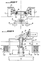
- Figure 1 shows part of a track 1 on which a vehicle 2 moves in particular for the transport of passengers, of which only the two bogies 3 carriers of two wheels 4 and the lower part with two propulsion motor devices 5 and two devices guide 6 each associated with a bogie are shown.
- Track 1 includes a trench 8 which has two parallel side surfaces 9, located opposite and extending substantially parallel to the axis of the track, symmetrically with respect to the median vertical plane longitudinal of the latter. Each of the two faces is adapted to constitute a guide face for vehicles traveling on the track.
- the lower part of the trench comprises two inclined faces 10 in the form of branches of a V which join up one of the faces vertical side 9 and bottom horizontal bottom 11 of the trench.
- the trench is covered at ground level by two plates 15 leaving between them a slot extending in the axis of the trench. Wheels 4 move on tracks 7 provided on the ground on either side of the trench.
- a series of rotating tubes 13 which are axially aligned.
- the tubes are mounted on tapered bearings at the end of so as to ensure their maintenance in all axes. Sure the whole track they are placed on bearings arranged at regular intervals of for example 4 meters.
- the tubes are made of steel with a diameter of 244 mm for a thickness of 6.3 mm.
- the tubes are driven, in one direction of rotation, at a speed constant of for example of the order of 800 revolutions / minute.
- the continuation of the tubes is divided into sections and the motors drive in rotation of the sections are different powers depending on the nature and length of sections. For example we can provide motors acceleration and slopes, capable of setting 80 meter tube rotation and maintenance motors constant speed, capable of rotating 120 meters of tube.
- Torque transmission can be carried out from any appropriately known per se, for example using a toothed belt, engaged with a gear motor in relation to the characteristics of the engine.
- a toothed belt engaged with a gear motor in relation to the characteristics of the engine.
- the rotational drive motors of tube sections are not shown.
- a standby motor 12 arranged between two sections of tubes, so as to ensure the setting in rotation of one or the other contiguous section.
- the torque transmission device which is of the toothed belt type.
- each device guide 6 is made in the form of a platform 16 fixed ascent under a bogie 3 via a spacer 17 in the form of a plate extending vertically through the gap between the two decks 15 covering the trench 8.
- the platform thus lying inside the trench comprises two pairs of guide rollers 19 with axes of vertical rotation, each pair being arranged so to be in abutment against one of the guide surfaces vertical 9 of the track. Between the two rollers 19 of each pair is fitted with an emergency brake indicated in 20.
- the two bogies 3 of the vehicle are connected by a longitudinal beam 22 which is articulated to each of its ends at 23 on a platform 16. The beam thus extends axially in the trench 8, like this is shown in figure 2.
- This same figure shows although the chassis of the vehicle identified by 25 is rotatably mounted around a vertical axis on each bogie 3, using two crowns 26, 27 respectively integral with the chassis and the bogie.
- the connecting beam 22 carries the two devices thrusters 5, each arranged near a bogie in the axial space between them.
- Each propulsion device 5 comprises a roller friction contact propellant motor 30 with axis 31 is housed in a support in the form of a fork 32 in the form a vertically oriented U at the base of which is fixed a rod 33 which is integral in rotation at its end free to a pinion 34 meshing with a return pinion 35 to horizontal axis mounted integral in rotation by via a declutching device 36 of the output shaft of an electric motor 37 produced under form of a stepper motor.
- Rod 33 is mounted rotatable and retained axially using a collar 38 in a support 40 mounted vertically displaceable on the beam 22.
- the support 40 has an upper platform horizontal 41 whose central area is configured in housing part 42 of the collar 38 of the rod 33.
- the rectangular platform 41 door at each of its angles a vertical spacer 43. Thanks to its spacers the support 40 is mounted astride the beam 22, so as to prohibit the support any other movement than vertical.
- the mounting of the support on the beam provides a lateral guiding effect for the support.
- the ends of the two spacers located at each longitudinal end of the support 40 carry a platform horizontal 44 which extends outwards from the support 40 in the axis of the vehicle.
- a spring helical 46 Between each platform 44 and the connecting beam 22 is placed a spring helical 46 whose axis extends vertically. This spring has the purpose of pushing the propellant roller 30 against the outer peripheral surface of the tube turning engine 13, as we can clearly see on the figure 3.
- any rotation of the output shaft of the stepping motor 37 causes a pivoting in direction of arrow F of the roller and thus a variation the orientation of the axis of rotation 31 of the roller by relative to the axis of the tube. Since the pebble is pushed by the springs 46 against the tube 13, the rotation of the latter is transmitted by friction to the roller which then causes the vehicle to move at a speed which depends on the orientation of the roller relative to the tube.
- a single stepper motor step 37 is sufficient to ensure the synchronous orientation of the two drive rollers 30.
- This effect is obtained thanks to a connection between the rods 33, in the example shown produced in the form of a parallelogram 48 comprising two rods 49 which are parallel to the axis of the vehicle and connected by two connecting rods 50 each of which is fixed integrally in rotation, in its part central, to the rod 33 for orienting a roller 30, of the illustrated in FIG. 3.
- the movement of rotation imparted to the rod 31 of one of the rollers is passed on to each other's rod.
- dynamos 52 are mounted on axes 31 of rollers 30, which are part of an autonomous device electric power supply to the vehicle.
- each end of the vehicle is provided with a connection 53 to another vehicle which is articulated to one end of a rod 55 the other end of which is articulated at an angle to the parallelogram 49.
- the vehicles according to the invention are ordered from fully automatic.
- the system according to the invention comprises a central control station (not shown), which manages all of the vehicles.
- this post can accomplish this task, the way is confined to sectors each of which is equipped with a loop transmitter and receiver of control and regulation.
- Each vehicle is equipped with a transceiver device which allows him to communicate with the central station, by through a control loop and regulation.
- the vehicle transmits a message to the central station identification and status parameters of the different vehicle equipment components.
- the vehicle receives speed setpoint for sector following.
- the setpoint is accompanied by a variable indicating the type of variation curves acceleration to be observed, defined by the course management.
- Two variation curves are memorized for each sector, namely the curve standard acceleration and deceleration, especially in depending on the topography or the geometry of the track in this sector and an emergency deceleration curve. These curves are stored in a part of the device vehicle transceiver, which constitute the interface with the stepper motor. This part is designed to monitor the proper functioning of the vehicle and to detect any bad data transmission.
- the mouths preceding that which gave the instruction to speed and is identifiable by the central station thanks to the vehicle identification message emit, on central station control, variation information from for example 5 to 0 km / hours for the first mouth (for example 40 m away), 30 to 5 km / hour for the second mouth (located at 80 m), from 43 to 30 km / hour for the third mouth (located for example at 120 m), and keep the speed of 43 km / hour for the fourth loop (located 160 m).
- a safety loop is provided upstream of the vehicle passage.
- the mouths that just stated will be counted from that security mouth. Since the normal deviation between two vehicles is 200 meters in this example, corresponding to 5 sectors, the instructions of slowdown only take effect in the event of a dysfunction.
- the information transmitted evolves in this way depending on the detected presence of vehicles, by managing the four vents located in upstream.
- the collection and transmission of information call to data concentrators distributed along the way.
- Track-vehicle communications are secure by transmission verification protocols data.
- Central station IT centralizes kinematics data, specific to each vehicle. When of the passage over a mouth at a time t, knowing the speed and distance to the next mouth, the central station calculates the journey time tp and establishes thus predicting the presence of the vehicle at the moment t + tp in the mouth area of the next sector.
- the central station When the vehicle passes over the next mouth at the expected time instant, detectable by the emission of its identification message, the central station notices the nominality of the route of this vehicle. If on the other hand the identification message does not reach the station central at the scheduled time, this concludes that there is a malfunction and implements the mode degraded operation which will be described later.
- next vehicle is put into slow speed and mates mechanically with the broken down vehicle.
- the two vehicles move at speed reduced to the next station where descends all passengers.
- the two empty vehicles are then routed at normal speed to the garage workshop.
- the parallelogram ensures the positioning of the rollers of the broken down vehicle on the rollers position of the pusher vehicle.
- the vehicle In the case of a bad transmission or a erroneous transmission of information from loops or anomaly detection on board the vehicle, the vehicle goes into safety providing a vehicle emergency stop, engine disengaging not, which puts the operation in degraded mode.
Landscapes
- Engineering & Computer Science (AREA)
- Chemical & Material Sciences (AREA)
- Combustion & Propulsion (AREA)
- Transportation (AREA)
- Mechanical Engineering (AREA)
- Platform Screen Doors And Railroad Systems (AREA)
- Chain Conveyers (AREA)
- Automobile Manufacture Line, Endless Track Vehicle, Trailer (AREA)
- Electric Propulsion And Braking For Vehicles (AREA)
- Refuse Collection And Transfer (AREA)
- Rollers For Roller Conveyors For Transfer (AREA)
- Control Of Driving Devices And Active Controlling Of Vehicle (AREA)
Claims (12)
- System zum Transport durch passive Fahrzeuge, derjenigen Gattung, bei welcher die Fahrzeuge sich mit Hilfe von Rädern (4) auf Rollwegen (7) einer Bahn (1) bewegen, welches als die Fahrbewegung des Fahrzeuges gewährleistende Mittel, eine Reihenfolge von in der Längsrichtung der Bahn (1) angeordneten Drehrohren (13) und Mittel zur Führung der Fahrzeuge entlang dieser letzteren aufweist, wobei jedes Fahrzeug (2) wenigstens eine eine Rolle (30) zum Fahrantrieb des Fahrzeuges durch Reibungsberührung mit der äußeren Umfangsfläche der Drehrohre (13), dessen Drehachse in bezug auf die Achse der Rohre durch Schwenken um eine vorteilhaft etwa senkrechte Achse zwischen einer mit den Rohren gleichgerichteten Stellung, in welcher die Rollen das Fahrzeug nicht zum Fahren antreiben und eine maximale Fahrantriebstellung richtungseinstellbar ist und wenigstens eine zur Zusammenwirkung mit den Führungsmitteln der Bahn angepaßte Vorrichtung (6) zur Führung des Fahrzeuges aufweist, dadurch gekennzeichnet, daß die Führungsmittel der Bahn (1) durch zwei Seitenflächen (9) eines mit Ausnahme eines Schlitzes in der Höhe der Bahn (1) (bei 15) abgedeckten Einschnitts (8) gebildet werden, daß die Führungsvorrichtung (6) sich innerhalb des Einschnitts befindet und sich an den Führungsflächen (9) abstützende und an einem fest verbundenen Träger (16) angeordnete Räder (19) aufweist, daß ein Fahrzeug wenigstens zwei Räder (4) tragende Fahrgestelle umfaßt und daß eine Führungsvorrichtung (6) jedem Fahrgestell (3) zugeordnet ist, daß die Träger (16) an einem die Halterung der Fahrantriebsvorrichtungen bildenden Balken (22) angelenkt sind und daß jeder Träger (16) der Führungsräder mit den Fahrgestellen durch den besagten Schlitz durchsetzende Stege (17) verbunden ist.
- System nach Anspruch 1, dadurch gekennzeichnet, daß die Vorrichtung (5) zur Ausrichtung einer Fahrantriebsrolle (30) durch einen elektrischen Schrittschaltmotor (37) gebildet wird.
- System nach einem der Ansprüche 1 und 2, dadurch gekennzeichnet, daß jede Fahrantriebsrolle (5) in einem eine Stange (33) tragenden Halter (32) drehbar gelagert ist, welche Stange sich senkrecht zur Achse (31) der Rolle erstreckt und in einem an dem Verbindungsbalken (22) angeordneten Halter (40) drehbar gelagert ist, um nur eine senkrechte Bewegung entgegen zum Inberührungbringen der Rolle mit der Umfangsfläche der Drehrohre (13) durch Schieben angepaßten Rückstellmitteln (46) durchführen zu können, wobei die Stange (33) fähig ist, durch den elektrischen Schrittschaltmotor (37) zum Drehen angetrieben zu werden.
- System nach Anspruch 3, dadurch gekennzeichnet, daß Dynamomaschinen (52) an der Achse (31) der Fahrantriebsrolle (30), die einen Teil einer Vorrichtung zur selbsttätigen Speisung des Fahrzeuges mit elektrischer Energie bilden, angeordnet sind.
- System nach Anspruch 3 oder 4, dadurch gekennzeichnet, daß das Fahrzeug zwei Fahrantriebsrollen (5) umfaßt, deren Ausrichtung in bezug auf die Achse der Rohre (13) durch einen einzigen Schrittschaltmotor (37) über eine Verbindung in der Gestalt eines verformbaren Parallelogrammes (49) gesteuert wird.
- System nach einem der vorangehenden Ansprüche, dadurch gekennzeichnet, daß es einen zum Dialog mit einer sich in jedem Fahrzeug befindenden Sender-Emfänger-Vorrichtung angepaßten Zentralsteuerstand umfaßt und die Bahn (1) in Sektoren unterteilt ist, wobei jedem Sektor eine Sollgeschwindigkeit in Abhängigkeit von der Topographie des Bahnsektors und gegebenenfalls von der Lage in bezug auf das vorangehende Fahrzeug zugeteilt ist.
- System nach Anspruch 6, dadurch gekennzeichnet, daß jeder Sektor eine mit dem Zentralstand verbundene Sendungs-Empfangsschleife zur Kontrolle und Regelung umfaßt, die bestimmt ist, den Dialog mit der Sender-Empfängervorrichtung der Fahrzeuge zu gewährleisten.
- System nach Anspruch 7, dadurch gekennzeichnet, daß der Zentralstand angepaßt ist, um für jedes Fahrzeug, den Zeitpunkt der Durchfahrt jedes Bahnabschnitts zu berechnen und die normale Bewegung der Fahrzeuge durch Vergleich der berechneten Durchfahrtzeit mit der durch die Sender-Empfängervorrichtung des nachzuprüfenden Fahrzeuges gemeldeten tatsächlichen Durchfahrtzeit zu überprüfen.
- System nach einem der Ansprüche 6 bis 8, dadurch gekennzeichnet, daß jedes Fahrzeug angepaßt ist, um einen Geschwindigkeitssollwert für jeden nachfolgenden Sektor aufzunehmen, wobei dieser Wert von einer die Gattung von einzuhaltenden Beschleunigungsänderungskurven angebenden Veränderlichen begleitet ist.
- System nach Anspruch 9, dadurch gekennzeichnet, daß die beiden Änderungskurven für jede Kurve einer Standartbeschleunigungs- und verzögerungskurve insbesondere in Abhängikeit von der Topographie oder der Geometrie der Bann in diesem Sektor und einer Notverzögerungskurve gespeichert werden.
- System gemäß Anspruch 10, dadurch gekennzeichnet, daß im Falle einer Anomalie wie eines Versagens, das Fahrzeug sich in einen ein Notanhalten des Fahrzeuges vorsehenden Sicherheitszustand versetzt und daß eine Betriebsweise im verdorbenen Vorgang für das nachfolgende Fahrzeug vorgesehen ist, die die Ankupplung des letzteren an das ausgefallene Fahrzeug und die gemeinsame Fahrtbewegung der beiden Fahrzeuge bei einer verringerten Geschwindigkeit bis zur nächsten normalen Haltestelle gewährleistet.
- System nach einem der vorangehenden Ansprüche, dadurch gekennzeichnet, daß die Fahrantriebsrollen (5) angepaßt sind, um selbsttätig in eine zu den Rohren senkrechte Stellung automatisch zurückzukommen, sobald der Betrieb des Schrittschaltmotors (37) ausgeschaltet worden ist, wobei dieser Motor angepaßt ist, um die Ausrichtung der Rollen zu betätigen und diese in dieser Stellung zu halten.
Applications Claiming Priority (3)
| Application Number | Priority Date | Filing Date | Title |
|---|---|---|---|
| FR9405273 | 1994-04-29 | ||
| FR9405273A FR2719277B1 (fr) | 1994-04-29 | 1994-04-29 | Système de transport par véhicules passifs. |
| PCT/FR1995/000554 WO1995029834A1 (fr) | 1994-04-29 | 1995-04-27 | Systeme de transport par vehicules passifs |
Publications (2)
| Publication Number | Publication Date |
|---|---|
| EP0760768A1 EP0760768A1 (de) | 1997-03-12 |
| EP0760768B1 true EP0760768B1 (de) | 1999-01-27 |
Family
ID=9462710
Family Applications (1)
| Application Number | Title | Priority Date | Filing Date |
|---|---|---|---|
| EP95918651A Expired - Lifetime EP0760768B1 (de) | 1994-04-29 | 1995-04-27 | Transportsystem mit passiven fahrzeugen |
Country Status (7)
| Country | Link |
|---|---|
| US (1) | US5953995A (de) |
| EP (1) | EP0760768B1 (de) |
| AT (1) | ATE176206T1 (de) |
| AU (1) | AU2449595A (de) |
| DE (1) | DE69507612T2 (de) |
| FR (1) | FR2719277B1 (de) |
| WO (1) | WO1995029834A1 (de) |
Families Citing this family (10)
| Publication number | Priority date | Publication date | Assignee | Title |
|---|---|---|---|---|
| ITMI20020786A1 (it) * | 2002-04-12 | 2003-10-13 | Sandvik Sorting Systems S P A | Dispositivo per trasferire energia meccanica a bordo di un treno di carrelli di una macchina smistatrice |
| US6810306B1 (en) | 2002-10-07 | 2004-10-26 | Storage Technology Corporation | Data storage library status monitoring |
| US6741182B1 (en) | 2002-10-07 | 2004-05-25 | Storage Technology Corporation | Automated storage library brush failure detection |
| US6698359B1 (en) * | 2002-10-07 | 2004-03-02 | Storage Technology Corporation | Data storage library rail anomaly recovery |
| US6840360B1 (en) | 2002-10-07 | 2005-01-11 | Storage Technology Corporation | Automated storage library power strip fault detection |
| US7184238B1 (en) | 2002-10-07 | 2007-02-27 | Storage Technology Corporation | Track impedance anomaly detection in an automated data storage library |
| US6885911B1 (en) | 2002-10-07 | 2005-04-26 | Storage Technology Corporation | Track anomaly detection in an automated data storage library |
| EP1977292A2 (de) | 2006-01-17 | 2008-10-08 | Gulfstream Aerospace Corporation | System und verfahren für ein integriertes backup-steuerungssystem |
| US7814839B2 (en) * | 2007-01-08 | 2010-10-19 | OCS Intellitrak, Inc. | Inverted conveyor |
| US10279823B2 (en) * | 2016-08-08 | 2019-05-07 | General Electric Company | System for controlling or monitoring a vehicle system along a route |
Family Cites Families (12)
| Publication number | Priority date | Publication date | Assignee | Title |
|---|---|---|---|---|
| US3077165A (en) * | 1959-04-11 | 1963-02-12 | Pirelli | Vehicle guide means |
| US3356040A (en) * | 1964-05-11 | 1967-12-05 | Borgs Fabriks Ab | Device for conveyor systems |
| GB1095414A (de) * | 1964-09-22 | 1900-01-01 | ||
| FR2036543A5 (de) * | 1969-03-27 | 1970-12-24 | Alsthom | |
| FR2126797A5 (de) * | 1971-02-08 | 1972-10-06 | Toyo Kogyo Co | |
| US4593623A (en) * | 1984-04-10 | 1986-06-10 | Heico Inc. | Reversible, accumulating longitudinal drive tube carrier |
| CH667241A5 (en) * | 1985-03-11 | 1988-09-30 | Oskar Schlaepfer | Current supply system for electric train or tram - uses auxiliary carriage running along supply line channel with carriage movement used for tram steering control |
| US4766547A (en) * | 1986-04-14 | 1988-08-23 | Transfer Technologies, Inc. | Computer controlled conveyor system |
| FR2599694B1 (fr) * | 1986-06-05 | 1990-08-24 | Critt Productique | Systeme de transport par vehicules passifs |
| US4825135A (en) * | 1987-11-17 | 1989-04-25 | Hypermotion, Inc. | Method and apparatus for providing mechanical amplification |
| US4922831A (en) * | 1988-06-29 | 1990-05-08 | Heico Inc. | Lightweight car-on-track system |
| FR2690120B1 (fr) * | 1992-04-21 | 1997-01-24 | Treviso Marc Pierre | Systeme de transport a vehicules passifs. |
-
1994
- 1994-04-29 FR FR9405273A patent/FR2719277B1/fr not_active Expired - Fee Related
-
1995
- 1995-04-27 EP EP95918651A patent/EP0760768B1/de not_active Expired - Lifetime
- 1995-04-27 AU AU24495/95A patent/AU2449595A/en not_active Abandoned
- 1995-04-27 DE DE69507612T patent/DE69507612T2/de not_active Expired - Fee Related
- 1995-04-27 US US08/732,370 patent/US5953995A/en not_active Expired - Fee Related
- 1995-04-27 AT AT95918651T patent/ATE176206T1/de not_active IP Right Cessation
- 1995-04-27 WO PCT/FR1995/000554 patent/WO1995029834A1/fr not_active Ceased
Also Published As
| Publication number | Publication date |
|---|---|
| DE69507612T2 (de) | 1999-09-09 |
| FR2719277A1 (fr) | 1995-11-03 |
| FR2719277B1 (fr) | 1996-06-21 |
| EP0760768A1 (de) | 1997-03-12 |
| ATE176206T1 (de) | 1999-02-15 |
| AU2449595A (en) | 1995-11-29 |
| US5953995A (en) | 1999-09-21 |
| WO1995029834A1 (fr) | 1995-11-09 |
| DE69507612D1 (de) | 1999-03-11 |
Similar Documents
| Publication | Publication Date | Title |
|---|---|---|
| EP0760768B1 (de) | Transportsystem mit passiven fahrzeugen | |
| CA2378636C (fr) | Procede et dispositif de pilotage de l'alimentation en energie electrique d'un vehicule a traction electrique destine a fonctionner en mode d'alimentation externe ou en mode d'alimentation autonome | |
| FR2686743A1 (fr) | Dispositif d'enroulement et de deroulement d'un cable de transport d'energie, ou analogue. | |
| EP0114139B1 (de) | Vorrichtung zur Prüfung von bogenförmigen Röhren mit einer durch Luft angetriebenen Sonde | |
| EP0018932B1 (de) | Drahtseilbahn-Transportvorrichtung mit doppeltem Umlaufseil und veränderlicher Geschwindigkeit | |
| EP0581675A1 (de) | Anordnung einer zwischen zwei Lagen schwenkbaren Vorrichtung, zum Beispiel eine Schranke, die zwischen einer den Zugang zu einem Gebiet versperrenden Lage und einer diesen Zugang freigebenden Lage verschwenkbar ist | |
| FR2546454A1 (fr) | Vehicule de travail autopropulse | |
| CH647467A5 (fr) | Transporteur a cable aerien. | |
| EP0351777B1 (de) | Vorrichtung zum automatischen Aufwickeln eines Kabels oder Drahtes auf einer Haspel | |
| EP0907541B1 (de) | Transporteinrichtung mit optischer und mechanischer führung | |
| EP3862062B1 (de) | Mobile untergruppe zur aufnahme und beförderung mindestens eines fahrgastes und entsprechende vergnügungsanlage | |
| EP0050891A1 (de) | Windmotor | |
| CA2542883C (fr) | Systeme de transport par gravite de vehicules sur rail | |
| WO1981001229A1 (fr) | Appareil d'arrosage automatique a bobine porte-tuyau axial, et deplacement alterne | |
| WO1987007572A1 (fr) | Systeme de transport par vehicules passifs | |
| EP3877070B1 (de) | Bewegliche unterbaugruppe zum aufnehmen und fördern von mindestens einem passagier und zugehörige anreizeinrichtung | |
| FR2654052A1 (fr) | Procede pour la mise en route et l'arret d'une installation de transport aerien par cable. | |
| EP3934959B1 (de) | Kabelfahrzeug-transportanlage und verfahren zum messen einer information bezüglich einer solchen anlage | |
| EP0297007B1 (de) | Vorrichtung zur Drehkraftabnahme an Kraftfahrzeugen | |
| EP3862063B1 (de) | Mobile untergruppe zur aufnahme und beförderung mindestens eines fahrgastes, entsprechende vergnügungsanlage und ihr steuerungsverfahren | |
| EP0933277B1 (de) | Antriebsmechanismus eines Transportsystems mit Kabeln, der ein Antriebsrad mit doppelter Umschlingung aufweist | |
| FR2890929A1 (fr) | Procede et dispositif de controle d'un organe de freinage ou de mise en mouvement auxiliaire pour installation de transport a cable | |
| EP2891822A2 (de) | Leistungsübertragungsvorrichtung | |
| FR2512326A1 (fr) | Vehicule pour le taillage des arbres fruitiers | |
| FR2857631A1 (fr) | Dispositif de generation d'un moment de lacet sur un vehicule automobile |
Legal Events
| Date | Code | Title | Description |
|---|---|---|---|
| PUAI | Public reference made under article 153(3) epc to a published international application that has entered the european phase |
Free format text: ORIGINAL CODE: 0009012 |
|
| 17P | Request for examination filed |
Effective date: 19961202 |
|
| AK | Designated contracting states |
Kind code of ref document: A1 Designated state(s): AT BE CH DE DK ES FR GB GR IE IT LI LU NL PT SE |
|
| 17Q | First examination report despatched |
Effective date: 19970307 |
|
| GRAG | Despatch of communication of intention to grant |
Free format text: ORIGINAL CODE: EPIDOS AGRA |
|
| GRAG | Despatch of communication of intention to grant |
Free format text: ORIGINAL CODE: EPIDOS AGRA |
|
| GRAH | Despatch of communication of intention to grant a patent |
Free format text: ORIGINAL CODE: EPIDOS IGRA |
|
| GRAH | Despatch of communication of intention to grant a patent |
Free format text: ORIGINAL CODE: EPIDOS IGRA |
|
| GRAA | (expected) grant |
Free format text: ORIGINAL CODE: 0009210 |
|
| AK | Designated contracting states |
Kind code of ref document: B1 Designated state(s): AT BE CH DE DK ES FR GB GR IE IT LI LU NL PT SE |
|
| PG25 | Lapsed in a contracting state [announced via postgrant information from national office to epo] |
Ref country code: SE Free format text: THE PATENT HAS BEEN ANNULLED BY A DECISION OF A NATIONAL AUTHORITY Effective date: 19990127 Ref country code: NL Free format text: LAPSE BECAUSE OF FAILURE TO SUBMIT A TRANSLATION OF THE DESCRIPTION OR TO PAY THE FEE WITHIN THE PRESCRIBED TIME-LIMIT Effective date: 19990127 Ref country code: IT Free format text: LAPSE BECAUSE OF FAILURE TO SUBMIT A TRANSLATION OF THE DESCRIPTION OR TO PAY THE FEE WITHIN THE PRE;WARNING: LAPSES OF ITALIAN PATENTS WITH EFFECTIVE DATE BEFORE 2007 MAY HAVE OCCURRED AT ANY TIME BEFORE 2007. THE CORRECT EFFECTIVE DATE MAY BE DIFFERENT FROM THE ONE RECORDED.SCRIBED TIME-LIMIT Effective date: 19990127 Ref country code: GR Free format text: LAPSE BECAUSE OF NON-PAYMENT OF DUE FEES Effective date: 19990127 Ref country code: GB Free format text: LAPSE BECAUSE OF NON-PAYMENT OF DUE FEES Effective date: 19990127 Ref country code: ES Free format text: THE PATENT HAS BEEN ANNULLED BY A DECISION OF A NATIONAL AUTHORITY Effective date: 19990127 Ref country code: AT Free format text: LAPSE BECAUSE OF FAILURE TO SUBMIT A TRANSLATION OF THE DESCRIPTION OR TO PAY THE FEE WITHIN THE PRESCRIBED TIME-LIMIT Effective date: 19990127 |
|
| REF | Corresponds to: |
Ref document number: 176206 Country of ref document: AT Date of ref document: 19990215 Kind code of ref document: T |
|
| REG | Reference to a national code |
Ref country code: CH Ref legal event code: EP |
|
| REG | Reference to a national code |
Ref country code: IE Ref legal event code: FG4D Free format text: FRENCH |
|
| REF | Corresponds to: |
Ref document number: 69507612 Country of ref document: DE Date of ref document: 19990311 |
|
| PG25 | Lapsed in a contracting state [announced via postgrant information from national office to epo] |
Ref country code: PT Free format text: LAPSE BECAUSE OF FAILURE TO SUBMIT A TRANSLATION OF THE DESCRIPTION OR TO PAY THE FEE WITHIN THE PRESCRIBED TIME-LIMIT Effective date: 19990427 Ref country code: LU Free format text: LAPSE BECAUSE OF NON-PAYMENT OF DUE FEES Effective date: 19990427 Ref country code: DK Free format text: LAPSE BECAUSE OF FAILURE TO SUBMIT A TRANSLATION OF THE DESCRIPTION OR TO PAY THE FEE WITHIN THE PRESCRIBED TIME-LIMIT Effective date: 19990427 |
|
| PG25 | Lapsed in a contracting state [announced via postgrant information from national office to epo] |
Ref country code: LI Free format text: LAPSE BECAUSE OF NON-PAYMENT OF DUE FEES Effective date: 19990430 Ref country code: CH Free format text: LAPSE BECAUSE OF NON-PAYMENT OF DUE FEES Effective date: 19990430 Ref country code: BE Free format text: LAPSE BECAUSE OF NON-PAYMENT OF DUE FEES Effective date: 19990430 |
|
| NLV1 | Nl: lapsed or annulled due to failure to fulfill the requirements of art. 29p and 29m of the patents act | ||
| GBV | Gb: ep patent (uk) treated as always having been void in accordance with gb section 77(7)/1977 [no translation filed] |
Effective date: 19990127 |
|
| PG25 | Lapsed in a contracting state [announced via postgrant information from national office to epo] |
Ref country code: IE Free format text: LAPSE BECAUSE OF NON-PAYMENT OF DUE FEES Effective date: 19990820 |
|
| REG | Reference to a national code |
Ref country code: IE Ref legal event code: FD4D |
|
| BERE | Be: lapsed |
Owner name: SAILLANT YVES CLAUDE DANIEL Effective date: 19990430 Owner name: MOURER JEAN-CLAUDE Effective date: 19990430 Owner name: TREVISO MARC Effective date: 19990430 |
|
| PLBE | No opposition filed within time limit |
Free format text: ORIGINAL CODE: 0009261 |
|
| STAA | Information on the status of an ep patent application or granted ep patent |
Free format text: STATUS: NO OPPOSITION FILED WITHIN TIME LIMIT |
|
| REG | Reference to a national code |
Ref country code: CH Ref legal event code: PL |
|
| PG25 | Lapsed in a contracting state [announced via postgrant information from national office to epo] |
Ref country code: FR Free format text: LAPSE BECAUSE OF NON-PAYMENT OF DUE FEES Effective date: 19991231 |
|
| 26N | No opposition filed | ||
| REG | Reference to a national code |
Ref country code: FR Ref legal event code: ST |
|
| PGFP | Annual fee paid to national office [announced via postgrant information from national office to epo] |
Ref country code: DE Payment date: 20050506 Year of fee payment: 11 |
|
| PG25 | Lapsed in a contracting state [announced via postgrant information from national office to epo] |
Ref country code: DE Free format text: LAPSE BECAUSE OF NON-PAYMENT OF DUE FEES Effective date: 20061101 |