EP0760628B1 - Angioplasty catheter system - Google Patents
Angioplasty catheter system Download PDFInfo
- Publication number
- EP0760628B1 EP0760628B1 EP95919832A EP95919832A EP0760628B1 EP 0760628 B1 EP0760628 B1 EP 0760628B1 EP 95919832 A EP95919832 A EP 95919832A EP 95919832 A EP95919832 A EP 95919832A EP 0760628 B1 EP0760628 B1 EP 0760628B1
- Authority
- EP
- European Patent Office
- Prior art keywords
- shaft
- printed circuit
- catheter system
- conductor
- balloon
- Prior art date
- Legal status (The legal status is an assumption and is not a legal conclusion. Google has not performed a legal analysis and makes no representation as to the accuracy of the status listed.)
- Expired - Lifetime
Links
Images


Classifications
-
- A—HUMAN NECESSITIES
- A61—MEDICAL OR VETERINARY SCIENCE; HYGIENE
- A61M—DEVICES FOR INTRODUCING MEDIA INTO, OR ONTO, THE BODY; DEVICES FOR TRANSDUCING BODY MEDIA OR FOR TAKING MEDIA FROM THE BODY; DEVICES FOR PRODUCING OR ENDING SLEEP OR STUPOR
- A61M25/00—Catheters; Hollow probes
- A61M25/10—Balloon catheters
- A61M25/104—Balloon catheters used for angioplasty
-
- A—HUMAN NECESSITIES
- A61—MEDICAL OR VETERINARY SCIENCE; HYGIENE
- A61B—DIAGNOSIS; SURGERY; IDENTIFICATION
- A61B17/00—Surgical instruments, devices or methods
- A61B17/22—Implements for squeezing-off ulcers or the like on inner organs of the body; Implements for scraping-out cavities of body organs, e.g. bones; for invasive removal or destruction of calculus using mechanical vibrations; for removing obstructions in blood vessels, not otherwise provided for
-
- A—HUMAN NECESSITIES
- A61—MEDICAL OR VETERINARY SCIENCE; HYGIENE
- A61B—DIAGNOSIS; SURGERY; IDENTIFICATION
- A61B17/00—Surgical instruments, devices or methods
- A61B17/32—Surgical cutting instruments
- A61B17/3205—Excision instruments
- A61B17/3207—Atherectomy devices working by cutting or abrading; Similar devices specially adapted for non-vascular obstructions
- A61B17/320725—Atherectomy devices working by cutting or abrading; Similar devices specially adapted for non-vascular obstructions with radially expandable cutting or abrading elements
-
- A—HUMAN NECESSITIES
- A61—MEDICAL OR VETERINARY SCIENCE; HYGIENE
- A61B—DIAGNOSIS; SURGERY; IDENTIFICATION
- A61B18/00—Surgical instruments, devices or methods for transferring non-mechanical forms of energy to or from the body
- A61B18/04—Surgical instruments, devices or methods for transferring non-mechanical forms of energy to or from the body by heating
- A61B18/08—Surgical instruments, devices or methods for transferring non-mechanical forms of energy to or from the body by heating by means of electrically-heated probes
-
- A—HUMAN NECESSITIES
- A61—MEDICAL OR VETERINARY SCIENCE; HYGIENE
- A61B—DIAGNOSIS; SURGERY; IDENTIFICATION
- A61B18/00—Surgical instruments, devices or methods for transferring non-mechanical forms of energy to or from the body
- A61B18/04—Surgical instruments, devices or methods for transferring non-mechanical forms of energy to or from the body by heating
- A61B18/08—Surgical instruments, devices or methods for transferring non-mechanical forms of energy to or from the body by heating by means of electrically-heated probes
- A61B18/082—Probes or electrodes therefor
-
- A—HUMAN NECESSITIES
- A61—MEDICAL OR VETERINARY SCIENCE; HYGIENE
- A61B—DIAGNOSIS; SURGERY; IDENTIFICATION
- A61B18/00—Surgical instruments, devices or methods for transferring non-mechanical forms of energy to or from the body
- A61B18/04—Surgical instruments, devices or methods for transferring non-mechanical forms of energy to or from the body by heating
- A61B18/12—Surgical instruments, devices or methods for transferring non-mechanical forms of energy to or from the body by heating by passing a current through the tissue to be heated, e.g. high-frequency current
- A61B18/14—Probes or electrodes therefor
- A61B18/1492—Probes or electrodes therefor having a flexible, catheter-like structure, e.g. for heart ablation
-
- A—HUMAN NECESSITIES
- A61—MEDICAL OR VETERINARY SCIENCE; HYGIENE
- A61B—DIAGNOSIS; SURGERY; IDENTIFICATION
- A61B18/00—Surgical instruments, devices or methods for transferring non-mechanical forms of energy to or from the body
- A61B18/18—Surgical instruments, devices or methods for transferring non-mechanical forms of energy to or from the body by applying electromagnetic radiation, e.g. microwaves
- A61B18/1815—Surgical instruments, devices or methods for transferring non-mechanical forms of energy to or from the body by applying electromagnetic radiation, e.g. microwaves using microwaves
-
- A—HUMAN NECESSITIES
- A61—MEDICAL OR VETERINARY SCIENCE; HYGIENE
- A61B—DIAGNOSIS; SURGERY; IDENTIFICATION
- A61B17/00—Surgical instruments, devices or methods
- A61B17/00234—Surgical instruments, devices or methods for minimally invasive surgery
- A61B2017/00292—Surgical instruments, devices or methods for minimally invasive surgery mounted on or guided by flexible, e.g. catheter-like, means
-
- A—HUMAN NECESSITIES
- A61—MEDICAL OR VETERINARY SCIENCE; HYGIENE
- A61B—DIAGNOSIS; SURGERY; IDENTIFICATION
- A61B17/00—Surgical instruments, devices or methods
- A61B17/22—Implements for squeezing-off ulcers or the like on inner organs of the body; Implements for scraping-out cavities of body organs, e.g. bones; for invasive removal or destruction of calculus using mechanical vibrations; for removing obstructions in blood vessels, not otherwise provided for
- A61B2017/22051—Implements for squeezing-off ulcers or the like on inner organs of the body; Implements for scraping-out cavities of body organs, e.g. bones; for invasive removal or destruction of calculus using mechanical vibrations; for removing obstructions in blood vessels, not otherwise provided for with an inflatable part, e.g. balloon, for positioning, blocking, or immobilisation
- A61B2017/22061—Implements for squeezing-off ulcers or the like on inner organs of the body; Implements for scraping-out cavities of body organs, e.g. bones; for invasive removal or destruction of calculus using mechanical vibrations; for removing obstructions in blood vessels, not otherwise provided for with an inflatable part, e.g. balloon, for positioning, blocking, or immobilisation for spreading elements apart
-
- A—HUMAN NECESSITIES
- A61—MEDICAL OR VETERINARY SCIENCE; HYGIENE
- A61B—DIAGNOSIS; SURGERY; IDENTIFICATION
- A61B17/00—Surgical instruments, devices or methods
- A61B17/22—Implements for squeezing-off ulcers or the like on inner organs of the body; Implements for scraping-out cavities of body organs, e.g. bones; for invasive removal or destruction of calculus using mechanical vibrations; for removing obstructions in blood vessels, not otherwise provided for
- A61B2017/22051—Implements for squeezing-off ulcers or the like on inner organs of the body; Implements for scraping-out cavities of body organs, e.g. bones; for invasive removal or destruction of calculus using mechanical vibrations; for removing obstructions in blood vessels, not otherwise provided for with an inflatable part, e.g. balloon, for positioning, blocking, or immobilisation
- A61B2017/22062—Implements for squeezing-off ulcers or the like on inner organs of the body; Implements for scraping-out cavities of body organs, e.g. bones; for invasive removal or destruction of calculus using mechanical vibrations; for removing obstructions in blood vessels, not otherwise provided for with an inflatable part, e.g. balloon, for positioning, blocking, or immobilisation to be filled with liquid
-
- A—HUMAN NECESSITIES
- A61—MEDICAL OR VETERINARY SCIENCE; HYGIENE
- A61B—DIAGNOSIS; SURGERY; IDENTIFICATION
- A61B18/00—Surgical instruments, devices or methods for transferring non-mechanical forms of energy to or from the body
- A61B2018/00053—Mechanical features of the instrument of device
- A61B2018/00059—Material properties
- A61B2018/00071—Electrical conductivity
- A61B2018/00083—Electrical conductivity low, i.e. electrically insulating
-
- A—HUMAN NECESSITIES
- A61—MEDICAL OR VETERINARY SCIENCE; HYGIENE
- A61B—DIAGNOSIS; SURGERY; IDENTIFICATION
- A61B18/00—Surgical instruments, devices or methods for transferring non-mechanical forms of energy to or from the body
- A61B2018/00053—Mechanical features of the instrument of device
- A61B2018/00107—Coatings on the energy applicator
-
- A—HUMAN NECESSITIES
- A61—MEDICAL OR VETERINARY SCIENCE; HYGIENE
- A61B—DIAGNOSIS; SURGERY; IDENTIFICATION
- A61B18/00—Surgical instruments, devices or methods for transferring non-mechanical forms of energy to or from the body
- A61B2018/00053—Mechanical features of the instrument of device
- A61B2018/00107—Coatings on the energy applicator
- A61B2018/00148—Coatings on the energy applicator with metal
-
- A—HUMAN NECESSITIES
- A61—MEDICAL OR VETERINARY SCIENCE; HYGIENE
- A61B—DIAGNOSIS; SURGERY; IDENTIFICATION
- A61B18/00—Surgical instruments, devices or methods for transferring non-mechanical forms of energy to or from the body
- A61B2018/00053—Mechanical features of the instrument of device
- A61B2018/00184—Moving parts
- A61B2018/00196—Moving parts reciprocating lengthwise
-
- A—HUMAN NECESSITIES
- A61—MEDICAL OR VETERINARY SCIENCE; HYGIENE
- A61B—DIAGNOSIS; SURGERY; IDENTIFICATION
- A61B18/00—Surgical instruments, devices or methods for transferring non-mechanical forms of energy to or from the body
- A61B2018/00053—Mechanical features of the instrument of device
- A61B2018/00214—Expandable means emitting energy, e.g. by elements carried thereon
-
- A—HUMAN NECESSITIES
- A61—MEDICAL OR VETERINARY SCIENCE; HYGIENE
- A61B—DIAGNOSIS; SURGERY; IDENTIFICATION
- A61B18/00—Surgical instruments, devices or methods for transferring non-mechanical forms of energy to or from the body
- A61B2018/00053—Mechanical features of the instrument of device
- A61B2018/00214—Expandable means emitting energy, e.g. by elements carried thereon
- A61B2018/0022—Balloons
-
- A—HUMAN NECESSITIES
- A61—MEDICAL OR VETERINARY SCIENCE; HYGIENE
- A61B—DIAGNOSIS; SURGERY; IDENTIFICATION
- A61B18/00—Surgical instruments, devices or methods for transferring non-mechanical forms of energy to or from the body
- A61B2018/00053—Mechanical features of the instrument of device
- A61B2018/00273—Anchoring means for temporary attachment of a device to tissue
- A61B2018/00279—Anchoring means for temporary attachment of a device to tissue deployable
- A61B2018/00285—Balloons
-
- A—HUMAN NECESSITIES
- A61—MEDICAL OR VETERINARY SCIENCE; HYGIENE
- A61B—DIAGNOSIS; SURGERY; IDENTIFICATION
- A61B18/00—Surgical instruments, devices or methods for transferring non-mechanical forms of energy to or from the body
- A61B2018/00315—Surgical instruments, devices or methods for transferring non-mechanical forms of energy to or from the body for treatment of particular body parts
- A61B2018/00345—Vascular system
- A61B2018/00351—Heart
- A61B2018/00386—Coronary vessels
-
- A—HUMAN NECESSITIES
- A61—MEDICAL OR VETERINARY SCIENCE; HYGIENE
- A61B—DIAGNOSIS; SURGERY; IDENTIFICATION
- A61B18/00—Surgical instruments, devices or methods for transferring non-mechanical forms of energy to or from the body
- A61B2018/00315—Surgical instruments, devices or methods for transferring non-mechanical forms of energy to or from the body for treatment of particular body parts
- A61B2018/00345—Vascular system
- A61B2018/00404—Blood vessels other than those in or around the heart
- A61B2018/00422—Angioplasty
-
- A—HUMAN NECESSITIES
- A61—MEDICAL OR VETERINARY SCIENCE; HYGIENE
- A61B—DIAGNOSIS; SURGERY; IDENTIFICATION
- A61B18/00—Surgical instruments, devices or methods for transferring non-mechanical forms of energy to or from the body
- A61B2018/00571—Surgical instruments, devices or methods for transferring non-mechanical forms of energy to or from the body for achieving a particular surgical effect
- A61B2018/00601—Cutting
-
- A—HUMAN NECESSITIES
- A61—MEDICAL OR VETERINARY SCIENCE; HYGIENE
- A61B—DIAGNOSIS; SURGERY; IDENTIFICATION
- A61B18/00—Surgical instruments, devices or methods for transferring non-mechanical forms of energy to or from the body
- A61B18/04—Surgical instruments, devices or methods for transferring non-mechanical forms of energy to or from the body by heating
- A61B18/12—Surgical instruments, devices or methods for transferring non-mechanical forms of energy to or from the body by heating by passing a current through the tissue to be heated, e.g. high-frequency current
- A61B18/1206—Generators therefor
- A61B2018/1213—Generators therefor creating an arc
-
- A—HUMAN NECESSITIES
- A61—MEDICAL OR VETERINARY SCIENCE; HYGIENE
- A61B—DIAGNOSIS; SURGERY; IDENTIFICATION
- A61B18/00—Surgical instruments, devices or methods for transferring non-mechanical forms of energy to or from the body
- A61B18/04—Surgical instruments, devices or methods for transferring non-mechanical forms of energy to or from the body by heating
- A61B18/12—Surgical instruments, devices or methods for transferring non-mechanical forms of energy to or from the body by heating by passing a current through the tissue to be heated, e.g. high-frequency current
- A61B18/1206—Generators therefor
- A61B2018/124—Generators therefor switching the output to different electrodes, e.g. sequentially
-
- A—HUMAN NECESSITIES
- A61—MEDICAL OR VETERINARY SCIENCE; HYGIENE
- A61B—DIAGNOSIS; SURGERY; IDENTIFICATION
- A61B18/00—Surgical instruments, devices or methods for transferring non-mechanical forms of energy to or from the body
- A61B18/04—Surgical instruments, devices or methods for transferring non-mechanical forms of energy to or from the body by heating
- A61B18/12—Surgical instruments, devices or methods for transferring non-mechanical forms of energy to or from the body by heating by passing a current through the tissue to be heated, e.g. high-frequency current
- A61B18/1206—Generators therefor
- A61B2018/1246—Generators therefor characterised by the output polarity
- A61B2018/1253—Generators therefor characterised by the output polarity monopolar
-
- A—HUMAN NECESSITIES
- A61—MEDICAL OR VETERINARY SCIENCE; HYGIENE
- A61B—DIAGNOSIS; SURGERY; IDENTIFICATION
- A61B18/00—Surgical instruments, devices or methods for transferring non-mechanical forms of energy to or from the body
- A61B18/04—Surgical instruments, devices or methods for transferring non-mechanical forms of energy to or from the body by heating
- A61B18/12—Surgical instruments, devices or methods for transferring non-mechanical forms of energy to or from the body by heating by passing a current through the tissue to be heated, e.g. high-frequency current
- A61B18/14—Probes or electrodes therefor
- A61B2018/1405—Electrodes having a specific shape
- A61B2018/1407—Loop
-
- A—HUMAN NECESSITIES
- A61—MEDICAL OR VETERINARY SCIENCE; HYGIENE
- A61B—DIAGNOSIS; SURGERY; IDENTIFICATION
- A61B18/00—Surgical instruments, devices or methods for transferring non-mechanical forms of energy to or from the body
- A61B18/04—Surgical instruments, devices or methods for transferring non-mechanical forms of energy to or from the body by heating
- A61B18/12—Surgical instruments, devices or methods for transferring non-mechanical forms of energy to or from the body by heating by passing a current through the tissue to be heated, e.g. high-frequency current
- A61B18/14—Probes or electrodes therefor
- A61B2018/1405—Electrodes having a specific shape
- A61B2018/144—Wire
-
- A—HUMAN NECESSITIES
- A61—MEDICAL OR VETERINARY SCIENCE; HYGIENE
- A61B—DIAGNOSIS; SURGERY; IDENTIFICATION
- A61B18/00—Surgical instruments, devices or methods for transferring non-mechanical forms of energy to or from the body
- A61B18/04—Surgical instruments, devices or methods for transferring non-mechanical forms of energy to or from the body by heating
- A61B18/12—Surgical instruments, devices or methods for transferring non-mechanical forms of energy to or from the body by heating by passing a current through the tissue to be heated, e.g. high-frequency current
- A61B18/14—Probes or electrodes therefor
- A61B2018/1475—Electrodes retractable in or deployable from a housing
-
- A—HUMAN NECESSITIES
- A61—MEDICAL OR VETERINARY SCIENCE; HYGIENE
- A61M—DEVICES FOR INTRODUCING MEDIA INTO, OR ONTO, THE BODY; DEVICES FOR TRANSDUCING BODY MEDIA OR FOR TAKING MEDIA FROM THE BODY; DEVICES FOR PRODUCING OR ENDING SLEEP OR STUPOR
- A61M25/00—Catheters; Hollow probes
- A61M25/10—Balloon catheters
- A61M2025/1043—Balloon catheters with special features or adapted for special applications
- A61M2025/1093—Balloon catheters with special features or adapted for special applications having particular tip characteristics
-
- A—HUMAN NECESSITIES
- A61—MEDICAL OR VETERINARY SCIENCE; HYGIENE
- A61M—DEVICES FOR INTRODUCING MEDIA INTO, OR ONTO, THE BODY; DEVICES FOR TRANSDUCING BODY MEDIA OR FOR TAKING MEDIA FROM THE BODY; DEVICES FOR PRODUCING OR ENDING SLEEP OR STUPOR
- A61M2205/00—General characteristics of the apparatus
- A61M2205/32—General characteristics of the apparatus with radio-opaque indicia
-
- A—HUMAN NECESSITIES
- A61—MEDICAL OR VETERINARY SCIENCE; HYGIENE
- A61M—DEVICES FOR INTRODUCING MEDIA INTO, OR ONTO, THE BODY; DEVICES FOR TRANSDUCING BODY MEDIA OR FOR TAKING MEDIA FROM THE BODY; DEVICES FOR PRODUCING OR ENDING SLEEP OR STUPOR
- A61M25/00—Catheters; Hollow probes
- A61M25/01—Introducing, guiding, advancing, emplacing or holding catheters
- A61M25/09—Guide wires
-
- A—HUMAN NECESSITIES
- A61—MEDICAL OR VETERINARY SCIENCE; HYGIENE
- A61M—DEVICES FOR INTRODUCING MEDIA INTO, OR ONTO, THE BODY; DEVICES FOR TRANSDUCING BODY MEDIA OR FOR TAKING MEDIA FROM THE BODY; DEVICES FOR PRODUCING OR ENDING SLEEP OR STUPOR
- A61M29/00—Dilators with or without means for introducing media, e.g. remedies
- A61M29/02—Dilators made of swellable material
-
- A—HUMAN NECESSITIES
- A61—MEDICAL OR VETERINARY SCIENCE; HYGIENE
- A61M—DEVICES FOR INTRODUCING MEDIA INTO, OR ONTO, THE BODY; DEVICES FOR TRANSDUCING BODY MEDIA OR FOR TAKING MEDIA FROM THE BODY; DEVICES FOR PRODUCING OR ENDING SLEEP OR STUPOR
- A61M3/00—Medical syringes, e.g. enemata; Irrigators
- A61M3/02—Enemata; Irrigators
- A61M3/0279—Cannula; Nozzles; Tips; their connection means
Definitions
- the present invention relates generally to the field of surgical devices and more specifically to angioplasty devices adapted to alter occlusive plaque in body vessels.
- radiofrequency electrosurgical cutting a radiofrequency current is allowed to pass from an active cutting electrode through a patient's tissue and into a grounding pad or cable.
- the current cuts tissue at the active cutting electrode, the cutting rate being dependant on current density through the tissue in that area. With a low current density heat, is generated but no cut is achieved. With a high current density, fast cutting occurs.
- the series impedance is dependent upon several factors which are outside the control of the surgeon. These factors may include the material and design of the active electrode, the type of tissue to be cut, and the location of the grounding pad relative to the cutting site. Generators used in this type of surgery have a wide range of power outputs to accommodate a variety of procedures and devices. For example, the generator can be adjusted to either cut tissue or to merely cauterize previously cut or torn tissue.
- the objective in electrosurgical cutting is to heat the cells of the tissue so rapidly that they explode into steam leaving a cavity in the cell matrix.
- the heat is meant to be dissipated in the steam and not to dry out adjacent cells.
- the current utilized in electrosurgical cutting is in the radiofrequency range and operates by jumping across an air gap to the tissue. This is commonly referred to as sparking.
- An advantage of electrosurgical cutting, particularly if it is performed utilizing a cutting electrode as disclosed in US-A-5,080,660 is that overheating of adjacent tissue with accompanying desiccation and damage is limited or prevented. Thus, this procedure provides a clean cut without damage to adjacent tissue. A clean controlled cut is particularly desirable to assure that tearing does not occur in a direction away from the desired orientation of the cut.
- Dilatation catheters are used to dilate body vessels, orifices and conduits such as an artery narrowed by atherosclerotic plaque or a urethra constricted by an enlarged prostate. These catheters basically consist of an elongate cannula having an inflatable non-extensible balloon or bladder at or near its distal end. A guide wire or other axial support means is often included to improve the torque control or "steerablilty" of the catheter.
- the major advantage of using a dilatation catheter instead of conventional surgery is that it is less invasive. Nevertheless, the dilatation processes of the past can also result in significant trauma. As the elastomeric bladder expands, it exerts pressure on the surrounding tissue, causing the tissue to compress, deform and expand. The tissue, of course, has an inherent limit of deformability. When the dilation pressure causes the tissue to deform beyond that limit, the tissue tears apart, often to form a jagged wound.
- balloon catheters have been used to address arterial obstruction in a procedure commonly referred to as angioplasty.
- the balloon functions primarily as a compression device.
- the catheter is inserted into the vessel until the balloon is even with the obstruction or plaque.
- the balloon is inflated. It was originally thought that this inflation of the balloon compressed the plaque against the interior wall of the vessel. More recent studies have shown, however, that very little compression actually occurs.
- the vessel is actually torn during inflation of the balloon and the plaque is forced into the tears of the vessel thus causing an enlargement of the internal diameter.
- This procedure has been relatively ineffective because restenosis has occurred in a large majority of the cases. It is now known that this restenosis occurs because of the traumatic injury caused by the tearing of the vessel. In those cases where restenosis occurs, the complex surgery must be repeated.
- laser angioplasty catheters have been used to vaporize the plaque in order to increase the patency of the vessel. These catheters have been required to shield or otherwise distinguish the vessel wall from the plaque in order to avoid laser damage to the vessel. Complex laser systems have also been required to energize this type of catheter.
- EP-A-205851 corresponding to the preamble of claim 1
- US-A-4,709,698 disclose electrosurgical catheters having discrete conductive areas on a balloon.
- the present invention overcomes these deficiencies of the past making electrosurgical procedures available for increasing the patency of conduits such as blood vessels. Electrosurgery offers many advantages to such a procedure.
- an angioplasty catheter system for increasing the patency of a body vessel by altering an obstruction in the body vessel, comprising: an elongate shaft extending along a central longitudinal axis between a proximal end and a distal end, the shaft having a length sufficient to extend from a percutaneous insertion site to an operative site at the location of the obstruction in the vessel; conductor means disposed at the distal end of the shaft for electrical connecting with an electrosurgical generator, the conductor means being movable from a low profile position in proximity to the axis of the shaft to a high profile position in proximity to the obstruction at the operative site; means operable from the proximal end of the shaft for moving a printed circuit having at least one electrical conductor of said conductor means, between the low profile position and the high profile position in proximity with the obstruction; characterized in that a layer of insulation covers the printed circuit and having at least one slit disposed over the at least one conductor for reducing an exposure of the at least one conductor and for
- the moving means include portions of the shaft defining an inflation lumen extending between the proximal end of the shaft and the distal end of the shaft; a balloon disposed radially inwardly of the printed circuit at the distal end of the shaft in fluid flow communication with the inflation lumen of the shaft; and means for introducing an inflation medium into the inflation lumen at the proximal end of the shaft for inflating the balloon to move the printed circuit between the low profile position and the high profile position.
- the printed circuit on the balloon can be formed by vacuum deposition in accordance with methods better known to those skilled in the art of electronic chip design.
- the exterior surface of the balloon can be masked with voids having the shape of the desired printed circuit. Vacuum deposition through the voids will print the circuit on to the balloon.
- a similar masking technique can be used to form an insulative layer over the printed circuit. This insulative layer can be provided with slits which control the density of current flowing from the conductive areas of the printed circuit. This insulation layer also functions to provide the desired spacing between the printed circuit and the tissue to be cut.
- a printed circuit is disposed on the exterior surface of the balloon and includes a plurality of discrete areas of electrically conductive material.
- Means for conducting electrical energy is disposed to extend from the proximal end of the shaft to the areas of conductive material at the distal end of the shaft.
- This energy conductive means is coupled to the areas of conductive material in the printed circuit in order to electrosurgically energized the circuit. This permits the catheter to be inserted into the body conduit where the discrete areas can be energized to electrosurgically remove the material defining the body conduit and thereby increase the patency of the body conduit.
- a second printed circuit can be formed on the shaft of the catheter in the form of a plurality of conductors. These conductors of the second printed circuit are electrically coupled to the discrete areas of the first printed circuit.
- a third circuit can be printed on the interior surface of the balloon to form a plurality of strips which extend through the wall of the balloon into electrical contact with the discrete areas of the first electrical circuit. In such an embodiment, the first electrical circuit is energized through the conductors of the second electrical circuit and the strips of the third electrical circuit.
- Logic means can be provided for selectively energizing the discrete areas of the first printed circuit in a predetermined patterned which permits the material to be cut along different lines in order to increase the patency of the body conduit.
- the printed circuit can be formed by providing in close proximity to the exterior surface of the balloon a mask having voids in the shape of a circuit. Depositing the electrical conductive material through the voids of the mesh and on to the exterior surface of the balloon forms the circuit. Then the mask can be removed from the balloon leaving the conductive material on the exterior surface of the balloon in the shape of the circuit.
- a second electrical circuit can be printed on the shaft to form discrete conductors which extend along the shaft into electrically conductive relationship with the first printed circuit.
- a third printed circuit can also be printed on the interior surface of the balloon to form a plurality of electrically conductive strips each extending in an electrically conductive relationship between the first printed circuit and the second printed circuit.
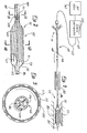
- FIG. 1 A preferred embodiment of a catheter is illustrated in Figure 1 and designated generally by the reference numeral 60.
- This catheter 60 is adapted for use in an electrosurgical catheter system which includes a radiofrequency generator 62 and a logic network 64 described in greater detail below.
- the catheter 60 includes a shaft 66 which extends along a central axis 68 between a proximal end 71 and a distal end 73. At the distal end 73, a balloon 75 is fixed to the shaft 66 of the catheter 60.
- This catheter 60 is particularly adapted for use in increasing the patency of body conduits.
- Such conduits may include the urinary track, the vascular system and particularly the coronary arteries. Whether these body conduits are defined by living tissue or by non-living deposits, they can become restricted significantly decreasing the fluid flow through the conduit. This is particularly true in the case of body conduits such as the blood vessel 77 illustrated in Figure 1.
- These vessels which are relied on to facilitate a flow of blood, are commonly blocked by plaque 80 which forms on the intimal lining of the vessel 77.
- This plaque occurs in both peripheral and coronary arteries, and typically consists of calcium, fibroblasts, and cholesterol. In all cases, the plaque 80 is undesirable as it tends to obstruct the flow of blood through the vessel 77.
- balloon catheter In a procedure commonly referred to as angioplasty, balloon catheter have been used to press this plaque against the intimal lining of the vessel 77. In this procedure which does not contemplate removal of the plaque 80, restenosis of the vessel 77 commonly
- Radiofrequency power is applied to the plaque 80 or other obstruction of the body conduit, in an electrosurgical procedure. This procedure actually reduces the volume of the plaque 80 so that the stenosis of the vessel 77 is less obstructive.
- a guide catheter 82 is inserted into the vascular system and toward the vessel 77.
- a guidewire 84 can then be introduced through the guide catheter 82 and into the vessel 77. It is of particular advantage if the guidewire 84 can be passed through the plaque 80 or other occlusion in the body conduit.
- the shaft 66 of the catheter 60 is commonly formed with a central guidewire lumen 86 extending along at least a portion of the shaft 66.
- This lumen 86 which exits the catheter 60 at the distal end 73 is threaded onto the guidewire 84 interiorly of the guide catheter 82 and exteriorly of the guidewire 84 until the balloon 75 is disposed adjacent the occlusion or plaque 80.
- the balloon 75 can be inflated and the RF generator 62 activated to remove the plaque 80 in a manner described in greater detail below.
- the balloon 75 has a wall 91 which is defined by an interior surface 93 and an exterior surface 95.
- the material of the balloon 75 is preferably nondistensible so that the wall 91 is not stretched but rather maintains a generally constant area.
- this wall 91 is collapsed and highly wrinkled in a low profile state.
- the wall 91 achieves its maximum predetermined radius in a high profile state.
- the balloon is formed from polyethylene.
- a plurality of discrete pads 100 of electrically conductive material Disposed on the exterior surface 95 of the balloon 75 are a plurality of discrete pads 100 of electrically conductive material which form a printed circuit 102. These pads 100 are formed on the exterior surface 95 preferably in a vacuum deposition process which provides the pads 100 with a minimum thickness. This greatly reduces the radial profile of the balloon 75.
- the pads 100 are not interconnected but rather are electrically separated so that they are capable of being individually or collectively energized.
- a preferred embodiment of the catheter 60 includes a plurality of the pads 100 arranged in lines extending along the length of the balloon 75 transverse to the axis 68 in a generally parallel relationship.
- a plurality of conductors 104 extend along the shaft 66 each in an electrically conductive relationship with an associated one of the pads 100. These conductors 104 extend from the pads 100 along the shaft 66 to the proximal end 71 of the catheter 60. By energizing the conductors 104, the discrete pads 100 also become energized to facilitate electrosurgical cutting at the balloon 75.
- the conductors 104 are discrete wires which run interiorly of the shaft 66 from the proximal end 71 toward the distal end 73.
- the shaft 66 is formed with not only the guidewire lumen 86 but also an inflation lumen 106, and perhaps additional lumens 108 for other purposes such as medication delivery.
- the inflation lumen 106 will typically exit the shaft 66 beneath the balloon 75 thereby permitting the balloon 75 to be inflated from the proximal end 71 of the catheter 60.
- One of the other lumens 108 or perhaps the inflation lumen 106 can be used to house the conductors 104 interiorly of the shaft 66.
- each of the conductors 104 passes exteriorly of the shaft 66 through one of the holes 111 and is soldered or otherwise electrically coupled to an associated one of the pads 100 which form the printed circuit 102 on the exterior surface 95 of the balloon 75.
- the conductors 104 are bundled in a cable 113 which is connected through the logic network 64 to the generator 62. Power from the generator 62 is selectively introduced into the conductors 104 to energize the pads 100 of the printed circuit 102.
- Vaporizing, cutting, incising, removing or other altering of the material, such as the plaque 80 is accomplished by the arcing of radiofrequency current from the electrode, such as the pad 100, to the material.
- the electrode such as the pad 100
- the coating 115 can be relied on for this function. By controlling the thickness of the coating 115 to a predetermined dimension, a gap is maintained between the tissue and the pads 100. This gap facilitates the desirable arcing which occurs through the slit 117.
- the coating 115 can be vacuum deposited over the printed circuit 102.
- FIG. 5 A further embodiment of the invention is illustrated in Figure 5.
- structural elements which are similar to those previously discussed are designated by the same reference numeral followed by the lower case letter "a”.
- this embodiment of the catheter 50a includes the shaft 66a.
- the pads 100a are relatively small in size and may have, for example, a circular configuration.
- the number and orientation of the pads is not critical to the invention. Nevertheless, it can be seen in Figure 12 that the pads 100a can be oriented in rows, such as the row 118, columns, such as the column 120, and diagonals, such as the diagonal 122.
- Each of the pads 100a is electrically connected to a lead 124 which extends to the proximal end of the balloon 75a.
- the pads 100a and leads 124 can be printed on the exterior surface 95a of the balloon 75 in a vacuum deposition process.
- the insulation layer 115a can be similarly printed over the pads 100a and the leads 124.
- the shaft 66a has a different structural configuration than that previously discussed. Nevertheless, this shaft 66a, as well as the other embodiments of the shaft 66 are interchangeable with the various balloon embodiments.
- the shaft 16a has a guidewire lumen 86a as well as an inflation lumen 106a.
- the conductors 104a are formed on an exterior surface 131 of the shaft 66a. These conductors 104a extend from the proximal end 71 distally to the balloon 75a. Vacuum deposition of these conductors 104a on the exterior surface 131 provides the necessary continuity along the shaft 66a without greatly increasing its radial dimension.
- the conductors 104a can be soldered or otherwise electrically coupled to the leads 124 present at the proximal end of the balloon 75a.
- the conductors 104a provide electrical continuity from the proximal end 71 of the catheter 60a to each of the pads 100a of the printed circuit 102a.
- a coating 133 of insulation can be applied over the exterior surface 131 of the shaft 66a in order to insulate the conductors 104a.
- the conductors 104a can be soldered to discrete wires which form the cable 113. Energizing this cable 113 and conductors 104a through the logic network 64 enables the electrosurgical cutting to take place.
- This network 64 includes for each of the conductors 104a and associated pads 100a, a switch such as that illustrated in Figure 8 and designated generally by the reference numeral 135.
- a switch such as that illustrated in Figure 8 and designated generally by the reference numeral 135.
- the switch 135 When the switch 135 is closed, the power provided by the generator 62 is passed through the associated conductor 104a to the associated pad 100a. Electrosurgical cutting occurs at this pad.
- a particular switch 135 is opened, the power presented by the generator 12 does not pass through the logic network so the associated pad 100a is not energized. Accordingly, electrosurgical cutting does not take place at this pad.
- FIG 8. A further embodiment of the catheter is illustrated in Figure 8. As in the previous embodiment, structural elements which are similar to those previously discussed are designated by the same reference numeral followed in this case by the lower case letter "b". This particular embodiment takes advantage of the fact that the wall 91b of the balloon 75b has two surfaces, the interior surface 93b and the exterior 95b. As in the previous embodiment, the pads 100b can be formed as the printed circuit 102b on the exterior surface 95b. Similarly, the conductors 104b can be formed as a second printed circuit 128 on the exterior surface 131b of the shaft 66b.
- This embodiment differs from that of Figure 5 in the provision of a plurality of holes 140 each extending through the balloon wall 91b beneath an associated one of the pads 100b. These holes permit the leads 124b to be formed on the interior surface 93b of the balloon 75b. The leads 124b extend through the holes 140 into electrical contact with the associated pad 100b.
- the embodiment of Figure 8 is configured with three printed circuits: the printed circuit 102b comprising the pads 100b, the second printed circuit 128 comprising the conductors 104b, and a third printed circuit 142 comprising the leads 124b.
- the leads 124b are formed on the interior surface 93b of the balloon 75b. This enables the leads 124b to be pressed into electrical conducting relationship with the conductors 104b on the exterior surface 131b of the shaft 66b. Increased pressure facilitating this electrical contacting relationship, can be provided by a plurality of windings 144 which radially compress the leads 124b against the conductors 104b.
- the insulation layer 115b can be formed over the pads 100b on the exterior surface 95b of the balloon wall 91b.
- This insulation layer 115b can be provided with a plurality of the slots 117b each providing access through the layer 115b to an associated one of the pads 100b.
Landscapes
- Health & Medical Sciences (AREA)
- Life Sciences & Earth Sciences (AREA)
- Surgery (AREA)
- Engineering & Computer Science (AREA)
- Heart & Thoracic Surgery (AREA)
- Animal Behavior & Ethology (AREA)
- General Health & Medical Sciences (AREA)
- Biomedical Technology (AREA)
- Veterinary Medicine (AREA)
- Public Health (AREA)
- Nuclear Medicine, Radiotherapy & Molecular Imaging (AREA)
- Medical Informatics (AREA)
- Molecular Biology (AREA)
- Vascular Medicine (AREA)
- Physics & Mathematics (AREA)
- Plasma & Fusion (AREA)
- Otolaryngology (AREA)
- Child & Adolescent Psychology (AREA)
- Biophysics (AREA)
- Pulmonology (AREA)
- Anesthesiology (AREA)
- Hematology (AREA)
- Orthopedic Medicine & Surgery (AREA)
- Cardiology (AREA)
- Media Introduction/Drainage Providing Device (AREA)
- Surgical Instruments (AREA)
Description
Claims (12)
- An angioplasty catheter system (6) for increasing the patency of a body vessel by altering an obstruction in the body vessel, comprising:characterized in that,an elongate shaft (66) extending along a central longitudinal axis (68) between a proximal end (71) and a distal end (73), the shaft having a length sufficient to extend from a percutaneous insertion site to an operative site at the location of the obstruction in the vessel;conductor means (102) disposed at the distal end of the shaft for electrical connecting with an electrosurgical generator, the conductor means being movable from a low profile position in proximity to the axis of the shaft to a high profile position in proximity to the obstruction at the operative site;means (75) operable from the proximal end of the shaft for moving a printed circuit (100) having at least one electrical conductor of said conductor means, between the low profile position and the high profile position in proximity with the obstruction;
a layer of insulation (115) covers the printed circuit and having at least one slit (117) disposed over the at least one conductor for reducing an exposure of the at least one conductor and for spacing the printed circuit from direct contact with the body vessel; and
means (104) for electrosurgically energizing the at least one conductor in the high profile position at the operative site to thereby generate an electric arc from the at least one conductor and through the slit to the body vessel such that the obstruction in proximity to the at least one conductor is altered. - The catheter system as recited in Claim 1, wherein the moving means includes:portions of the shaft defining an inflation lumen (106) extending between the proximal end of the shaft and the distal end of the shaft;a balloon (75) disposed radially inwardly of the printed circuit at the distal end of the shaft in fluid flow communication with the inflation lumen of the shaft; andmeans for introducing an inflation medium into the inflation lumen at the proximal end of the shaft for inflating the balloon to move the printed circuit between the low profile position and the high profile position.
- The catheter system as recited in Claim 2, wherein the printed circuit is disposed on the exterior surface (95) of the balloon.
- The catheter system as recited in any preceding claim, wherein the means for electrosurgically energizing the at least one conductor includes conducting means for receiving a radio frequency electrical current from an electrosurgical generator at the proximal end of the shaft and for introducing the radio frequency electrical current to the at least one conductor at the distal end of the shaft.
- The catheter system as recited in any preceding claim, wherein the printed circuit is a first printed circuit including a plurality of discrete areas of electrically conductive material and the conducting means comprises:a second printed circuit (104a) disposed on the shaft and including a plurality of discrete conductors each extending along the shaft from the proximal end of the distal end; andmeans (124) for electrically coupling each of the conductors of the second printed circuit with an associated one of the discrete areas of conductive material of the first printed circuit.
- The catheter system as claimed in Claim 5, wherein the plurality of conductors of the second printed circuit comprise vacuum deposited conductors on the exterior surface of the shaft; and wherein each of the discrete areas of electrically conductive material is electrically connected to an electrosurgical generator by a respective one of the vacuum-deposited plurality of conductors.
- The catheter system as recited in Claims 5 or 6, wherein the first printed circuit is vacuum-deposited.
- The catheter system as recited in any preceding claim, wherein the layer of insulation comprises a vacuum-deposited layer of insulation.
- The catheter system as recited in claim 5, further comprising:logic means (64) for selectively energizing the discrete areas of the first printed circuit in a predetermined pattern; wherebythe material defining the body conduit can be electrosurgically cut along different lines to increase the patency of the body conduit.
- The catheter system as recited in Claim 9, wherein the discrete areas of electrically conductive material is arranged on the balloon in at least one of rows, diagonals, and columns, and
the logic means being adapted to selectively energize the discrete areas of electrically conductive material along at least one of the rows (118), diagonals (122), and columns (120), to thereby facilitate electrosurgical cutting along at least one of the rows, diagonals, and columns. - The catheter system as recited in Claim 2, wherein the balloon is nondistensible.
- The catheter system as recited in any preceding claim, wherein each slit comprises a longitudinal slot having an axis and wherein the axes of at least two of said slits are collinear.
Applications Claiming Priority (3)
| Application Number | Priority Date | Filing Date | Title |
|---|---|---|---|
| US241007 | 1994-05-11 | ||
| US08/241,007 US5779698A (en) | 1989-01-18 | 1994-05-11 | Angioplasty catheter system and method for making same |
| PCT/US1995/006048 WO1995031142A1 (en) | 1994-05-11 | 1995-05-10 | Angioplasty catheter system and method for making |
Publications (3)
| Publication Number | Publication Date |
|---|---|
| EP0760628A1 EP0760628A1 (en) | 1997-03-12 |
| EP0760628A4 EP0760628A4 (en) | 1998-02-04 |
| EP0760628B1 true EP0760628B1 (en) | 2002-09-25 |
Family
ID=22908858
Family Applications (1)
| Application Number | Title | Priority Date | Filing Date |
|---|---|---|---|
| EP95919832A Expired - Lifetime EP0760628B1 (en) | 1994-05-11 | 1995-05-10 | Angioplasty catheter system |
Country Status (5)
| Country | Link |
|---|---|
| US (1) | US5779698A (en) |
| EP (1) | EP0760628B1 (en) |
| JP (1) | JPH10500333A (en) |
| DE (1) | DE69528366T2 (en) |
| WO (1) | WO1995031142A1 (en) |
Cited By (2)
| Publication number | Priority date | Publication date | Assignee | Title |
|---|---|---|---|---|
| CN112472206A (en) * | 2020-12-09 | 2021-03-12 | 河南科技大学第一附属医院 | Urological calculus washing device |
| EP4335480A4 (en) * | 2021-05-08 | 2025-03-19 | Shanghai Bio-Heart Biological Technology Co., Ltd. | IMPULSE BALLOON AND ASSOCIATED APPLICATION |
Families Citing this family (330)
| Publication number | Priority date | Publication date | Assignee | Title |
|---|---|---|---|---|
| US5823197A (en) * | 1994-06-24 | 1998-10-20 | Somnus Medical Technologies, Inc. | Method for internal ablation of turbinates |
| US5843077A (en) * | 1994-06-24 | 1998-12-01 | Somnus Medical Technologies, Inc. | Minimally invasive apparatus for internal ablation of turbinates with surface cooling |
| US6302875B1 (en) | 1996-10-11 | 2001-10-16 | Transvascular, Inc. | Catheters and related devices for forming passageways between blood vessels or other anatomical structures |
| US6139527A (en) * | 1996-03-05 | 2000-10-31 | Vnus Medical Technologies, Inc. | Method and apparatus for treating hemorrhoids |
| US6036687A (en) * | 1996-03-05 | 2000-03-14 | Vnus Medical Technologies, Inc. | Method and apparatus for treating venous insufficiency |
| US6152899A (en) * | 1996-03-05 | 2000-11-28 | Vnus Medical Technologies, Inc. | Expandable catheter having improved electrode design, and method for applying energy |
| US6033397A (en) * | 1996-03-05 | 2000-03-07 | Vnus Medical Technologies, Inc. | Method and apparatus for treating esophageal varices |
| WO1997032532A1 (en) | 1996-03-05 | 1997-09-12 | Vnus Medical Technologies, Inc. | Vascular catheter-based system for heating tissue |
| US7604633B2 (en) | 1996-04-12 | 2009-10-20 | Cytyc Corporation | Moisture transport system for contact electrocoagulation |
| US6813520B2 (en) | 1996-04-12 | 2004-11-02 | Novacept | Method for ablating and/or coagulating tissue using moisture transport |
| AU2191697A (en) * | 1996-05-22 | 1997-12-09 | Stuart D Edwards | Apparatus and methods for ablating turbinates |
| WO1997043971A2 (en) * | 1996-05-22 | 1997-11-27 | Somnus Medical Technologies, Inc. | Method and apparatus for ablating turbinates |
| US6464697B1 (en) * | 1998-02-19 | 2002-10-15 | Curon Medical, Inc. | Stomach and adjoining tissue regions in the esophagus |
| US6091995A (en) * | 1996-11-08 | 2000-07-18 | Surx, Inc. | Devices, methods, and systems for shrinking tissues |
| US6283988B1 (en) * | 1997-04-07 | 2001-09-04 | Broncus Technologies, Inc. | Bronchial stenter having expandable electrodes |
| US7992572B2 (en) | 1998-06-10 | 2011-08-09 | Asthmatx, Inc. | Methods of evaluating individuals having reversible obstructive pulmonary disease |
| US6634363B1 (en) | 1997-04-07 | 2003-10-21 | Broncus Technologies, Inc. | Methods of treating lungs having reversible obstructive pulmonary disease |
| US5972026A (en) | 1997-04-07 | 1999-10-26 | Broncus Technologies, Inc. | Bronchial stenter having diametrically adjustable electrodes |
| US6273907B1 (en) | 1997-04-07 | 2001-08-14 | Broncus Technologies, Inc. | Bronchial stenter |
| US6411852B1 (en) | 1997-04-07 | 2002-06-25 | Broncus Technologies, Inc. | Modification of airways by application of energy |
| US7027869B2 (en) | 1998-01-07 | 2006-04-11 | Asthmatx, Inc. | Method for treating an asthma attack |
| US7425212B1 (en) | 1998-06-10 | 2008-09-16 | Asthmatx, Inc. | Devices for modification of airways by transfer of energy |
| US6488673B1 (en) | 1997-04-07 | 2002-12-03 | Broncus Technologies, Inc. | Method of increasing gas exchange of a lung |
| US6200333B1 (en) | 1997-04-07 | 2001-03-13 | Broncus Technologies, Inc. | Bronchial stenter |
| US6083255A (en) * | 1997-04-07 | 2000-07-04 | Broncus Technologies, Inc. | Bronchial stenter |
| US6500174B1 (en) | 1997-07-08 | 2002-12-31 | Atrionix, Inc. | Circumferential ablation device assembly and methods of use and manufacture providing an ablative circumferential band along an expandable member |
| US6869431B2 (en) | 1997-07-08 | 2005-03-22 | Atrionix, Inc. | Medical device with sensor cooperating with expandable member |
| US6179832B1 (en) * | 1997-09-11 | 2001-01-30 | Vnus Medical Technologies, Inc. | Expandable catheter having two sets of electrodes |
| US6258084B1 (en) | 1997-09-11 | 2001-07-10 | Vnus Medical Technologies, Inc. | Method for applying energy to biological tissue including the use of tumescent tissue compression |
| US6401719B1 (en) | 1997-09-11 | 2002-06-11 | Vnus Medical Technologies, Inc. | Method of ligating hollow anatomical structures |
| US6200312B1 (en) * | 1997-09-11 | 2001-03-13 | Vnus Medical Technologies, Inc. | Expandable vein ligator catheter having multiple electrode leads |
| US6014589A (en) | 1997-11-12 | 2000-01-11 | Vnus Medical Technologies, Inc. | Catheter having expandable electrodes and adjustable stent |
| US7921855B2 (en) | 1998-01-07 | 2011-04-12 | Asthmatx, Inc. | Method for treating an asthma attack |
| US6231595B1 (en) | 1998-03-31 | 2001-05-15 | Innercool Therapies, Inc. | Circulating fluid hypothermia method and apparatus |
| DE19805407A1 (en) * | 1998-02-11 | 1999-08-19 | Storz Endoskop Gmbh | Device for ablating tissue on an inner surface of a body cavity |
| US6091993A (en) | 1998-02-19 | 2000-07-18 | American Medical Systems, Inc. | Methods and apparatus for an electrode balloon |
| US6602276B2 (en) * | 1998-03-31 | 2003-08-05 | Innercool Therapies, Inc. | Method and device for performing cooling- or cryo-therapies for, e.g., angioplasty with reduced restenosis or pulmonary vein cell necrosis to inhibit atrial fibrillation |
| US8551082B2 (en) | 1998-05-08 | 2013-10-08 | Cytyc Surgical Products | Radio-frequency generator for powering an ablation device |
| US6231572B1 (en) * | 1998-05-29 | 2001-05-15 | Applied Medical Resources Corporation | Electrosurgical catheter apparatus and method |
| US7198635B2 (en) | 2000-10-17 | 2007-04-03 | Asthmatx, Inc. | Modification of airways by application of energy |
| US8181656B2 (en) | 1998-06-10 | 2012-05-22 | Asthmatx, Inc. | Methods for treating airways |
| US6322559B1 (en) | 1998-07-06 | 2001-11-27 | Vnus Medical Technologies, Inc. | Electrode catheter having coil structure |
| AU5485999A (en) * | 1998-08-13 | 2000-03-06 | Keravision, Inc. | Corneal electrosurgical probe with a variable-height active site |
| US6468297B1 (en) * | 1999-02-24 | 2002-10-22 | Cryovascular Systems, Inc. | Cryogenically enhanced intravascular interventions |
| ES2287002T3 (en) * | 1999-03-02 | 2007-12-16 | Atrionix, Inc. | HEADSET ABLATION INSTRUMENT WITH BALL AND DETECTOR. |
| US7113821B1 (en) | 1999-08-25 | 2006-09-26 | Johnson & Johnson Consumer Companies, Inc. | Tissue electroperforation for enhanced drug delivery |
| US7133717B2 (en) * | 1999-08-25 | 2006-11-07 | Johnson & Johnson Consumer Companies, Inc. | Tissue electroperforation for enhanced drug delivery and diagnostic sampling |
| HK1050126A1 (en) | 1999-11-16 | 2003-06-13 | Barrx Medical, Inc. | System and method of treating abnormal tissue in the human esophagus |
| US20040215235A1 (en) | 1999-11-16 | 2004-10-28 | Barrx, Inc. | Methods and systems for determining physiologic characteristics for treatment of the esophagus |
| US20060095032A1 (en) | 1999-11-16 | 2006-05-04 | Jerome Jackson | Methods and systems for determining physiologic characteristics for treatment of the esophagus |
| US20040220559A1 (en) * | 2000-03-01 | 2004-11-04 | Kramer Hans W. | Preparation of working fluid for use in cryotherapies |
| AU2001249308A1 (en) * | 2000-03-24 | 2001-10-15 | Johns Hopkins University | Peritoneal cavity device and method |
| US8251070B2 (en) | 2000-03-27 | 2012-08-28 | Asthmatx, Inc. | Methods for treating airways |
| US7104987B2 (en) | 2000-10-17 | 2006-09-12 | Asthmatx, Inc. | Control system and process for application of energy to airway walls and other mediums |
| US7029450B2 (en) | 2001-12-14 | 2006-04-18 | Boston Scientific Scimed, Inc. | Dilation catheter assembly and related methods |
| US7620451B2 (en) | 2005-12-29 | 2009-11-17 | Ardian, Inc. | Methods and apparatus for pulsed electric field neuromodulation via an intra-to-extravascular approach |
| US20070135875A1 (en) | 2002-04-08 | 2007-06-14 | Ardian, Inc. | Methods and apparatus for thermally-induced renal neuromodulation |
| US9308044B2 (en) | 2002-04-08 | 2016-04-12 | Medtronic Ardian Luxembourg S.A.R.L. | Methods for therapeutic renal neuromodulation |
| US7853333B2 (en) | 2002-04-08 | 2010-12-14 | Ardian, Inc. | Methods and apparatus for multi-vessel renal neuromodulation |
| US20110207758A1 (en) | 2003-04-08 | 2011-08-25 | Medtronic Vascular, Inc. | Methods for Therapeutic Renal Denervation |
| US20070129761A1 (en) | 2002-04-08 | 2007-06-07 | Ardian, Inc. | Methods for treating heart arrhythmia |
| US7756583B2 (en) | 2002-04-08 | 2010-07-13 | Ardian, Inc. | Methods and apparatus for intravascularly-induced neuromodulation |
| US9308043B2 (en) | 2002-04-08 | 2016-04-12 | Medtronic Ardian Luxembourg S.A.R.L. | Methods for monopolar renal neuromodulation |
| US20080213331A1 (en) | 2002-04-08 | 2008-09-04 | Ardian, Inc. | Methods and devices for renal nerve blocking |
| US7653438B2 (en) | 2002-04-08 | 2010-01-26 | Ardian, Inc. | Methods and apparatus for renal neuromodulation |
| US8774922B2 (en) | 2002-04-08 | 2014-07-08 | Medtronic Ardian Luxembourg S.A.R.L. | Catheter apparatuses having expandable balloons for renal neuromodulation and associated systems and methods |
| US7162303B2 (en) | 2002-04-08 | 2007-01-09 | Ardian, Inc. | Renal nerve stimulation method and apparatus for treatment of patients |
| US8150519B2 (en) | 2002-04-08 | 2012-04-03 | Ardian, Inc. | Methods and apparatus for bilateral renal neuromodulation |
| US8347891B2 (en) | 2002-04-08 | 2013-01-08 | Medtronic Ardian Luxembourg S.A.R.L. | Methods and apparatus for performing a non-continuous circumferential treatment of a body lumen |
| US8145316B2 (en) | 2002-04-08 | 2012-03-27 | Ardian, Inc. | Methods and apparatus for renal neuromodulation |
| US20140018880A1 (en) | 2002-04-08 | 2014-01-16 | Medtronic Ardian Luxembourg S.A.R.L. | Methods for monopolar renal neuromodulation |
| US7617005B2 (en) | 2002-04-08 | 2009-11-10 | Ardian, Inc. | Methods and apparatus for thermally-induced renal neuromodulation |
| US9636174B2 (en) | 2002-04-08 | 2017-05-02 | Medtronic Ardian Luxembourg S.A.R.L. | Methods for therapeutic renal neuromodulation |
| US20050021070A1 (en) * | 2003-01-21 | 2005-01-27 | Angioscore, Inc. | Methods and apparatus for manipulating vascular prostheses |
| US7686824B2 (en) * | 2003-01-21 | 2010-03-30 | Angioscore, Inc. | Apparatus and methods for treating hardened vascular lesions |
| US8080026B2 (en) | 2003-01-21 | 2011-12-20 | Angioscore, Inc. | Apparatus and methods for treating hardened vascular lesions |
| DE602004021104D1 (en) * | 2003-03-10 | 2009-06-25 | Kaneka Corp | Stent |
| US20040226556A1 (en) | 2003-05-13 | 2004-11-18 | Deem Mark E. | Apparatus for treating asthma using neurotoxin |
| US6921269B2 (en) * | 2003-07-30 | 2005-07-26 | Honeywell International Inc. | Relative rotation signal transfer assembly |
| DE202004021954U1 (en) | 2003-09-12 | 2013-06-19 | Vessix Vascular, Inc. | Selectable eccentric remodeling and / or ablation of atherosclerotic material |
| US7150745B2 (en) | 2004-01-09 | 2006-12-19 | Barrx Medical, Inc. | Devices and methods for treatment of luminal tissue |
| US20080234569A1 (en) * | 2004-01-20 | 2008-09-25 | Topspin Medical (Israel) Ltd. | Mri Probe for Prostate Imaging |
| US20050177130A1 (en) * | 2004-02-10 | 2005-08-11 | Angioscore, Inc. | Balloon catheter with spiral folds |
| WO2005115545A1 (en) * | 2004-05-14 | 2005-12-08 | Omnisonics Medical Technologies, Inc. | Ultrasonic probe capable of bending with aid of a balloon |
| US8920414B2 (en) * | 2004-09-10 | 2014-12-30 | Vessix Vascular, Inc. | Tuned RF energy and electrical tissue characterization for selective treatment of target tissues |
| US9713730B2 (en) | 2004-09-10 | 2017-07-25 | Boston Scientific Scimed, Inc. | Apparatus and method for treatment of in-stent restenosis |
| US8396548B2 (en) | 2008-11-14 | 2013-03-12 | Vessix Vascular, Inc. | Selective drug delivery in a lumen |
| US20060084861A1 (en) * | 2004-10-18 | 2006-04-20 | Topspin Medical (Isreal) Ltd. | Magnet and coil configurations for MRI probes |
| US20060090194A1 (en) * | 2004-10-21 | 2006-04-27 | Smiley Ernest L | Secure network management solution for Internet/computer equipment |
| US7753907B2 (en) * | 2004-10-29 | 2010-07-13 | Boston Scientific Scimed, Inc. | Medical device systems and methods |
| WO2006052940A2 (en) | 2004-11-05 | 2006-05-18 | Asthmatx, Inc. | Medical device with procedure improvement features |
| US7949407B2 (en) | 2004-11-05 | 2011-05-24 | Asthmatx, Inc. | Energy delivery devices and methods |
| US20070093802A1 (en) | 2005-10-21 | 2007-04-26 | Danek Christopher J | Energy delivery devices and methods |
| US7731712B2 (en) | 2004-12-20 | 2010-06-08 | Cytyc Corporation | Method and system for transcervical tubal occlusion |
| DK1830915T3 (en) * | 2004-12-30 | 2009-02-16 | Cook Inc | Catheter construction with plaque cutting balloon |
| US20060178685A1 (en) * | 2004-12-30 | 2006-08-10 | Cook Incorporated | Balloon expandable plaque cutting device |
| WO2006090366A2 (en) * | 2005-02-28 | 2006-08-31 | Avraham Shekalim | Apparatus and method for removing deposits from tubular structure, particularly atheroma from blood vessels |
| US7674260B2 (en) | 2005-04-28 | 2010-03-09 | Cytyc Corporation | Emergency hemostasis device utilizing energy |
| US10076641B2 (en) | 2005-05-11 | 2018-09-18 | The Spectranetics Corporation | Methods and systems for delivering substances into luminal walls |
| US7967836B2 (en) * | 2005-06-17 | 2011-06-28 | Abbott Laboratories | Dilatation balloon having reduced rigidity |
| US20070179575A1 (en) | 2005-07-21 | 2007-08-02 | Esch Brady D | Thermal therapeutic catheter with location detection enhancement |
| US20070021803A1 (en) | 2005-07-22 | 2007-01-25 | The Foundry Inc. | Systems and methods for neuromodulation for treatment of pain and other disorders associated with nerve conduction |
| WO2007014313A2 (en) * | 2005-07-26 | 2007-02-01 | Precision Thoracic Corporation | Minimally invasive methods and apparatus |
| US7708753B2 (en) | 2005-09-27 | 2010-05-04 | Cook Incorporated | Balloon catheter with extendable dilation wire |
| US8830945B2 (en) * | 2005-10-31 | 2014-09-09 | Lg Electronics Inc. | Method for processing control information in a wireless mobile communication system |
| US7997278B2 (en) | 2005-11-23 | 2011-08-16 | Barrx Medical, Inc. | Precision ablating method |
| US8702694B2 (en) | 2005-11-23 | 2014-04-22 | Covidien Lp | Auto-aligning ablating device and method of use |
| US7959627B2 (en) | 2005-11-23 | 2011-06-14 | Barrx Medical, Inc. | Precision ablating device |
| US20070198047A1 (en) * | 2005-12-20 | 2007-08-23 | Medical Components, Inc. | Cutting balloon catheter assembly |
| US8019435B2 (en) | 2006-05-02 | 2011-09-13 | Boston Scientific Scimed, Inc. | Control of arterial smooth muscle tone |
| WO2007146215A2 (en) * | 2006-06-12 | 2007-12-21 | Pankaj Patel | Endoscopically introducible expandable cautery device |
| US9814511B2 (en) | 2006-06-28 | 2017-11-14 | Medtronic Cryocath Lp | Variable geometry cooling chamber |
| EP2465470B1 (en) | 2006-06-28 | 2015-10-28 | Medtronic Ardian Luxembourg S.à.r.l. | Systems for thermally-induced renal neuromodulation |
| US8486060B2 (en) | 2006-09-18 | 2013-07-16 | Cytyc Corporation | Power ramping during RF ablation |
| JP5559539B2 (en) * | 2006-10-18 | 2014-07-23 | べシックス・バスキュラー・インコーポレイテッド | System that induces desirable temperature effects on body tissue |
| WO2008049082A2 (en) | 2006-10-18 | 2008-04-24 | Minnow Medical, Inc. | Inducing desirable temperature effects on body tissue |
| US7931647B2 (en) | 2006-10-20 | 2011-04-26 | Asthmatx, Inc. | Method of delivering energy to a lung airway using markers |
| US7846160B2 (en) | 2006-12-21 | 2010-12-07 | Cytyc Corporation | Method and apparatus for sterilization |
| US20080228139A1 (en) * | 2007-02-06 | 2008-09-18 | Cook Incorporated | Angioplasty Balloon With Concealed Wires |
| US8323307B2 (en) * | 2007-02-13 | 2012-12-04 | Cook Medical Technologies Llc | Balloon catheter with dilating elements |
| US8496653B2 (en) | 2007-04-23 | 2013-07-30 | Boston Scientific Scimed, Inc. | Thrombus removal |
| AU2008245600B2 (en) | 2007-04-27 | 2013-07-04 | Covidien Lp | Systems and methods for treating hollow anatomical structures |
| US8641711B2 (en) * | 2007-05-04 | 2014-02-04 | Covidien Lp | Method and apparatus for gastrointestinal tract ablation for treatment of obesity |
| US20080300610A1 (en) * | 2007-05-31 | 2008-12-04 | Cook Incorporated | Device for treating hardened lesions and method of use thereof |
| US8784338B2 (en) | 2007-06-22 | 2014-07-22 | Covidien Lp | Electrical means to normalize ablational energy transmission to a luminal tissue surface of varying size |
| WO2009009443A1 (en) | 2007-07-06 | 2009-01-15 | Barrx Medical, Inc. | Method and apparatus for gastrointestinal tract ablation to achieve loss of persistent and/or recurrent excess body weight following a weight-loss operation |
| CA2692669A1 (en) | 2007-07-06 | 2009-01-15 | Barrx Medical, Inc. | Ablation in the gastrointestinal tract to achieve hemostasis and eradicate lesions with a propensity for bleeding |
| US8235983B2 (en) | 2007-07-12 | 2012-08-07 | Asthmatx, Inc. | Systems and methods for delivering energy to passageways in a patient |
| US8646460B2 (en) * | 2007-07-30 | 2014-02-11 | Covidien Lp | Cleaning device and methods |
| US8273012B2 (en) | 2007-07-30 | 2012-09-25 | Tyco Healthcare Group, Lp | Cleaning device and methods |
| US20090171283A1 (en) * | 2007-12-27 | 2009-07-02 | Cook Incorporated | Method of bonding a dilation element to a surface of an angioplasty balloon |
| US20090171284A1 (en) * | 2007-12-27 | 2009-07-02 | Cook Incorporated | Dilation system |
| US8483831B1 (en) | 2008-02-15 | 2013-07-09 | Holaira, Inc. | System and method for bronchial dilation |
| US8192675B2 (en) | 2008-03-13 | 2012-06-05 | Cook Medical Technologies Llc | Cutting balloon with connector and dilation element |
| US20090264987A1 (en) * | 2008-04-18 | 2009-10-22 | Medtronic Vascular, Inc. | Stent Graft Delivery System and Method of Use |
| EP2320821B2 (en) | 2008-05-09 | 2020-12-30 | Nuvaira, Inc. | Systems for treating a bronchial tree |
| US9770297B2 (en) | 2008-06-04 | 2017-09-26 | Covidien Lp | Energy devices and methods for treating hollow anatomical structures |
| US8939991B2 (en) | 2008-06-08 | 2015-01-27 | Hotspur Technologies, Inc. | Apparatus and methods for removing obstructive material from body lumens |
| US9101382B2 (en) * | 2009-02-18 | 2015-08-11 | Hotspur Technologies, Inc. | Apparatus and methods for treating obstructions within body lumens |
| US8945160B2 (en) | 2008-07-03 | 2015-02-03 | Hotspur Technologies, Inc. | Apparatus and methods for treating obstructions within body lumens |
| US20100010521A1 (en) * | 2008-07-10 | 2010-01-14 | Cook Incorporated | Cutting balloon with movable member |
| EP2349440B1 (en) | 2008-10-07 | 2019-08-21 | Mc10, Inc. | Catheter balloon having stretchable integrated circuitry and sensor array |
| EP2370015B1 (en) * | 2008-11-11 | 2016-12-21 | Shifamed Holdings, LLC | Low profile electrode assembly |
| US9795442B2 (en) | 2008-11-11 | 2017-10-24 | Shifamed Holdings, Llc | Ablation catheters |
| KR20110104504A (en) | 2008-11-17 | 2011-09-22 | 미노우 메디컬, 인코포레이티드 | Selective accumulation of energy according to knowledge of organizational topology |
| US20100160906A1 (en) * | 2008-12-23 | 2010-06-24 | Asthmatx, Inc. | Expandable energy delivery devices having flexible conductive elements and associated systems and methods |
| US8652129B2 (en) | 2008-12-31 | 2014-02-18 | Medtronic Ardian Luxembourg S.A.R.L. | Apparatus, systems, and methods for achieving intravascular, thermally-induced renal neuromodulation |
| US20120109057A1 (en) | 2009-02-18 | 2012-05-03 | Hotspur Technologies, Inc. | Apparatus and methods for treating obstructions within body lumens |
| US8551096B2 (en) | 2009-05-13 | 2013-10-08 | Boston Scientific Scimed, Inc. | Directional delivery of energy and bioactives |
| EP2435814B1 (en) | 2009-05-27 | 2017-09-27 | Micromass UK Limited | System and method for identification of biological tissues |
| CA2764859C (en) | 2009-06-24 | 2018-09-25 | Shifamed, Llc | Steerable medical delivery devices and methods of use |
| US8920369B2 (en) | 2009-06-24 | 2014-12-30 | Shifamed Holdings, Llc | Steerable delivery sheaths |
| US8282628B2 (en) * | 2009-10-26 | 2012-10-09 | Globus Medical, Inc. | Vertebral body nerve and vein cauterizing system and method |
| CN104856757B (en) | 2009-10-27 | 2017-06-23 | 赫莱拉公司 | Delivery apparatus with coolable energy transmitting device |
| EP4111995A1 (en) | 2009-11-11 | 2023-01-04 | Nuvaira, Inc. | Device for treating tissue and controlling stenosis |
| US8911439B2 (en) | 2009-11-11 | 2014-12-16 | Holaira, Inc. | Non-invasive and minimally invasive denervation methods and systems for performing the same |
| US8348987B2 (en) | 2009-12-22 | 2013-01-08 | Cook Medical Technologies Llc | Balloon with scoring member |
| JP2013521995A (en) | 2010-03-24 | 2013-06-13 | シファメド・ホールディングス・エルエルシー | Endovascular tissue destruction |
| AU2011238925B2 (en) | 2010-04-09 | 2016-06-16 | Vessix Vascular, Inc. | Power generating and control apparatus for the treatment of tissue |
| US9192790B2 (en) | 2010-04-14 | 2015-11-24 | Boston Scientific Scimed, Inc. | Focused ultrasonic renal denervation |
| EP2380604A1 (en) | 2010-04-19 | 2011-10-26 | InnoRa Gmbh | Improved coating formulations for scoring or cutting balloon catheters |
| US9655677B2 (en) | 2010-05-12 | 2017-05-23 | Shifamed Holdings, Llc | Ablation catheters including a balloon and electrodes |
| CA2797130A1 (en) | 2010-05-12 | 2011-11-17 | Shifamed Holdings, Llc | Low profile electrode assembly |
| US8473067B2 (en) | 2010-06-11 | 2013-06-25 | Boston Scientific Scimed, Inc. | Renal denervation and stimulation employing wireless vascular energy transfer arrangement |
| US9084609B2 (en) | 2010-07-30 | 2015-07-21 | Boston Scientific Scime, Inc. | Spiral balloon catheter for renal nerve ablation |
| US9463062B2 (en) | 2010-07-30 | 2016-10-11 | Boston Scientific Scimed, Inc. | Cooled conductive balloon RF catheter for renal nerve ablation |
| US9358365B2 (en) | 2010-07-30 | 2016-06-07 | Boston Scientific Scimed, Inc. | Precision electrode movement control for renal nerve ablation |
| US9408661B2 (en) | 2010-07-30 | 2016-08-09 | Patrick A. Haverkost | RF electrodes on multiple flexible wires for renal nerve ablation |
| US9155589B2 (en) | 2010-07-30 | 2015-10-13 | Boston Scientific Scimed, Inc. | Sequential activation RF electrode set for renal nerve ablation |
| CA2807277C (en) | 2010-08-05 | 2020-05-12 | Medtronic Af Luxembourg S.A.R.L. | Cryoablation apparatuses, systems, and methods for renal neuromodulation |
| TWI556849B (en) | 2010-10-21 | 2016-11-11 | 美敦力阿福盧森堡公司 | Catheter apparatus for renal neuromodulation |
| CN202665687U (en) | 2010-10-25 | 2013-01-16 | 美敦力Af卢森堡有限责任公司 | Catheter device used for treatment of human patient via renal denervation |
| US8974451B2 (en) | 2010-10-25 | 2015-03-10 | Boston Scientific Scimed, Inc. | Renal nerve ablation using conductive fluid jet and RF energy |
| US20120116486A1 (en) | 2010-10-25 | 2012-05-10 | Medtronic Ardian Luxembourg S.A.R.L. | Microwave catheter apparatuses, systems, and methods for renal neuromodulation |
| CN103313671B (en) | 2010-10-25 | 2017-06-06 | 美敦力Af卢森堡有限责任公司 | Apparatus, system and method for estimation and feedback of neuromodulation therapy |
| US9060755B2 (en) | 2010-10-26 | 2015-06-23 | Medtronic Ardian Luxembourg S.A.R.L. | Neuromodulation cryotherapeutic devices and associated systems and methods |
| US9220558B2 (en) | 2010-10-27 | 2015-12-29 | Boston Scientific Scimed, Inc. | RF renal denervation catheter with multiple independent electrodes |
| US9028485B2 (en) | 2010-11-15 | 2015-05-12 | Boston Scientific Scimed, Inc. | Self-expanding cooling electrode for renal nerve ablation |
| US9668811B2 (en) | 2010-11-16 | 2017-06-06 | Boston Scientific Scimed, Inc. | Minimally invasive access for renal nerve ablation |
| US9089350B2 (en) | 2010-11-16 | 2015-07-28 | Boston Scientific Scimed, Inc. | Renal denervation catheter with RF electrode and integral contrast dye injection arrangement |
| US9326751B2 (en) | 2010-11-17 | 2016-05-03 | Boston Scientific Scimed, Inc. | Catheter guidance of external energy for renal denervation |
| US10292754B2 (en) | 2010-11-17 | 2019-05-21 | Medtronic Ardian Luxembourg S.A.R.L. | Therapeutic renal neuromodulation for treating dyspnea and associated systems and methods |
| US9060761B2 (en) | 2010-11-18 | 2015-06-23 | Boston Scientific Scime, Inc. | Catheter-focused magnetic field induced renal nerve ablation |
| US9023034B2 (en) | 2010-11-22 | 2015-05-05 | Boston Scientific Scimed, Inc. | Renal ablation electrode with force-activatable conduction apparatus |
| US9192435B2 (en) | 2010-11-22 | 2015-11-24 | Boston Scientific Scimed, Inc. | Renal denervation catheter with cooled RF electrode |
| US20120157993A1 (en) | 2010-12-15 | 2012-06-21 | Jenson Mark L | Bipolar Off-Wall Electrode Device for Renal Nerve Ablation |
| JP5877162B2 (en) * | 2010-12-21 | 2016-03-02 | テルモ株式会社 | Balloon catheter and energization system |
| WO2012100095A1 (en) | 2011-01-19 | 2012-07-26 | Boston Scientific Scimed, Inc. | Guide-compatible large-electrode catheter for renal nerve ablation with reduced arterial injury |
| US9089312B2 (en) * | 2011-03-10 | 2015-07-28 | Western New England University | Tamponade for biopsy surgery and method of operation |
| US10278774B2 (en) | 2011-03-18 | 2019-05-07 | Covidien Lp | Selectively expandable operative element support structure and methods of use |
| US20120259269A1 (en) | 2011-04-08 | 2012-10-11 | Tyco Healthcare Group Lp | Iontophoresis drug delivery system and method for denervation of the renal sympathetic nerve and iontophoretic drug delivery |
| CN103930061B (en) | 2011-04-25 | 2016-09-14 | 美敦力阿迪安卢森堡有限责任公司 | Relevant low temperature sacculus for restricted conduit wall cryogenic ablation limits the device and method disposed |
| GB2492064B (en) * | 2011-06-15 | 2016-06-01 | Gyrus Medical Ltd | Electrosurgical instrument |
| AU2012283908B2 (en) | 2011-07-20 | 2017-02-16 | Boston Scientific Scimed, Inc. | Percutaneous devices and methods to visualize, target and ablate nerves |
| WO2013016203A1 (en) | 2011-07-22 | 2013-01-31 | Boston Scientific Scimed, Inc. | Nerve modulation system with a nerve modulation element positionable in a helical guide |
| WO2013022853A1 (en) * | 2011-08-05 | 2013-02-14 | Mc10, Inc. | Catheter balloon methods and apparatus employing sensing elements |
| CN104125815B (en) * | 2011-10-04 | 2018-08-03 | 维西克斯血管公司 | Device and method for treating in-stent restenosis |
| EP2765942B1 (en) | 2011-10-10 | 2016-02-24 | Boston Scientific Scimed, Inc. | Medical devices including ablation electrodes |
| EP2765940B1 (en) | 2011-10-11 | 2015-08-26 | Boston Scientific Scimed, Inc. | Off-wall electrode device for nerve modulation |
| US9420955B2 (en) | 2011-10-11 | 2016-08-23 | Boston Scientific Scimed, Inc. | Intravascular temperature monitoring system and method |
| US9364284B2 (en) | 2011-10-12 | 2016-06-14 | Boston Scientific Scimed, Inc. | Method of making an off-wall spacer cage |
| US9162046B2 (en) | 2011-10-18 | 2015-10-20 | Boston Scientific Scimed, Inc. | Deflectable medical devices |
| WO2013059202A1 (en) | 2011-10-18 | 2013-04-25 | Boston Scientific Scimed, Inc. | Integrated crossing balloon catheter |
| ES2767093T3 (en) | 2011-11-07 | 2020-06-16 | Medtronic Ardian Luxembourg | Endovascular nerve monitoring devices and associated systems |
| CN108095821B (en) | 2011-11-08 | 2021-05-25 | 波士顿科学西美德公司 | Foraminal renal nerve ablation |
| US9119600B2 (en) | 2011-11-15 | 2015-09-01 | Boston Scientific Scimed, Inc. | Device and methods for renal nerve modulation monitoring |
| US9119632B2 (en) | 2011-11-21 | 2015-09-01 | Boston Scientific Scimed, Inc. | Deflectable renal nerve ablation catheter |
| US9192766B2 (en) | 2011-12-02 | 2015-11-24 | Medtronic Ardian Luxembourg S.A.R.L. | Renal neuromodulation methods and devices for treatment of polycystic kidney disease |
| US9265969B2 (en) | 2011-12-21 | 2016-02-23 | Cardiac Pacemakers, Inc. | Methods for modulating cell function |
| JP6158830B2 (en) | 2011-12-23 | 2017-07-05 | べシックス・バスキュラー・インコーポレイテッド | System, method and apparatus for remodeling tissue in or adjacent to a body passage |
| WO2013101446A1 (en) * | 2011-12-28 | 2013-07-04 | Boston Scientific Scimed, Inc. | Balloon expandable multi-electrode rf ablation catheter |
| US9433760B2 (en) | 2011-12-28 | 2016-09-06 | Boston Scientific Scimed, Inc. | Device and methods for nerve modulation using a novel ablation catheter with polymeric ablative elements |
| US9050106B2 (en) | 2011-12-29 | 2015-06-09 | Boston Scientific Scimed, Inc. | Off-wall electrode device and methods for nerve modulation |
| AU2013230883A1 (en) | 2012-03-07 | 2014-09-11 | Medtronic Af Luxembourg S.A.R.L. | Selective modulation of renal nerves |
| WO2013134479A1 (en) | 2012-03-08 | 2013-09-12 | Medtronic Ardian Luxembourg Sarl | Neuromodulation and associated systems and methods for the management of pain |
| AU2013230906A1 (en) | 2012-03-08 | 2014-09-18 | Medtronic Af Luxembourg S.A.R.L. | Neuromodulation and associated systems and methods for the treatment of sexual dysfunction |
| US11013549B2 (en) | 2012-03-08 | 2021-05-25 | Medtronic Ardian Luxembourg S.A.R.L. | Gastrointestinal neuromodulation and associated systems and methods |
| US9750568B2 (en) | 2012-03-08 | 2017-09-05 | Medtronic Ardian Luxembourg S.A.R.L. | Ovarian neuromodulation and associated systems and methods |
| EP3348220B1 (en) | 2012-03-08 | 2024-10-23 | Medtronic Ardian Luxembourg S.à.r.l. | Biomarker sampling in the context of neuromodulation devices and associated systems |
| AU2013230886B2 (en) | 2012-03-08 | 2015-10-01 | Medtronic Af Luxembourg S.A.R.L. | Renal neuromodulation methods and systems for treatment of hyperaldosteronism |
| US8961550B2 (en) | 2012-04-17 | 2015-02-24 | Indian Wells Medical, Inc. | Steerable endoluminal punch |
| WO2013162721A1 (en) | 2012-04-27 | 2013-10-31 | Medtronic Ardian Luxembourg Sarl | Methods and devices for localized inhibition of inflammation by ablation |
| US10258791B2 (en) | 2012-04-27 | 2019-04-16 | Medtronic Ardian Luxembourg S.A.R.L. | Catheter assemblies for neuromodulation proximate a bifurcation of a renal artery and associated systems and methods |
| EP2840991B1 (en) | 2012-04-27 | 2019-05-15 | Medtronic Ardian Luxembourg S.à.r.l. | Cryotherapeutic devices for renal neuromodulation |
| US9848950B2 (en) | 2012-04-27 | 2017-12-26 | Medtronic Ardian Luxembourg S.A.R.L. | Methods and devices for localized disease treatment by ablation |
| US9241752B2 (en) | 2012-04-27 | 2016-01-26 | Medtronic Ardian Luxembourg S.A.R.L. | Shafts with pressure relief in cryotherapeutic catheters and associated devices, systems, and methods |
| WO2013169927A1 (en) | 2012-05-08 | 2013-11-14 | Boston Scientific Scimed, Inc. | Renal nerve modulation devices |
| KR20150018801A (en) | 2012-05-11 | 2015-02-24 | 메드트로닉 아르디언 룩셈부르크 에스에이알엘 | Multi-electrode catheter assemblies for renal neuromodulation and associated systems and methods |
| EP3868321B1 (en) | 2012-06-04 | 2022-11-16 | Boston Scientific Scimed, Inc. | Systems for treating tissue of a passageway within a body |
| US9592086B2 (en) | 2012-07-24 | 2017-03-14 | Boston Scientific Scimed, Inc. | Electrodes for tissue treatment |
| WO2014032016A1 (en) | 2012-08-24 | 2014-02-27 | Boston Scientific Scimed, Inc. | Intravascular catheter with a balloon comprising separate microporous regions |
| WO2014043687A2 (en) | 2012-09-17 | 2014-03-20 | Boston Scientific Scimed, Inc. | Self-positioning electrode system and method for renal nerve modulation |
| WO2014047454A2 (en) | 2012-09-21 | 2014-03-27 | Boston Scientific Scimed, Inc. | Self-cooling ultrasound ablation catheter |
| US10398464B2 (en) | 2012-09-21 | 2019-09-03 | Boston Scientific Scimed, Inc. | System for nerve modulation and innocuous thermal gradient nerve block |
| WO2014059165A2 (en) | 2012-10-10 | 2014-04-17 | Boston Scientific Scimed, Inc. | Renal nerve modulation devices and methods |
| US20140110296A1 (en) | 2012-10-19 | 2014-04-24 | Medtronic Ardian Luxembourg S.A.R.L. | Packaging for Catheter Treatment Devices and Associated Devices, Systems, and Methods |
| US9044575B2 (en) | 2012-10-22 | 2015-06-02 | Medtronic Adrian Luxembourg S.a.r.l. | Catheters with enhanced flexibility and associated devices, systems, and methods |
| ES2733273T3 (en) | 2012-10-22 | 2019-11-28 | Medtronic Ardian Luxembourg | Catheters with improved flexibility |
| US9272132B2 (en) | 2012-11-02 | 2016-03-01 | Boston Scientific Scimed, Inc. | Medical device for treating airways and related methods of use |
| US9283374B2 (en) | 2012-11-05 | 2016-03-15 | Boston Scientific Scimed, Inc. | Devices and methods for delivering energy to body lumens |
| US9398933B2 (en) | 2012-12-27 | 2016-07-26 | Holaira, Inc. | Methods for improving drug efficacy including a combination of drug administration and nerve modulation |
| CN103932676A (en) * | 2013-01-23 | 2014-07-23 | 四川锦江电子科技有限公司 | Flexible circuit electrode |
| WO2014143571A1 (en) | 2013-03-11 | 2014-09-18 | Boston Scientific Scimed, Inc. | Medical devices for modulating nerves |
| WO2014163987A1 (en) | 2013-03-11 | 2014-10-09 | Boston Scientific Scimed, Inc. | Medical devices for modulating nerves |
| US9808311B2 (en) | 2013-03-13 | 2017-11-07 | Boston Scientific Scimed, Inc. | Deflectable medical devices |
| EP2967726A1 (en) * | 2013-03-13 | 2016-01-20 | Boston Scientific Scimed, Inc. | Steerable ablation device with linear ionically conductive balloon |
| EP2967725B1 (en) | 2013-03-15 | 2019-12-11 | Boston Scientific Scimed, Inc. | Control unit for detecting electrical leakage between electrode pads and system comprising such a control unit |
| EP2967734B1 (en) | 2013-03-15 | 2019-05-15 | Boston Scientific Scimed, Inc. | Methods and apparatuses for remodeling tissue of or adjacent to a body passage |
| EP3932470B1 (en) | 2013-03-15 | 2023-07-12 | Medtronic Ardian Luxembourg S.à.r.l. | Controlled neuromodulation systems |
| US9179974B2 (en) | 2013-03-15 | 2015-11-10 | Medtronic Ardian Luxembourg S.A.R.L. | Helical push wire electrode |
| US10265122B2 (en) | 2013-03-15 | 2019-04-23 | Boston Scientific Scimed, Inc. | Nerve ablation devices and related methods of use |
| US9066726B2 (en) | 2013-03-15 | 2015-06-30 | Medtronic Ardian Luxembourg S.A.R.L. | Multi-electrode apposition judgment using pressure elements |
| US10098694B2 (en) | 2013-04-08 | 2018-10-16 | Apama Medical, Inc. | Tissue ablation and monitoring thereof |
| US10349824B2 (en) | 2013-04-08 | 2019-07-16 | Apama Medical, Inc. | Tissue mapping and visualization systems |
| CN110141177B (en) | 2013-04-08 | 2021-11-23 | 阿帕玛医疗公司 | Ablation catheter |
| WO2014189794A1 (en) | 2013-05-18 | 2014-11-27 | Medtronic Ardian Luxembourg S.A.R.L. | Neuromodulation catheters with shafts for enhanced flexibility and control and associated devices, systems, and methods |
| US9814618B2 (en) | 2013-06-06 | 2017-11-14 | Boston Scientific Scimed, Inc. | Devices for delivering energy and related methods of use |
| US20140378968A1 (en) * | 2013-06-21 | 2014-12-25 | Boston Scientific Scimed, Inc. | Medical devices for renal nerve ablation |
| US9943365B2 (en) | 2013-06-21 | 2018-04-17 | Boston Scientific Scimed, Inc. | Renal denervation balloon catheter with ride along electrode support |
| US10022182B2 (en) | 2013-06-21 | 2018-07-17 | Boston Scientific Scimed, Inc. | Medical devices for renal nerve ablation having rotatable shafts |
| US9707036B2 (en) | 2013-06-25 | 2017-07-18 | Boston Scientific Scimed, Inc. | Devices and methods for nerve modulation using localized indifferent electrodes |
| WO2015002787A1 (en) | 2013-07-01 | 2015-01-08 | Boston Scientific Scimed, Inc. | Medical devices for renal nerve ablation |
| US10413357B2 (en) | 2013-07-11 | 2019-09-17 | Boston Scientific Scimed, Inc. | Medical device with stretchable electrode assemblies |
| WO2015006480A1 (en) | 2013-07-11 | 2015-01-15 | Boston Scientific Scimed, Inc. | Devices and methods for nerve modulation |
| CN105682594B (en) | 2013-07-19 | 2018-06-22 | 波士顿科学国际有限公司 | Helical bipolar electrodes renal denervation dominates air bag |
| JP6122217B2 (en) * | 2013-07-22 | 2017-04-26 | ボストン サイエンティフィック サイムド,インコーポレイテッドBoston Scientific Scimed,Inc. | Renal nerve ablation medical device |
| CN105555220B (en) | 2013-07-22 | 2019-05-17 | 波士顿科学国际有限公司 | Medical Devices for Renal Nerve Ablation |
| JP6479005B2 (en) | 2013-08-09 | 2019-03-06 | ボストン サイエンティフィック サイムド,インコーポレイテッドBoston Scientific Scimed,Inc. | Medical instruments |
| EP4049605A1 (en) | 2013-08-22 | 2022-08-31 | Boston Scientific Scimed Inc. | Flexible circuit having improved adhesion to a renal nerve modulation balloon |
| US9326816B2 (en) | 2013-08-30 | 2016-05-03 | Medtronic Ardian Luxembourg S.A.R.L. | Neuromodulation systems having nerve monitoring assemblies and associated devices, systems, and methods |
| US9339332B2 (en) | 2013-08-30 | 2016-05-17 | Medtronic Ardian Luxembourg S.A.R.L. | Neuromodulation catheters with nerve monitoring features for transmitting digital neural signals and associated systems and methods |
| CN105555218B (en) | 2013-09-04 | 2019-01-15 | 波士顿科学国际有限公司 | With radio frequency (RF) foley's tube rinsed with cooling capacity |
| US20150073515A1 (en) | 2013-09-09 | 2015-03-12 | Medtronic Ardian Luxembourg S.a.r.I. | Neuromodulation Catheter Devices and Systems Having Energy Delivering Thermocouple Assemblies and Associated Methods |
| CN105530885B (en) * | 2013-09-13 | 2020-09-22 | 波士顿科学国际有限公司 | Ablation balloon with vapor deposited covering |
| US9687166B2 (en) | 2013-10-14 | 2017-06-27 | Boston Scientific Scimed, Inc. | High resolution cardiac mapping electrode array catheter |
| US11246654B2 (en) | 2013-10-14 | 2022-02-15 | Boston Scientific Scimed, Inc. | Flexible renal nerve ablation devices and related methods of use and manufacture |
| US9770606B2 (en) | 2013-10-15 | 2017-09-26 | Boston Scientific Scimed, Inc. | Ultrasound ablation catheter with cooling infusion and centering basket |
| EP3057520A1 (en) | 2013-10-15 | 2016-08-24 | Boston Scientific Scimed, Inc. | Medical device balloon |
| JP6259099B2 (en) * | 2013-10-18 | 2018-01-10 | ボストン サイエンティフィック サイムド,インコーポレイテッドBoston Scientific Scimed,Inc. | Balloon catheter comprising a conductive wire with flexibility, and related uses and manufacturing methods |
| US10433902B2 (en) | 2013-10-23 | 2019-10-08 | Medtronic Ardian Luxembourg S.A.R.L. | Current control methods and systems |
| WO2015061457A1 (en) | 2013-10-25 | 2015-04-30 | Boston Scientific Scimed, Inc. | Embedded thermocouple in denervation flex circuit |
| US10286190B2 (en) | 2013-12-11 | 2019-05-14 | Cook Medical Technologies Llc | Balloon catheter with dynamic vessel engaging member |
| US11202671B2 (en) | 2014-01-06 | 2021-12-21 | Boston Scientific Scimed, Inc. | Tear resistant flex circuit assembly |
| US9956384B2 (en) | 2014-01-24 | 2018-05-01 | Cook Medical Technologies Llc | Articulating balloon catheter and method for using the same |
| EP4059563B1 (en) | 2014-01-27 | 2023-09-27 | Medtronic Ireland Manufacturing Unlimited Company | Neuromodulation catheters having jacketed neuromodulation elements and related devices |
| US9724121B2 (en) | 2014-02-02 | 2017-08-08 | TriReme Medical, LLC | Apparatus and methods for recannalization, valve repair and replacement |
| JP6325121B2 (en) | 2014-02-04 | 2018-05-16 | ボストン サイエンティフィック サイムド,インコーポレイテッドBoston Scientific Scimed,Inc. | Alternative placement of temperature sensors on bipolar electrodes |
| US11000679B2 (en) | 2014-02-04 | 2021-05-11 | Boston Scientific Scimed, Inc. | Balloon protection and rewrapping devices and related methods of use |
| US10492842B2 (en) | 2014-03-07 | 2019-12-03 | Medtronic Ardian Luxembourg S.A.R.L. | Monitoring and controlling internally administered cryotherapy |
| US10463424B2 (en) | 2014-03-11 | 2019-11-05 | Medtronic Ardian Luxembourg S.A.R.L. | Catheters with independent radial-expansion members and associated devices, systems, and methods |
| US9579149B2 (en) | 2014-03-13 | 2017-02-28 | Medtronic Ardian Luxembourg S.A.R.L. | Low profile catheter assemblies and associated systems and methods |
| EP4371512A3 (en) | 2014-04-24 | 2024-08-14 | Medtronic Ardian Luxembourg S.à.r.l. | Neuromodulation catheters having braided shafts and associated systems and methods |
| US10610292B2 (en) | 2014-04-25 | 2020-04-07 | Medtronic Ardian Luxembourg S.A.R.L. | Devices, systems, and methods for monitoring and/or controlling deployment of a neuromodulation element within a body lumen and related technology |
| US10709490B2 (en) | 2014-05-07 | 2020-07-14 | Medtronic Ardian Luxembourg S.A.R.L. | Catheter assemblies comprising a direct heating element for renal neuromodulation and associated systems and methods |
| WO2015187385A1 (en) * | 2014-06-04 | 2015-12-10 | Boston Scientific Scimed, Inc. | Pressure sensing guidewire systems with reduced pressure offsets |
| WO2016033543A1 (en) | 2014-08-28 | 2016-03-03 | Medtronic Ardian Luxembourg S.A.R.L. | Methods for assessing efficacy of renal neuromodulation and associated systems and devices |
| EP3791817B1 (en) | 2014-10-01 | 2024-05-22 | Medtronic Ardian Luxembourg S.à.r.l. | Systems for evaluating neuromodulation therapy via hemodynamic responses |
| WO2016075536A2 (en) | 2014-11-14 | 2016-05-19 | Medtronic Ardian Luxembourg S.A.R.L. | Catheter apparatuses for modulation of nerves in communication with the pulmonary system and associated systems and methods |
| US10667736B2 (en) | 2014-12-17 | 2020-06-02 | Medtronic Ardian Luxembourg S.A.R.L. | Systems and methods for assessing sympathetic nervous system tone for neuromodulation therapy |
| JP6797131B2 (en) | 2015-03-27 | 2020-12-09 | カリラ メディカル インコーポレイテッド | Manipulable medical devices, systems and usage |
| WO2016172706A1 (en) | 2015-04-24 | 2016-10-27 | Shifamed Holdings, Llc | Steerable medical devices, systems, and methods of use |
| US10561438B2 (en) | 2015-10-30 | 2020-02-18 | C.R. Bard, Inc. | Scoring balloon with translating scoring wires |
| EP3373794B1 (en) | 2015-11-09 | 2022-01-05 | Kalila Medical, Inc. | Steering assemblies for medical devices |
| CN108348146A (en) | 2015-11-16 | 2018-07-31 | 阿帕玛医疗公司 | Energy transmission device |
| US10736692B2 (en) | 2016-04-28 | 2020-08-11 | Medtronic Ardian Luxembourg S.A.R.L. | Neuromodulation and associated systems and methods for the treatment of cancer |
| US10231784B2 (en) | 2016-10-28 | 2019-03-19 | Medtronic Ardian Luxembourg S.A.R.L. | Methods and systems for optimizing perivascular neuromodulation therapy using computational fluid dynamics |
| US10531890B2 (en) * | 2016-12-30 | 2020-01-14 | C.R. Bard, Inc. | Scoring balloon with translating scoring wires |
| JP7207739B2 (en) | 2017-02-02 | 2023-01-18 | プレシジョン ソラシック, エルエルシー | Minimally Invasive Methods and Devices for Targeted Tissue Ablation |
| US10646713B2 (en) | 2017-02-22 | 2020-05-12 | Medtronic Ardian Luxembourg S.A.R.L. | Systems, devices, and associated methods for treating patients via renal neuromodulation to reduce a risk of developing cognitive impairment |
| WO2018226752A1 (en) * | 2017-06-05 | 2018-12-13 | St. Jude Medical, Cardiology Division, Inc. | Pulmonary antrum radial-linear ablation devices |
| CN116327157B (en) | 2017-08-03 | 2025-09-30 | 波士顿科学国际有限公司 | Methods for assessing fractional flow reserve |
| US11071557B2 (en) | 2017-10-19 | 2021-07-27 | Medtronic Vascular, Inc. | Catheter for creating pulse wave within vasculature |
| US12082917B2 (en) | 2018-01-24 | 2024-09-10 | Medtronic Ireland Manufacturing Unlimited Company | Systems, devices, and methods for assessing efficacy of renal neuromodulation therapy |
| EP4070720B1 (en) | 2018-02-23 | 2023-11-08 | Boston Scientific Scimed, Inc. | Methods for assessing a vessel with sequential physiological measurements |
| US11850073B2 (en) | 2018-03-23 | 2023-12-26 | Boston Scientific Scimed, Inc. | Medical device with pressure sensor |
| CN112292074B (en) | 2018-04-06 | 2024-05-10 | 波士顿科学国际有限公司 | Medical device with pressure sensor |
| CN119564167A (en) | 2018-04-18 | 2025-03-07 | 波士顿科学国际有限公司 | System for vascular assessment using continuous physiological measurements |
| US20200038089A1 (en) | 2018-07-31 | 2020-02-06 | Ethicon, Inc. | Tissue resection apparatus |
| JP6894582B2 (en) * | 2018-08-15 | 2021-06-30 | 日本ライフライン株式会社 | Balloon type electrode catheter |
| US11266817B2 (en) | 2018-10-25 | 2022-03-08 | Medtronic Vascular, Inc. | Cavitation catheter |
| EP3760242A1 (en) * | 2019-07-02 | 2021-01-06 | Biotronik Ag | Functionalized balloon surface |
| US12605150B2 (en) | 2019-07-16 | 2026-04-21 | Prana Thoracic, Inc. | Systems, devices, and methods for coring tissue |
| US12042216B2 (en) * | 2019-12-09 | 2024-07-23 | Biosense Webster (Israel) Ltd. | Irreversible-electroporation (IRE) balloon catheter with membrane-insulated high-voltage balloon wires |
| JP7384927B2 (en) * | 2019-12-24 | 2023-11-21 | 日本ライフライン株式会社 | Balloon electrode catheter |
| US12622745B2 (en) | 2020-04-30 | 2026-05-12 | Prana Thoracic, Inc. | Systems and methods for sealing cored or punctured tissue using inflatable balloon |
| US12521168B2 (en) | 2020-06-08 | 2026-01-13 | Prana Thoracic, Inc. | Tissue resection control systems and methods |
| US20220087739A1 (en) * | 2020-09-18 | 2022-03-24 | Acclarent, Inc. | Ent instrument with expandable ablation feature |
| WO2022070139A1 (en) * | 2020-09-30 | 2022-04-07 | Novocure Gmbh | Implantable arrays for providing tumor treating fields |
| US12087000B2 (en) | 2021-03-05 | 2024-09-10 | Boston Scientific Scimed, Inc. | Systems and methods for vascular image co-registration |
| CN115844487A (en) * | 2022-11-22 | 2023-03-28 | 上海精诚医疗器械有限公司 | Shock wave balloon catheter and shock wave device |
Family Cites Families (36)
| Publication number | Priority date | Publication date | Assignee | Title |
|---|---|---|---|---|
| US522254A (en) | 1894-07-03 | Machine for flanging or hemming edges of tin plates | ||
| DE2160466A1 (en) * | 1970-12-05 | 1972-06-22 | Olympus Optical Co. Ltd., Tokio | Excision forceps |
| JPS5727445Y2 (en) * | 1973-06-20 | 1982-06-15 | ||
| SU599802A1 (en) * | 1976-11-09 | 1978-03-30 | Харьковский научно-исследовательский институт общей и неотложной хирургии | Device for slitting vessel walls |
| JPS5552748A (en) * | 1978-10-12 | 1980-04-17 | Olympus Optical Co | Highhfrequency incising tool |
| JPS5917290Y2 (en) * | 1979-06-04 | 1984-05-21 | オリンパス光学工業株式会社 | High frequency knife for endoscope |
| US4273128A (en) * | 1980-01-14 | 1981-06-16 | Lary Banning G | Coronary cutting and dilating instrument |
| US4326530A (en) * | 1980-03-05 | 1982-04-27 | Fleury Jr George J | Surgical snare |
| SU938977A1 (en) * | 1980-03-12 | 1982-06-30 | Предприятие П/Я А-3903 | Device for dissection of vessels walls |
| IT8123634U1 (en) * | 1981-11-26 | 1983-05-26 | Bravo Genesio | IMPROVED HOMOGENIZING DEVICE, ESPECIALLY FOR THE PRODUCTION OF WHIPPED CREAM. |
| US4747405A (en) * | 1984-03-01 | 1988-05-31 | Vaser, Inc. | Angioplasty catheter |
| US4649924A (en) * | 1984-08-14 | 1987-03-17 | Consiglio Nazionale Delle Ricerche | Method for the detection of intracardiac electrical potential fields |
| US5226430A (en) * | 1984-10-24 | 1993-07-13 | The Beth Israel Hospital | Method for angioplasty |
| US4799479A (en) * | 1984-10-24 | 1989-01-24 | The Beth Israel Hospital Association | Method and apparatus for angioplasty |
| DE3516830A1 (en) * | 1985-05-10 | 1986-11-13 | Max Dr. 8520 Erlangen Hubmann | CATHETER |
| US4660560A (en) * | 1985-05-30 | 1987-04-28 | The Beth Israel Hospital Association | Method for treating obstructive prostatism |
| DE3519626A1 (en) * | 1985-05-31 | 1986-12-04 | Stöckert Instrumente GmbH, 8000 München | BALLOON CATHETER |
| US4669469A (en) * | 1986-02-28 | 1987-06-02 | Devices For Vascular Intervention | Single lumen atherectomy catheter device |
| US4709698A (en) * | 1986-05-14 | 1987-12-01 | Thomas J. Fogarty | Heatable dilation catheter |
| US4793348A (en) * | 1986-11-15 | 1988-12-27 | Palmaz Julio C | Balloon expandable vena cava filter to prevent migration of lower extremity venous clots into the pulmonary circulation |
| US5053044A (en) * | 1988-01-11 | 1991-10-01 | Devices For Vascular Intervention, Inc. | Catheter and method for making intravascular incisions |
| US4952357A (en) * | 1988-08-08 | 1990-08-28 | Scimed Life Systems, Inc. | Method of making a polyimide balloon catheter |
| US4919133A (en) * | 1988-08-18 | 1990-04-24 | Chiang Tien Hon | Catheter apparatus employing shape memory alloy structures |
| US5151100A (en) * | 1988-10-28 | 1992-09-29 | Boston Scientific Corporation | Heating catheters |
| AU5098290A (en) | 1989-01-18 | 1990-08-13 | Applied Urology, Inc. | Dilatation catheter assembly with cutting element |
| US4976711A (en) * | 1989-04-13 | 1990-12-11 | Everest Medical Corporation | Ablation catheter with selectively deployable electrodes |
| US5006119A (en) * | 1989-05-25 | 1991-04-09 | Engineering & Research Associates, Inc. | Hollow core coaxial catheter |
| US5045056A (en) * | 1989-09-15 | 1991-09-03 | Behl Robert S | Method and device for thermal ablation of hollow body organs |
| US5080660A (en) * | 1990-05-11 | 1992-01-14 | Applied Urology, Inc. | Electrosurgical electrode |
| JP3466183B2 (en) | 1990-05-11 | 2003-11-10 | アプライド メディカル リソーセス コーポレイション | Dilatation catheter assembly with cutting element |
| US5196024A (en) * | 1990-07-03 | 1993-03-23 | Cedars-Sinai Medical Center | Balloon catheter with cutting edge |
| US5195965A (en) * | 1991-03-07 | 1993-03-23 | Shantha Totada R | Method and apparatus for localized treatment of human viral infections and cancers |
| US5492529A (en) * | 1991-12-18 | 1996-02-20 | Gynelab Products | Tissue necrosing apparatus and method for using same including treatment of benign prostrate hypertrophy |
| US5277201A (en) * | 1992-05-01 | 1994-01-11 | Vesta Medical, Inc. | Endometrial ablation apparatus and method |
| US5443470A (en) * | 1992-05-01 | 1995-08-22 | Vesta Medical, Inc. | Method and apparatus for endometrial ablation |
| US5476495A (en) * | 1993-03-16 | 1995-12-19 | Ep Technologies, Inc. | Cardiac mapping and ablation systems |
-
1994
- 1994-05-11 US US08/241,007 patent/US5779698A/en not_active Expired - Fee Related
-
1995
- 1995-05-10 WO PCT/US1995/006048 patent/WO1995031142A1/en not_active Ceased
- 1995-05-10 DE DE69528366T patent/DE69528366T2/en not_active Expired - Fee Related
- 1995-05-10 EP EP95919832A patent/EP0760628B1/en not_active Expired - Lifetime
- 1995-05-10 JP JP7529827A patent/JPH10500333A/en active Pending
Cited By (3)
| Publication number | Priority date | Publication date | Assignee | Title |
|---|---|---|---|---|
| CN112472206A (en) * | 2020-12-09 | 2021-03-12 | 河南科技大学第一附属医院 | Urological calculus washing device |
| CN112472206B (en) * | 2020-12-09 | 2022-02-11 | 河南科技大学第一附属医院 | Urological calculus washing device |
| EP4335480A4 (en) * | 2021-05-08 | 2025-03-19 | Shanghai Bio-Heart Biological Technology Co., Ltd. | IMPULSE BALLOON AND ASSOCIATED APPLICATION |
Also Published As
| Publication number | Publication date |
|---|---|
| DE69528366D1 (en) | 2002-10-31 |
| US5779698A (en) | 1998-07-14 |
| DE69528366T2 (en) | 2003-01-23 |
| EP0760628A4 (en) | 1998-02-04 |
| EP0760628A1 (en) | 1997-03-12 |
| JPH10500333A (en) | 1998-01-13 |
| WO1995031142A1 (en) | 1995-11-23 |
Similar Documents
| Publication | Publication Date | Title |
|---|---|---|
| US5779698A (en) | Angioplasty catheter system and method for making same | |
| EP0527848B1 (en) | Electrosurgical electrode | |
| US6562031B2 (en) | Guide wire system for RF recanalization of vascular blockages | |
| US5904679A (en) | Catheter with electrosurgical cutter | |
| CA2082621C (en) | Dilatation catheter assembly with cutting element | |
| US6582423B1 (en) | Electrosurgical systems and methods for recanalization of occluded body lumens | |
| US6585732B2 (en) | Fluid-assisted electrosurgical device | |
| US6855143B2 (en) | Electrosurgical systems and methods for recanalization of occluded body lumens | |
| US4976711A (en) | Ablation catheter with selectively deployable electrodes | |
| US5078717A (en) | Ablation catheter with selectively deployable electrodes | |
| EP1105060B1 (en) | Electrocatheter for inducing vessel stenosys having two arrays of diverging electrodes | |
| US6063085A (en) | Apparatus and method for sealing vascular punctures | |
| EP1559377B1 (en) | Bipolar electrosurgical snare | |
| US5057107A (en) | Ablation catheter with selectively deployable electrodes | |
| US5810810A (en) | Apparatus and method for sealing vascular punctures | |
| US5628746A (en) | Dilatation catheter assembly with cutting element and method of using the same | |
| US6689126B1 (en) | Expandable vein ligator catheter and method of use | |
| US5713942A (en) | Body cavity ablation apparatus and model | |
| WO1997032525A1 (en) | Apparatus for creating linear lesions by ablation | |
| EP2026707A2 (en) | Dilatation catheter assembly with bipolar cutting element | |
| WO1994024948A1 (en) | Apparatus and method for sealing vascular punctures | |
| EP0569548B1 (en) | Catheter with electrosurgical cutter | |
| CA2161099C (en) | Apparatus and method for sealing vascular punctures |
Legal Events
| Date | Code | Title | Description |
|---|---|---|---|
| PUAI | Public reference made under article 153(3) epc to a published international application that has entered the european phase |
Free format text: ORIGINAL CODE: 0009012 |
|
| 17P | Request for examination filed |
Effective date: 19961108 |
|
| AK | Designated contracting states |
Kind code of ref document: A1 Designated state(s): DE FR |
|
| A4 | Supplementary search report drawn up and despatched |
Effective date: 19971217 |
|
| AK | Designated contracting states |
Kind code of ref document: A4 Designated state(s): DE FR |
|
| 17Q | First examination report despatched |
Effective date: 19981125 |
|
| RAP1 | Party data changed (applicant data changed or rights of an application transferred) |
Owner name: APPLIED MEDICAL RESOURCES CORPORATION |
|
| GRAG | Despatch of communication of intention to grant |
Free format text: ORIGINAL CODE: EPIDOS AGRA |
|
| GRAG | Despatch of communication of intention to grant |
Free format text: ORIGINAL CODE: EPIDOS AGRA |
|
| GRAH | Despatch of communication of intention to grant a patent |
Free format text: ORIGINAL CODE: EPIDOS IGRA |
|
| RTI1 | Title (correction) |
Free format text: ANGIOPLASTY CATHETER SYSTEM |
|
| RAP1 | Party data changed (applicant data changed or rights of an application transferred) |
Owner name: APPLIED MEDICAL RESOURCES CORPORATION |
|
| GRAH | Despatch of communication of intention to grant a patent |
Free format text: ORIGINAL CODE: EPIDOS IGRA |
|
| GRAA | (expected) grant |
Free format text: ORIGINAL CODE: 0009210 |
|
| RIC1 | Information provided on ipc code assigned before grant |
Free format text: 7A 61B 17/20 A, 7A 61B 18/14 B, 7A 61M 29/00 B |
|
| AK | Designated contracting states |
Kind code of ref document: B1 Designated state(s): DE FR |
|
| REF | Corresponds to: |
Ref document number: 69528366 Country of ref document: DE Date of ref document: 20021031 |
|
| ET | Fr: translation filed | ||
| PLBE | No opposition filed within time limit |
Free format text: ORIGINAL CODE: 0009261 |
|
| STAA | Information on the status of an ep patent application or granted ep patent |
Free format text: STATUS: NO OPPOSITION FILED WITHIN TIME LIMIT |
|
| 26N | No opposition filed |
Effective date: 20030626 |
|
| PGFP | Annual fee paid to national office [announced via postgrant information from national office to epo] |
Ref country code: FR Payment date: 20090518 Year of fee payment: 15 Ref country code: DE Payment date: 20090528 Year of fee payment: 15 |
|
| REG | Reference to a national code |
Ref country code: FR Ref legal event code: ST Effective date: 20110131 |
|
| PG25 | Lapsed in a contracting state [announced via postgrant information from national office to epo] |
Ref country code: DE Free format text: LAPSE BECAUSE OF NON-PAYMENT OF DUE FEES Effective date: 20101201 |
|
| PG25 | Lapsed in a contracting state [announced via postgrant information from national office to epo] |
Ref country code: FR Free format text: LAPSE BECAUSE OF NON-PAYMENT OF DUE FEES Effective date: 20100531 |