JP2013521995A - Endovascular tissue destruction - Google Patents
Endovascular tissue destruction Download PDFInfo
- Publication number
- JP2013521995A JP2013521995A JP2013501491A JP2013501491A JP2013521995A JP 2013521995 A JP2013521995 A JP 2013521995A JP 2013501491 A JP2013501491 A JP 2013501491A JP 2013501491 A JP2013501491 A JP 2013501491A JP 2013521995 A JP2013521995 A JP 2013521995A
- Authority
- JP
- Japan
- Prior art keywords
- fluid
- tissue
- delivery
- configuration
- opening
- Prior art date
- Legal status (The legal status is an assumption and is not a legal conclusion. Google has not performed a legal analysis and makes no representation as to the accuracy of the status listed.)
- Pending
Links
Images


Classifications
-
- A—HUMAN NECESSITIES
- A61—MEDICAL OR VETERINARY SCIENCE; HYGIENE
- A61M—DEVICES FOR INTRODUCING MEDIA INTO, OR ONTO, THE BODY; DEVICES FOR TRANSDUCING BODY MEDIA OR FOR TAKING MEDIA FROM THE BODY; DEVICES FOR PRODUCING OR ENDING SLEEP OR STUPOR
- A61M25/00—Catheters; Hollow probes
- A61M25/0067—Catheters; Hollow probes characterised by the distal end, e.g. tips
- A61M25/0068—Static characteristics of the catheter tip, e.g. shape, atraumatic tip, curved tip or tip structure
- A61M25/0071—Multiple separate lumens
-
- A—HUMAN NECESSITIES
- A61—MEDICAL OR VETERINARY SCIENCE; HYGIENE
- A61M—DEVICES FOR INTRODUCING MEDIA INTO, OR ONTO, THE BODY; DEVICES FOR TRANSDUCING BODY MEDIA OR FOR TAKING MEDIA FROM THE BODY; DEVICES FOR PRODUCING OR ENDING SLEEP OR STUPOR
- A61M25/00—Catheters; Hollow probes
- A61M25/0043—Catheters; Hollow probes characterised by structural features
- A61M25/0054—Catheters; Hollow probes characterised by structural features with regions for increasing flexibility
-
- A—HUMAN NECESSITIES
- A61—MEDICAL OR VETERINARY SCIENCE; HYGIENE
- A61M—DEVICES FOR INTRODUCING MEDIA INTO, OR ONTO, THE BODY; DEVICES FOR TRANSDUCING BODY MEDIA OR FOR TAKING MEDIA FROM THE BODY; DEVICES FOR PRODUCING OR ENDING SLEEP OR STUPOR
- A61M25/00—Catheters; Hollow probes
- A61M25/0067—Catheters; Hollow probes characterised by the distal end, e.g. tips
- A61M25/0068—Static characteristics of the catheter tip, e.g. shape, atraumatic tip, curved tip or tip structure
-
- A—HUMAN NECESSITIES
- A61—MEDICAL OR VETERINARY SCIENCE; HYGIENE
- A61M—DEVICES FOR INTRODUCING MEDIA INTO, OR ONTO, THE BODY; DEVICES FOR TRANSDUCING BODY MEDIA OR FOR TAKING MEDIA FROM THE BODY; DEVICES FOR PRODUCING OR ENDING SLEEP OR STUPOR
- A61M25/00—Catheters; Hollow probes
- A61M25/0067—Catheters; Hollow probes characterised by the distal end, e.g. tips
- A61M25/0074—Dynamic characteristics of the catheter tip, e.g. openable, closable, expandable or deformable
- A61M25/0075—Valve means
-
- A—HUMAN NECESSITIES
- A61—MEDICAL OR VETERINARY SCIENCE; HYGIENE
- A61M—DEVICES FOR INTRODUCING MEDIA INTO, OR ONTO, THE BODY; DEVICES FOR TRANSDUCING BODY MEDIA OR FOR TAKING MEDIA FROM THE BODY; DEVICES FOR PRODUCING OR ENDING SLEEP OR STUPOR
- A61M25/00—Catheters; Hollow probes
- A61M25/0067—Catheters; Hollow probes characterised by the distal end, e.g. tips
- A61M25/0082—Catheter tip comprising a tool
-
- A—HUMAN NECESSITIES
- A61—MEDICAL OR VETERINARY SCIENCE; HYGIENE
- A61M—DEVICES FOR INTRODUCING MEDIA INTO, OR ONTO, THE BODY; DEVICES FOR TRANSDUCING BODY MEDIA OR FOR TAKING MEDIA FROM THE BODY; DEVICES FOR PRODUCING OR ENDING SLEEP OR STUPOR
- A61M25/00—Catheters; Hollow probes
- A61M25/01—Introducing, guiding, advancing, emplacing or holding catheters
- A61M25/09—Guide wires
-
- A—HUMAN NECESSITIES
- A61—MEDICAL OR VETERINARY SCIENCE; HYGIENE
- A61M—DEVICES FOR INTRODUCING MEDIA INTO, OR ONTO, THE BODY; DEVICES FOR TRANSDUCING BODY MEDIA OR FOR TAKING MEDIA FROM THE BODY; DEVICES FOR PRODUCING OR ENDING SLEEP OR STUPOR
- A61M25/00—Catheters; Hollow probes
- A61M25/10—Balloon catheters
- A61M25/1002—Balloon catheters characterised by balloon shape
-
- A—HUMAN NECESSITIES
- A61—MEDICAL OR VETERINARY SCIENCE; HYGIENE
- A61M—DEVICES FOR INTRODUCING MEDIA INTO, OR ONTO, THE BODY; DEVICES FOR TRANSDUCING BODY MEDIA OR FOR TAKING MEDIA FROM THE BODY; DEVICES FOR PRODUCING OR ENDING SLEEP OR STUPOR
- A61M25/00—Catheters; Hollow probes
- A61M25/0067—Catheters; Hollow probes characterised by the distal end, e.g. tips
- A61M25/0074—Dynamic characteristics of the catheter tip, e.g. openable, closable, expandable or deformable
- A61M2025/0079—Separate user-activated means, e.g. guidewires, guide tubes, balloon catheters or sheaths, for sealing off an orifice, e.g. a lumen or side holes, of a catheter
-
- A—HUMAN NECESSITIES
- A61—MEDICAL OR VETERINARY SCIENCE; HYGIENE
- A61M—DEVICES FOR INTRODUCING MEDIA INTO, OR ONTO, THE BODY; DEVICES FOR TRANSDUCING BODY MEDIA OR FOR TAKING MEDIA FROM THE BODY; DEVICES FOR PRODUCING OR ENDING SLEEP OR STUPOR
- A61M25/00—Catheters; Hollow probes
- A61M25/0067—Catheters; Hollow probes characterised by the distal end, e.g. tips
- A61M25/0082—Catheter tip comprising a tool
- A61M2025/0096—Catheter tip comprising a tool being laterally outward extensions or tools, e.g. hooks or fibres
-
- A—HUMAN NECESSITIES
- A61—MEDICAL OR VETERINARY SCIENCE; HYGIENE
- A61M—DEVICES FOR INTRODUCING MEDIA INTO, OR ONTO, THE BODY; DEVICES FOR TRANSDUCING BODY MEDIA OR FOR TAKING MEDIA FROM THE BODY; DEVICES FOR PRODUCING OR ENDING SLEEP OR STUPOR
- A61M25/00—Catheters; Hollow probes
- A61M25/01—Introducing, guiding, advancing, emplacing or holding catheters
- A61M25/06—Body-piercing guide needles or the like
- A61M25/0662—Guide tubes
- A61M2025/0681—Systems with catheter and outer tubing, e.g. sheath, sleeve or guide tube
-
- A—HUMAN NECESSITIES
- A61—MEDICAL OR VETERINARY SCIENCE; HYGIENE
- A61M—DEVICES FOR INTRODUCING MEDIA INTO, OR ONTO, THE BODY; DEVICES FOR TRANSDUCING BODY MEDIA OR FOR TAKING MEDIA FROM THE BODY; DEVICES FOR PRODUCING OR ENDING SLEEP OR STUPOR
- A61M25/00—Catheters; Hollow probes
- A61M25/10—Balloon catheters
- A61M2025/1043—Balloon catheters with special features or adapted for special applications
- A61M2025/105—Balloon catheters with special features or adapted for special applications having a balloon suitable for drug delivery, e.g. by using holes for delivery, drug coating or membranes
-
- A—HUMAN NECESSITIES
- A61—MEDICAL OR VETERINARY SCIENCE; HYGIENE
- A61M—DEVICES FOR INTRODUCING MEDIA INTO, OR ONTO, THE BODY; DEVICES FOR TRANSDUCING BODY MEDIA OR FOR TAKING MEDIA FROM THE BODY; DEVICES FOR PRODUCING OR ENDING SLEEP OR STUPOR
- A61M25/00—Catheters; Hollow probes
- A61M25/10—Balloon catheters
- A61M2025/1043—Balloon catheters with special features or adapted for special applications
- A61M2025/1097—Balloon catheters with special features or adapted for special applications with perfusion means for enabling blood circulation only while the balloon is in an inflated state, e.g. temporary by-pass within balloon
-
- A—HUMAN NECESSITIES
- A61—MEDICAL OR VETERINARY SCIENCE; HYGIENE
- A61M—DEVICES FOR INTRODUCING MEDIA INTO, OR ONTO, THE BODY; DEVICES FOR TRANSDUCING BODY MEDIA OR FOR TAKING MEDIA FROM THE BODY; DEVICES FOR PRODUCING OR ENDING SLEEP OR STUPOR
- A61M2202/00—Special media to be introduced, removed or treated
- A61M2202/04—Liquids
- A61M2202/0468—Liquids non-physiological
- A61M2202/0484—Alcohol
-
- A—HUMAN NECESSITIES
- A61—MEDICAL OR VETERINARY SCIENCE; HYGIENE
- A61M—DEVICES FOR INTRODUCING MEDIA INTO, OR ONTO, THE BODY; DEVICES FOR TRANSDUCING BODY MEDIA OR FOR TAKING MEDIA FROM THE BODY; DEVICES FOR PRODUCING OR ENDING SLEEP OR STUPOR
- A61M2202/00—Special media to be introduced, removed or treated
- A61M2202/04—Liquids
- A61M2202/0468—Liquids non-physiological
- A61M2202/049—Toxic
-
- A—HUMAN NECESSITIES
- A61—MEDICAL OR VETERINARY SCIENCE; HYGIENE
- A61M—DEVICES FOR INTRODUCING MEDIA INTO, OR ONTO, THE BODY; DEVICES FOR TRANSDUCING BODY MEDIA OR FOR TAKING MEDIA FROM THE BODY; DEVICES FOR PRODUCING OR ENDING SLEEP OR STUPOR
- A61M2202/00—Special media to be introduced, removed or treated
- A61M2202/20—Pathogenic agents
-
- A—HUMAN NECESSITIES
- A61—MEDICAL OR VETERINARY SCIENCE; HYGIENE
- A61M—DEVICES FOR INTRODUCING MEDIA INTO, OR ONTO, THE BODY; DEVICES FOR TRANSDUCING BODY MEDIA OR FOR TAKING MEDIA FROM THE BODY; DEVICES FOR PRODUCING OR ENDING SLEEP OR STUPOR
- A61M2210/00—Anatomical parts of the body
- A61M2210/12—Blood circulatory system
-
- A—HUMAN NECESSITIES
- A61—MEDICAL OR VETERINARY SCIENCE; HYGIENE
- A61M—DEVICES FOR INTRODUCING MEDIA INTO, OR ONTO, THE BODY; DEVICES FOR TRANSDUCING BODY MEDIA OR FOR TAKING MEDIA FROM THE BODY; DEVICES FOR PRODUCING OR ENDING SLEEP OR STUPOR
- A61M25/00—Catheters; Hollow probes
- A61M25/0067—Catheters; Hollow probes characterised by the distal end, e.g. tips
- A61M25/008—Strength or flexibility characteristics of the catheter tip
-
- A—HUMAN NECESSITIES
- A61—MEDICAL OR VETERINARY SCIENCE; HYGIENE
- A61M—DEVICES FOR INTRODUCING MEDIA INTO, OR ONTO, THE BODY; DEVICES FOR TRANSDUCING BODY MEDIA OR FOR TAKING MEDIA FROM THE BODY; DEVICES FOR PRODUCING OR ENDING SLEEP OR STUPOR
- A61M25/00—Catheters; Hollow probes
- A61M25/0097—Catheters; Hollow probes characterised by the hub
-
- A—HUMAN NECESSITIES
- A61—MEDICAL OR VETERINARY SCIENCE; HYGIENE
- A61M—DEVICES FOR INTRODUCING MEDIA INTO, OR ONTO, THE BODY; DEVICES FOR TRANSDUCING BODY MEDIA OR FOR TAKING MEDIA FROM THE BODY; DEVICES FOR PRODUCING OR ENDING SLEEP OR STUPOR
- A61M25/00—Catheters; Hollow probes
- A61M25/01—Introducing, guiding, advancing, emplacing or holding catheters
- A61M25/02—Holding devices, e.g. on the body
- A61M25/04—Holding devices, e.g. on the body in the body, e.g. expansible
Abstract
組織の破壊ならびに組織を破壊するためのデバイスおよびシステム。本開示は、導入点の組織において最小限の損傷がもたらされるような方法で、一般に導入点にはない標的組織に一部を送達する方法を説明する。いくつかの実施形態では、これは、標的組織に高速で流体を噴出することによって達成される。本開示はさらに、組織のリモデリングで使用するためのそのようなシステムで送達可能な新規な薬剤を説明する。これらの薬剤には、液体を含む薬剤もあれば、液体を含まない薬剤もある。さらに、具体的には詳細に説明されていないが、本開示の大部分は、治療薬の送達にさらに使用されることができる。
【選択図】図16Tissue destruction and devices and systems for tissue destruction. The present disclosure describes a method of delivering a portion to a target tissue that is generally not at the introduction point in such a way that minimal damage is caused in the tissue at the introduction point. In some embodiments, this is achieved by ejecting fluid at a high rate to the target tissue. The present disclosure further describes novel agents that can be delivered with such a system for use in tissue remodeling. Some of these drugs include liquids and some do not include liquids. Furthermore, although not specifically described in detail, most of the present disclosure can be further used for the delivery of therapeutic agents.
[Selection] Figure 16
Description
[0001]本出願は、その開示全体が参照により本明細書に組み込まれる、2010年3月24日に出願された米国仮特許出願第61/317,231号および2010年4月15日に出願された米国仮特許出願第61/324,461号の利益を主張するものである。 [0001] This application is filed on US Provisional Patent Application No. 61 / 317,231 filed Mar. 24, 2010 and Apr. 15, 2010, the entire disclosure of which is incorporated herein by reference. Alleged benefit of US Provisional Patent Application No. 61 / 324,461.
[0002]身体組織に対する種々の治療が試行されてきた。カテーテルの遠位端ポートから流体を送達可能なデバイスが記述されている。開構成では流体が弁を流れ、かつ閉構成では流体が弁を流れるのを防止することを可能にする、遠位ポートに弁を有するデバイスが記述されている。カテーテルの遠位端でマイクロ流体パルスジェットを作り出すことができるデバイスも記述されている。さらに、内腔壁に穴をあける要素を含む血管内デバイスは、内腔内で展開され、薬物を内腔壁に送達することができる。いくつかのデバイスは、複数の流体が同時に送達される複数の送達ポートを有する。これらのデバイスおよび使用方法は、1つまたは複数の欠点を有し、本明細書における開示は、これらの欠点を補償する。 [0002] Various treatments for body tissues have been tried. A device capable of delivering fluid from the distal end port of a catheter is described. A device having a valve at the distal port is described that allows fluid to flow through the valve in the open configuration and prevents fluid from flowing through the valve in the closed configuration. A device capable of creating a microfluidic pulse jet at the distal end of the catheter is also described. In addition, an intravascular device that includes an element that punctures the lumen wall can be deployed within the lumen to deliver a drug to the lumen wall. Some devices have multiple delivery ports through which multiple fluids are delivered simultaneously. These devices and methods of use have one or more disadvantages, and the disclosure herein compensates for these disadvantages.
[0003]本開示の一態様は、医用送達デバイスからの流体の送達を制御する方法であって、複数の流体制御部を備える遠位送達領域を備える医療デバイスと、複数の流体制御部を通る流体の流れを選択的に調整するステップとを含む方法である。いくつかの実施形態では、選択的に調整するステップは、第2の流体制御部から送達される流体を最小限に抑えながら流体が第1の流体制御部から送達されることを可能にするステップを含む。いくつかの実施形態では、選択的に調整するステップは、第2の流体制御部を通る流体の流れを増加させることなく、第1の流体制御部からの流体の流れを増加させるステップを含む。いくつかの実施形態では、選択的に調整するステップは、第1の流体制御部からの流体流れを第1の量だけ増加させるステップと、第2の流体制御部からの流体の流れを第2の量だけ増加させるステップとを含み、第1の量は第2の量と異なる。いくつかの実施形態では、選択的に調整するステップは、第2の流体制御部を閉構成から開構成に移らせることなく、第1の流体制御部を閉構成から開構成に移らせるステップを含む。第1の制御部を前記開構成に移らせるステップは、第1の開口をその中に有する第1の弁要素を、第2の開口をその中に有する第2の弁要素に対して、複数の開口が整合するまで移動させるステップを含むことができる。第1の流体制御部を開構成に移らせるステップによって、流体は、第2の流体制御部から低速で流れ出しながら、第1の制御部から高速で流れることができる。いくつかの実施形態では、選択的に調整するステップは、流体を第1の流体制御部から高速で流れ出させるステップと、流体を第2の流体制御部から低速で流れ出させるステップとを含む。 [0003] One aspect of the present disclosure is a method for controlling the delivery of fluid from a medical delivery device, the medical device comprising a distal delivery region comprising a plurality of fluid controls and a plurality of fluid controls. Selectively adjusting fluid flow. In some embodiments, the step of selectively adjusting allows fluid to be delivered from the first fluid control while minimizing fluid delivered from the second fluid control. including. In some embodiments, the step of selectively adjusting includes increasing the flow of fluid from the first fluid control without increasing the flow of fluid through the second fluid control. In some embodiments, the step of selectively adjusting includes increasing the fluid flow from the first fluid controller by a first amount, and adjusting the fluid flow from the second fluid controller to the second. The first amount is different from the second amount. In some embodiments, the step of selectively adjusting comprises: moving the first fluid control unit from the closed configuration to the open configuration without moving the second fluid control unit from the closed configuration to the open configuration. Including. The step of moving the first controller to the open configuration includes a plurality of first valve elements having a first opening therein and second valve elements having a second opening therein. Moving the apertures until they are aligned. The step of moving the first fluid control unit to the open configuration allows fluid to flow from the first control unit at a high speed while flowing out from the second fluid control unit at a low speed. In some embodiments, selectively adjusting includes causing fluid to flow out of the first fluid controller at a high speed and causing fluid to flow out of the second fluid controller at a low speed.
[0004]本開示の一態様は、医療デバイスから送達される流体の量を調整する方法であって、流体源と連通する流体制御部を備える遠位送達領域を備える医療デバイスであって、流体制御部は、第1の開口をその中に有する第1の制御要素と、第2の開口をその中に有する第2の制御要素とを備える、医療デバイスと、遠位送達領域を患者内部の標的場所の近くに位置決めするステップと、流体制御部を通る流体の流れを増加させるために複数の開口を移動させて整合させることによって流体制御部から放出される流体の量を調整するステップとを含む方法である。いくつかの実施形態では、調整するステップは、流体圧力源で生じる過渡性(transience)とは無関係に行われる。いくつかの実施形態では、流体源は前記患者の外部に配置され、流体源において実質的に一定の圧力を維持するステップをさらに含む。この方法は、放出される流体の量を調整するために流体制御部において流体速度を変化させるステップをさらに含むことができる。いくつかの実施形態では、放出される流体の量を調整するステップは、流体制御部からの流体の流れを減少させるために開口を移動させて整合しないようにするステップをさらに含む。いくつかの実施形態では、第1の制御要素は第1の管状の部材を備え、第2の制御要素は、第1の管状の部材の内部に配置された第2の管状の部材を備え、開口を移動させて整合させるステップは、第1の管状の部材を第2の管状の部材に対して移動させ、それによって第1の開口を第2の開口に対して移動させるステップを含む。第1の管状の部材を第2の管状の部材に対して移動させるステップは、軸方向移動および回転運動のうちの少なくとも1つを含むことができる。 [0004] One aspect of the present disclosure is a method of adjusting the amount of fluid delivered from a medical device, the medical device comprising a distal delivery region comprising a fluid control in communication with a fluid source, wherein the fluid The controller includes a medical device comprising a first control element having a first opening therein and a second control element having a second opening therein, and a distal delivery region within the patient. Positioning near the target location and adjusting the amount of fluid released from the fluid control by moving and aligning the plurality of openings to increase fluid flow through the fluid control. It is the method of including. In some embodiments, the adjusting step is performed independently of the transients that occur at the fluid pressure source. In some embodiments, the fluid source is further disposed outside the patient and further comprises maintaining a substantially constant pressure in the fluid source. The method can further include changing the fluid velocity at the fluid control to adjust the amount of fluid released. In some embodiments, adjusting the amount of fluid released further includes moving the aperture to out of alignment to reduce fluid flow from the fluid control. In some embodiments, the first control element comprises a first tubular member and the second control element comprises a second tubular member disposed within the first tubular member; Moving and aligning the opening includes moving the first tubular member relative to the second tubular member, thereby moving the first opening relative to the second opening. Moving the first tubular member relative to the second tubular member can include at least one of axial movement and rotational movement.
[0005]本開示の一態様は、内腔周囲(periluminal)組織損傷の方法であって、内腔壁に穴をあけることなく内腔内部に送達デバイスを位置決めするステップと、送達デバイスから内腔壁を通して流体薬剤を送達するステップと、内腔壁の周辺の組織を流体薬剤によって損傷するステップとを含む方法である。いくつかの実施形態では、内腔壁は内膜層を備え、損傷するステップは、内腔壁の内膜層の周辺の神経細胞を損傷するステップを含む。損傷するステップは、血管壁の内膜層の組織を最小限に損傷しながら神経細胞を損傷するステップを含むことができる。内腔壁は内側層を備えることができ、損傷するステップは、内側層内の組織を損傷するステップを含む。組織を損傷するステップは、内腔の内側層および外膜層内部に配置された神経細胞のうちの少なくとも1つにある細胞を損傷するステップを含むことができる。内膜層からの半径方向距離が増加するにつれて、損傷断面積が増加することができる。 [0005] One aspect of the present disclosure is a method of periluminal tissue damage comprising positioning a delivery device within a lumen without puncturing the lumen wall; Delivering a fluid medicament through the wall and damaging the tissue surrounding the lumen wall with the fluid medicament. In some embodiments, the lumen wall comprises an intimal layer and the damaging step includes damaging nerve cells surrounding the lumen wall intimal layer. The step of damaging can include damaging nerve cells while minimally damaging tissue of the intimal layer of the vessel wall. The lumen wall can comprise an inner layer and the damaging step includes damaging tissue in the inner layer. The step of damaging the tissue can include damaging cells in at least one of the nerve cells disposed within the inner and outer membrane layers of the lumen. As the radial distance from the intimal layer increases, the damage cross-section can increase.
[0006]いくつかの実施形態では、送達デバイスは、第1の流体制御部と、第2の流体制御部とを備え、送達するステップは、第1の損傷領域を作り出すために第1の流体制御部から流体薬剤を送達するステップを含み、第2の流体制御部から流体薬剤を送達するステップは、第2の損傷領域を作り出し、第1の領域の一部分と第2の領域の一部分が重複する。いくつかの実施形態では、損傷するステップは、流体の直接的な機械的相互作用によって組織を損傷するステップを含む。いくつかの実施形態では、損傷するステップは、低張性、高張流体、組織との相互作用に際して自己発熱する流体、組織のpHと著しく異なるpHを有する流体、組織に有毒な物質を含む流体、特定の組織に有毒な物質を含む流体、組織との相互作用に際して有毒になる物質を含む流体、または体外の源から送達されたエネルギーを吸収することが可能な物質を含む流体などの流体との化学的相互作用によって引き起こされる。 [0006] In some embodiments, the delivery device comprises a first fluid control portion and a second fluid control portion, wherein the delivering step includes the first fluid to create the first damaged region. Delivering a fluid medicament from the controller, wherein delivering the fluid medicament from the second fluid controller creates a second damaged region, wherein a portion of the first region overlaps a portion of the second region. To do. In some embodiments, the damaging step includes damaging tissue by direct mechanical interaction of fluids. In some embodiments, the damaging step comprises hypotonicity, hypertonic fluid, fluid that self-heats upon interaction with tissue, fluid having a pH that is significantly different from tissue pH, fluid comprising a substance that is toxic to tissue, Fluids that contain substances that are toxic to certain tissues, fluids that contain substances that become toxic when interacting with tissues, or fluids that contain substances that can absorb energy delivered from sources outside the body Caused by chemical interaction.
[0007]いくつかの実施形態では、送達デバイスから内腔壁を通して流体薬剤を送達するステップは、内腔の内膜層の周辺の神経組織に向けて流体薬剤を送達するステップを含む。いくつかの実施形態では、損傷するステップは、腎動脈の内腔の周辺の腎神経組織を損傷するステップを含む。いくつかの実施形態では、腎神経組織を損傷するステップによって、高血圧が低下する。 [0007] In some embodiments, delivering the fluid agent from the delivery device through the lumen wall includes delivering the fluid agent toward the neural tissue around the intimal layer of the lumen. In some embodiments, the damaging step includes damaging renal neural tissue surrounding the lumen of the renal artery. In some embodiments, the step of damaging renal neural tissue reduces hypertension.
[0008]本開示の一態様は、患者の体内で流体を放出するための装置であって、複数の流体制御部を備える遠位領域と、遠位領域を貫通し、複数の流体制御部と流体連通する内腔であって、流体源と流体連通するように適合された内腔とを備え、複数の流体制御部のそれぞれが、内腔から複数の流体制御部の外側に放出される流体の量を調整するために選択的に対象指定可能である(addressable)ように適合された細長い部材を備える、装置である。 [0008] One aspect of the present disclosure is an apparatus for discharging fluid in a patient's body, comprising a distal region comprising a plurality of fluid controls, a plurality of fluid controls that penetrate the distal region, A fluid communicating lumen, the lumen adapted to be in fluid communication with a fluid source, wherein each of the plurality of fluid controllers is discharged from the lumen to the outside of the plurality of fluid controllers A device comprising an elongate member adapted to be selectively addressable to adjust the amount of.
[0009]いくつかの実施形態では、流体制御部は閉構成と開構成とを有し、この閉構成では、開構成時に比べて、流体なしなど、かなり少量の流体が流体制御部から放出されることができる。開構成では、流体制御部は、流体を高速で放出するように適合されることができる。いくつかの実施形態では、遠位領域は、内腔と流体連通する複数の流体制御部を備え、各流体制御部は開構成と閉構成とを有し、各流体制御部は、流体が高速で送達されるときに流体制御部から放出される流体の量を調整するように適合される。複数の流体制御部は、個々に開放されるように適合されることができる。いくつかの実施形態では、流体制御部は、実質的に一定の圧力に維持される流体源と流体連通するように適合される。流体制御部は、流体源が実質的に一定の圧力に維持される間に流体制御部から放出される流体の量を制御することができる。 [0009] In some embodiments, the fluid control unit has a closed configuration and an open configuration, wherein a relatively small amount of fluid is released from the fluid control unit, such as no fluid, when compared to the open configuration. Can. In the open configuration, the fluid control can be adapted to release fluid at a high rate. In some embodiments, the distal region comprises a plurality of fluid controls in fluid communication with the lumen, each fluid control portion having an open configuration and a closed configuration, wherein each fluid control portion is capable of fluid flow at high speeds. Adapted to adjust the amount of fluid released from the fluid control when delivered in The plurality of fluid controls can be adapted to be opened individually. In some embodiments, the fluid control is adapted to be in fluid communication with a fluid source that is maintained at a substantially constant pressure. The fluid control unit can control the amount of fluid released from the fluid control unit while the fluid source is maintained at a substantially constant pressure.
[0010]本開示の一態様は、患者の体内で流体を制御可能に放出するための装置であって、第1の開口をその中に有する第1の管状の要素と、第2の開口をその中に有する第2の管状の要素であって、第1の管状の要素の内部に配置され、第1の管状の要素に対して移動可能であり、流体源と流体連通するように適合された、それを通る内腔を有する、第2の管状の要素とを備え、開口は、流体が内腔から第1の開口および第2の開口を通過できる整合された構成を有する、装置である。いくつかの実施形態では、開口は、流体が開口を高速で通過できる整合された構成を有する。いくつかの実施形態では、第2の開口は、第1の開口の最小寸法より小さな最大寸法を有する。いくつかの実施形態では、装置は、実質的に一定の圧力に維持される流体源をさらに備える。装置は、それを通して流体を高速で放出するように適合されることができる。開口は、流体源が第1の送達周期中に実質的に一定の第1の圧力に維持されるとき、および流体源が第2の送達周期中に実質的に一定の第2の圧力に維持されるとき、流体がそれを通過できる整合された構成を有し、第1の圧力と第2の圧力は異なる。いくつかの実施形態では、第1の管状の要素は、第1の管状の要素が位置決めされる内腔壁と係合するように第1の管状の要素の少なくとも一部分が適合される変形した治療構成を有する。この変形した治療構成は、略螺旋状の形状とすることができる。装置は、第1の管状の要素を変形させて内腔壁と接触させるように適合された拡張可能な要素をさらに備えることができる。この拡張可能な要素は、バルーンを備えることができる。この拡張可能な要素は、第1の管状の要素を変形させて治療構成にするために第1の管状の要素に対して移動可能であることができる。いくつかの実施形態では、装置は、第1の開口と流体連通し、この第1の開口から延びる穴あけ要素をさらに備え、この穴あけ要素は、組織に穴をあけ、流体が前記開口からおよび穴あけ要素から流れることを可能にするように適合される。いくつかの実施形態では、開口は、それを通して流体が低速で流れることが可能であるように適合された整合されない構成を有する。 [0010] One aspect of the present disclosure is an apparatus for controllably releasing fluid in a patient's body, the first tubular element having a first opening therein, and a second opening. A second tubular element contained therein, disposed within the first tubular element, movable with respect to the first tubular element, and adapted to be in fluid communication with a fluid source; A second tubular element having a lumen therethrough, the opening having an aligned configuration that allows fluid to pass from the lumen through the first opening and the second opening. . In some embodiments, the openings have a matched configuration that allows fluid to pass through the openings at high speed. In some embodiments, the second opening has a maximum dimension that is less than the minimum dimension of the first opening. In some embodiments, the device further comprises a fluid source that is maintained at a substantially constant pressure. The device can be adapted to expel fluid at a high rate therethrough. The opening is maintained at a substantially constant first pressure during the first delivery cycle and when the fluid source is maintained at a substantially constant second pressure during the second delivery cycle. When done, it has an aligned configuration that allows fluid to pass through it, and the first pressure and the second pressure are different. In some embodiments, the first tubular element is a deformed treatment in which at least a portion of the first tubular element is adapted to engage a lumen wall in which the first tubular element is positioned. It has a configuration. This deformed treatment configuration can be substantially helical. The device can further comprise an expandable element adapted to deform the first tubular element into contact with the lumen wall. The expandable element can comprise a balloon. The expandable element can be movable relative to the first tubular element to deform the first tubular element into a therapeutic configuration. In some embodiments, the apparatus further comprises a piercing element in fluid communication with and extending from the first opening, the piercing element piercing tissue and fluid from and through the opening. Adapted to allow flow from element. In some embodiments, the opening has an unaligned configuration adapted to allow fluid to flow therethrough at a low speed.
[0011]本開示の一態様は、患者の体内で流体を制御可能に放出するための装置であって、遠位端と近位端とこれらの複数の端部の間にある治療部分とを備える細長い部材を備え、この治療部分は、それぞれ送達構成と治療構成とを有する複数の拡張可能な細長い要素を備え、複数の拡張可能な細長い要素のそれぞれは流体制御部を備え、送達構成では、制御部は第1の方向を向き、治療構成では、制御部は、第1の方向と異なる第2の方向を向く、装置である。いくつかの実施形態では、この第2の方向は、細長い部材の長手方向軸と略直交する。いくつかの実施形態では、第1の方向は、細長い部材の長手方向軸と略平行である。いくつかの実施形態では、拡張可能な細長い要素は管状の要素であり、流体制御部は、この管状の要素から区域を除去することによって提供される。いくつかの実施形態では、流体制御部は、細長い要素の遠位端の近位にある。いくつかの実施形態では、拡張可能な細長い要素は、治療構成において流体ポートの領域内で優先的に屈曲するように適合される。いくつかの実施形態では、この拡張可能な細長い要素は自己拡張型である。いくつかの実施形態では、この拡張可能な細長い要素は作動可能である。 [0011] One aspect of the present disclosure is an apparatus for controllably releasing fluid in a patient's body, comprising a distal end, a proximal end, and a treatment portion between the plurality of ends. An elongate member comprising a plurality of expandable elongate elements each having a delivery configuration and a treatment configuration, each of the plurality of expandable elongate elements including a fluid control, The control unit is a device that faces a first direction, and in a treatment configuration, the control unit faces a second direction different from the first direction. In some embodiments, this second direction is substantially perpendicular to the longitudinal axis of the elongate member. In some embodiments, the first direction is substantially parallel to the longitudinal axis of the elongated member. In some embodiments, the expandable elongate element is a tubular element and the fluid control is provided by removing an area from the tubular element. In some embodiments, the fluid control is proximal to the distal end of the elongate element. In some embodiments, the expandable elongate element is adapted to bend preferentially within the region of the fluid port in the treatment configuration. In some embodiments, the expandable elongate element is self-expanding. In some embodiments, the expandable elongated element is operable.
[0012]本明細書において言及されるすべての公報および特許出願は、各個々の公報または特許出願が具体的かつ個別に参照により組み込まれるように示されたのと同じ範囲まで、参照により本明細書に組み込まれる。 [0012] All publications and patent applications mentioned in this specification are hereby incorporated by reference to the same extent as each individual publication or patent application was specifically and individually indicated to be incorporated by reference. Embedded in the book.
[0013]本開示の特徴および利点のさらなる理解は、本開示の原理が利用される例示的実施形態を記載する以下の詳細な説明および添付の図面を参照して得られよう。 [0013] A further understanding of the features and advantages of the present disclosure will be obtained by reference to the following detailed description that sets forth illustrative embodiments, in which the principles of the disclosure are utilized, and the accompanying drawings of which:
[0040]本明細書における開示は、一般に、組織の破壊ならびに組織を破壊するためのデバイスおよびシステムに関する。より詳細には、本開示は、導入点の組織において最小限の損傷がもたらされるような方法で、一般に導入点にはない標的組織に一部(moiety)を送達する方法を説明する。いくつかの実施形態では、これは、標的組織に高速で流体を噴出することによって達成される。本開示はさらに、組織のリモデリングで使用するためのそのようなシステムで送達可能な新規な薬剤を説明する。これらの薬剤には、液体を含む薬剤もあれば、液体を含まない薬剤もある。さらに、具体的には詳細に説明されていないが、本開示の大部分は、治療薬の送達にさらに使用されることができる。 [0040] The disclosure herein relates generally to tissue destruction and devices and systems for tissue destruction. More particularly, the present disclosure describes a method for delivering a moiet to a target tissue that is generally not at the introduction point in such a way that minimal damage is caused in the tissue at the introduction point. In some embodiments, this is achieved by ejecting fluid at a high rate to the target tissue. The present disclosure further describes novel agents that can be delivered with such a system for use in tissue remodeling. Some of these drugs include liquids and some do not include liquids. Furthermore, although not specifically described in detail, most of the present disclosure can be further used for the delivery of therapeutic agents.
[0041]特に体腔の内表面、多くの場合に体腔の壁を含む組織に対する破壊を最小限に抑えながら、体腔の周辺の組織の破壊またはリモデリングを可能にする処置は、いくつかの医療処置において有利である。このような処置としては、腎動脈および肺動脈および肺静脈を含む動脈および静脈などの体腔を取り囲む内側組織および外膜組織における神経の破壊、種々の癌の治療のための食道および前立腺癌などの種々の癌の治療のための尿道などの体腔を取り囲む癌組織の破壊があるが、これらに限定されない。このようなリモデリング治療はさらに、とりわけ腸、尿道、胃、または腸の括約筋などの組織を縮小させるために使用されることができる。さらなる利点は、このような処置が、血管内を含めて経皮的に達成可能なとき、または装置の最小侵襲性送達がこの処置を容易にするために必要とされうるときに得られる。さらに、経皮的処置または最小侵襲処置の完了後に標的組織のリモデリングを改善または継続できることは、初期処置の転帰がこの処置に続くいくらかの時間不明である場合、または何らかのレベルの治癒が損傷を未然に防ぎ、さらなるリモデリングが必要とされる場合に、利点を有する。このような処置は、以下で説明される装置の種々の構成および関連する方法によって容易にされる。 [0041] A procedure that allows for the destruction or remodeling of tissue surrounding a body cavity, while minimizing damage to tissue, particularly the inner surface of the body cavity, often the wall of the body cavity, is a number of medical procedures Is advantageous. Such treatments include destruction of nerves in inner and outer membrane tissues surrounding body cavities such as arteries and veins including renal and pulmonary arteries and pulmonary veins, various types of esophagus and prostate cancer for the treatment of various cancers There is, but is not limited to, destruction of cancer tissue surrounding a body cavity such as the urethra for the treatment of cancer. Such remodeling therapy can further be used to shrink tissues such as the intestine, urethra, stomach, or intestinal sphincter, among others. Further advantages are obtained when such a procedure can be achieved percutaneously, including within a blood vessel, or when minimally invasive delivery of the device can be required to facilitate this procedure. In addition, the ability to improve or continue target tissue remodeling after completion of a percutaneous or minimally invasive procedure is possible if the outcome of the initial treatment is unknown for some time following this procedure, or some level of healing is damaged. It has advantages when it is prevented and further remodeling is needed. Such treatment is facilitated by the various configurations of the apparatus and associated methods described below.
[0042]本明細書において説明されるデバイスは、体腔の内部から体腔の周辺の組織に薬剤を送達するために特に有用であるが、これらのデバイスは、経路を介した、および/または体腔と関係のない場所における、薬剤の送達における適用例も有する。このような使用法としては、肝臓または肺の腫瘍などの腫瘍の治療がある。 [0042] Although the devices described herein are particularly useful for delivering drugs from within a body cavity to tissues surrounding the body cavity, these devices may be routed and / or with a body cavity. There are also applications in the delivery of drugs in unrelated places. Such uses include the treatment of tumors such as liver or lung tumors.
[0043]流体を含む一部の送達と関連する、本明細書において説明される実施形態は、説明してきた利点に勝る複数のジェットにまたがる複数ジェットシステムのための用量および/または速度の一貫性を制御するための改良された方法、用量を制御するための方法、高い初期流体速度および流体速度の制御を維持しながら計量されたボーラス送達を達成すると同時の一定の圧力源の使用、および送達周期でないときに送達される物質の漏出の最小化という利点のうちの1つまたは複数を提供する。さらに、いくつかの実施形態では、流体ジェットの送達は送達システムの遠位領域において制御され、それによって、ピーク流体速度が出口開口で達成される速度および送達される用量に対するシステム容量および長い流体通路の悪影響を最小限に抑える。さらに、流体ジェットが常に稼動される間にその流体ジェットを移動させ、かつ広域の組織をスライスすることによって生じる損傷は、オン周期の持続期間を最小限に抑えることによって最小限に抑えられることができる。 [0043] The embodiments described herein, associated with some delivery involving fluids, are dose and / or velocity consistency for multiple jet systems that span multiple jets that outweigh the advantages described. Improved method for controlling, method for controlling dose, use of constant pressure source while achieving metered bolus delivery while maintaining high initial fluid velocity and fluid velocity control, and delivery One or more of the advantages of minimizing leakage of material delivered when not in a cycle is provided. Further, in some embodiments, the delivery of the fluid jet is controlled in the distal region of the delivery system so that the peak fluid velocity is achieved at the outlet opening and the system volume and long fluid path for the delivered dose. Minimize the negative effects of. In addition, damage caused by moving the fluid jet while it is always in operation and slicing wide area tissue can be minimized by minimizing the duration of the on-cycle. it can.
[0044]いくつかの実施形態では、組織の機械的な破壊は、標的部位に位置するまたはこの近くにある高速流体ジェットによって遂行される。このジェットは、体腔の内表面にあり、体腔を通して標的組織に向けられることができる。このジェットは、体腔に入るとき、高度に集中され、したがって、狭域の隣接する内腔壁および少量の隣接する組織と相互作用する。ジェットが内腔壁を通過するとき、流体は、組織と相互作用し、より大量の組織に広がり、ますますより広域の組織を破壊する。しかし、相互作用のエリアが増加するとき、流体の直接相互作用が消失され、関連する損傷も消失される。流体の直接相互作用は、切断するためであってもよいし、分離するためであってもよいし、膨張するためであってもよい。いくつかの実施形態では、ジェットは、隣接する組織においてスライスを作製するために移動されることができる。ジェットはさらに、注入された流体量が組織に入るときに順方向に垂直な1つまたは2つの方向にこの流体量の形状を広がらせるために引き起こされるように設計されることができる。 [0044] In some embodiments, the mechanical disruption of tissue is accomplished by a high velocity fluid jet located at or near the target site. This jet is on the inner surface of the body cavity and can be directed through the body cavity to the target tissue. As the jet enters the body cavity, it is highly concentrated and thus interacts with the narrow adjacent lumen wall and a small amount of adjacent tissue. As the jet passes through the lumen wall, the fluid interacts with the tissue, spreads to a larger volume of tissue, and destroys an increasingly wider area of tissue. However, as the area of interaction increases, the direct fluid interaction disappears and the associated damage disappears. The direct interaction of the fluid may be for cutting, for separation, or for swelling. In some embodiments, the jet can be moved to create slices in adjacent tissue. The jet can further be designed to be triggered to spread the shape of this fluid volume in one or two directions perpendicular to the forward direction as the injected fluid volume enters the tissue.
[0045]あるいは、いくつかの実施形態では、高速ジェットの源は、内腔壁の内表面を通過して体腔の壁に入ることができ、または、高速ジェットの源は、体腔を完全に通過して、体壁を取り囲む組織に入ることができる。装置は、これらの手法の組み合わせが実行できるように構成されることもできる。 [0045] Alternatively, in some embodiments, the source of the high speed jet can pass through the inner surface of the lumen wall and enter the wall of the body cavity, or the source of the high speed jet can pass completely through the body cavity. Can enter the tissue surrounding the body wall. The device can also be configured to perform a combination of these approaches.
[0046]いくつかの実施形態では、高速注入システムを介して送達される流体は、以下で説明する媒体のうちの1つなどのアブレーション媒体である。アブレーション物質は、送達構造のいかなる部分も体腔の壁に通過させることなく標的組織に送達されることができる。針を消耗させる(fray)または体腔を引き裂くことが可能な他の構造は体腔を通過していないので、送達構造の送達に関連する動きまたは患者の体動に関連する動きによって、体腔への損傷が生じることは不可能である。これは、体腔が脆弱な場合に、または体腔の裂傷が制御不能な出血を生じさせうる場合に、特に重要なことがある。さらに、ジェットの断面積は、相当する内腔サイズの送達針より小さい。 [0046] In some embodiments, the fluid delivered via the rapid infusion system is an ablation medium, such as one of the media described below. The ablation material can be delivered to the target tissue without passing any part of the delivery structure through the wall of the body cavity. Damage to the body cavity due to movement related to delivery of the delivery structure or movement related to the patient's body movement, as other structures that can fray the needle or tear the body cavity do not pass through the body cavity It is impossible to occur. This can be particularly important when the body cavity is fragile or when a tear in the body cavity can cause uncontrollable bleeding. Furthermore, the cross-sectional area of the jet is smaller than the corresponding lumen-sized delivery needle.
[0047]組織を壊死でき、かつ説明した方法で送達が可能であるいくつかの一部または薬剤は、細胞の乾燥または破裂を誘発する高張液または低張液である。高張性の場合、これらの目的のために、単塩溶液およびアルコールが使用されることができる。ETOHおよびETOHとH202の混合物は、このようなアブレーション流体として特に有用である。この混合物中のH202は、酸化ストレスの結果として追加の損傷をもたらす。 [0047] Some portions or agents that can necrotize tissue and can be delivered in the manner described are hypertonic or hypotonic solutions that induce desiccation or rupture of cells. In the case of hypertonicity, simple salt solutions and alcohols can be used for these purposes. ETOH and mixtures of ETOH and H202 are particularly useful as such ablation fluids. H202 in this mixture results in additional damage as a result of oxidative stress.
[0048]組織を壊死するために有用な別の組の薬剤は、熱を生成する薬剤であり、これまでに説明したような方法で送達されることができる。これらの物質は、互いとの、または標的組織の環境との相互作用に際して、生ずる化学反応または可溶化の結果として熱を生成する。標的組織内で水と接触すると発熱性の反応を開始する物質の例としては、鉄粒子、発熱性塩(exothermic salt)がある。この目的のために使用できる塩の例示的であるが不完全なリストは、CaCl2、CaSO4、MgSO4、K2CO3、Na2SO4である。これらの塩は、とりわけ軽油またはアルコールなどの非水性担体中の懸濁液として送達されるとき、再水和に際して熱を生成する。適切な量の塩が少量の組織に送達されるとき、塩の水和作用から生成された熱および局所環境における水の消費は両方とも、送達帯に隣接する組織を壊死させる。この目的のために送達される塩の立体配座はさらに、発熱能を向上させることができる。たとえば、塩は、比表面積が増加され、したがって再水和および熱生成の速度が向上されるように、細かく分割されることができる。細かく分割された塩粒子のサイズは、約0.1から約100ミクロンの範囲とすることができる。この目的に特に有用なのは、比表面積がさらに増加された塩のナノ粒子サイズの粒子の懸濁液であろう。これらのナノ粒子は、10nmから100nmのサイズ範囲を有する。標的組織への送達に際して、軽油または試薬等級アルコール中に送達される、NaClのナノ粒子は、可溶化に際して、吸熱反応と高張性の局所的環境の両方を作り出す。鉄粒子の酸化により、発熱性塩について今述べた方法と類似した方法で挙動する別のシステムが提供される。このような反応を使用し、送達される物質の一部分として粒子を組み込んだこのような任意のシステムは、上述の塩および鉄粒子とほとんど同じ方法で挙動し、また、ミクロンからナノ寸法にサイズを減少させることに関連する比表面積の増加などの比表面積の増加から利益を得る。標的場所で混合されうる物質の他の例としては、HClとNaOHなどの酸と塩基、またはHClとMgなどの弱酸と金属、メチルメタクリレート樹脂の触媒重合反応などの触媒重合反応があり、多くの他の物質が、当業者によく知られている形態から選択されることができる。酸または塩基は、他方とは関係なく送達されることもできる。酢酸の使用は、腫瘍を焼灼するうえで証明された有用性を有するこのような例である。 [0048] Another set of agents useful for necrosis of tissue are agents that generate heat and can be delivered in a manner as previously described. These materials generate heat as a result of chemical reactions or solubilization that occur upon interaction with each other or with the environment of the target tissue. Examples of substances that initiate a pyrogenic reaction upon contact with water in the target tissue include iron particles and exothermic salts. An exemplary but incomplete list of salts that can be used for this purpose is CaCl2, CaSO4, MgSO4, K2CO3, Na2SO4. These salts generate heat upon rehydration, especially when delivered as a suspension in a non-aqueous carrier such as light oil or alcohol. When the appropriate amount of salt is delivered to a small amount of tissue, both the heat generated from the hydration of the salt and the consumption of water in the local environment necroses the tissue adjacent to the delivery zone. The conformation of the salt delivered for this purpose can further improve the pyrogenicity. For example, the salt can be finely divided so that the specific surface area is increased, thus improving the rate of rehydration and heat generation. The size of the finely divided salt particles can range from about 0.1 to about 100 microns. Particularly useful for this purpose would be a suspension of nanoparticle-sized particles of a salt with an increased specific surface area. These nanoparticles have a size range of 10 nm to 100 nm. Upon delivery to the target tissue, NaCl nanoparticles delivered in light oil or reagent grade alcohol create both an endothermic reaction and a hypertonic local environment upon solubilization. Oxidation of iron particles provides another system that behaves in a manner similar to that just described for pyrogenic salts. Any such system that uses such a reaction and incorporates particles as part of the material to be delivered behaves in much the same way as the salt and iron particles described above, and is sized from the micron to the nanoscale. Benefit from increased specific surface area, such as increased specific surface area associated with decreasing. Other examples of substances that can be mixed at the target location include catalytic polymerization reactions such as acids and bases such as HCl and NaOH, or weak acids and metals such as HCl and Mg, and catalytic polymerization reactions of methyl methacrylate resins. Other materials can be selected from forms well known to those skilled in the art. The acid or base can also be delivered independently of the other. The use of acetic acid is such an example with proven utility in cauterizing tumors.
[0049]標的組織が具体的には神経組織である場合に、組織リモデリングに有用なさらに別の組の薬剤は、ボツリヌス神経毒またはカプサイシンなどの神経毒である。当業者に知られている、不可逆的に作用する多くの他の神経毒は、この方法で送達されることができる。 [0049] Yet another set of agents useful for tissue remodeling when the target tissue is specifically neural tissue are neurotoxins such as botulinum neurotoxin or capsaicin. Many other neurotoxins that act irreversibly and are known to those skilled in the art can be delivered in this way.
[0050]その他の状況では、血液または血液製剤が薬剤として使用されることができる。この環境では、血液が分離され、血漿のみが使用されてもよいし、または血小板および細胞物質が使用されてもよい。細胞を含む製剤が使用されるとき、この製剤は、細胞構造を破壊するように均質化されることができる。この製剤は、クエン酸ナトリウムおよび/またはヘパリンで希釈化されてもよいし、他の抗凝固剤が追加されてもよい。さらに他の状況では、神経麻痺剤(neurolytic)と壊死剤(necrotizing)とを含む酵素が使用されることができる。界面活性剤も、独立して、または本明細書において説明する流体のいずれかと組み合わせて、使用されることができる。 [0050] In other situations, blood or blood products can be used as a drug. In this environment, blood may be separated and only plasma may be used, or platelets and cellular material may be used. When a formulation containing cells is used, the formulation can be homogenized to disrupt cell structure. The formulation may be diluted with sodium citrate and / or heparin, and other anticoagulants may be added. In still other situations, enzymes including neurolytic and necrotizing agents can be used. Surfactants can also be used independently or in combination with any of the fluids described herein.
[0051]いくつかの例では、薬剤が低粘度の形態で送達可能であり、次いで標的組織上で環境と相互作用するときに粘度が増加して、場合によってはゲルになることが利点であることがある。コラーゲンを含む酸溶液は、ほぼ正常なpHの標的組織に導入されるとき、ナノ粒子または本明細書において説明する他の物質をさらに含むことができる吸収性ゲル様物質を形成して重合する。 [0051] In some examples, it is advantageous that the drug can be delivered in a low viscosity form and then increases in viscosity and possibly becomes a gel when interacting with the environment on the target tissue Sometimes. When introduced into a target tissue of approximately normal pH, an acid solution containing collagen polymerizes to form an absorbent gel-like material that can further include nanoparticles or other materials described herein.
[0052]いくつかの実施形態では、破壊またはリモデリングは、標的組織に送達された物質と標的組織の間の、外部から誘導される相互作用によって達成される。このような物質は、経皮的処置または最小侵襲処置によって標的部位に送達されるように構成される。物質送達の完了に際して、この物質は、体外のある場所で作成され非侵襲的手段によって標的部位に向けられるエネルギー場によってリモデリングを容易にするように誘導される。この誘導された相互作用は、毒素または壊死剤の作製または放出、熱の生成、機械的な破壊または標的組織内の細胞の壊死またはその機能の喪失という結果になる他の任意の手段とすることができる。これらの物質は、X線撮影手段、音響的手段、またはMRI手段によって見たときにコントラストを増強する薬剤をさらに含むことができる。これらの物質は、標的組織近くの場所に最小侵襲的にまたは経皮的に送達されたエネルギー源からエネルギーを付与されることもできることに留意されたい。 [0052] In some embodiments, disruption or remodeling is achieved by an externally induced interaction between a substance delivered to the target tissue and the target tissue. Such materials are configured to be delivered to the target site by a percutaneous or minimally invasive procedure. Upon completion of substance delivery, the substance is induced to facilitate remodeling by an energy field created at a location outside the body and directed to the target site by non-invasive means. This induced interaction should be the creation or release of a toxin or necrotic agent, the generation of heat, mechanical destruction or any other means that results in the necrosis of cells in the target tissue or loss of its function Can do. These materials can further include agents that enhance contrast when viewed by X-ray imaging means, acoustic means, or MRI means. Note that these materials can also be energized from an energy source delivered minimally invasively or transcutaneously to a location near the target tissue.
[0053]熱の生成に使用できる1組の物質は、音響エネルギーの適用によって熱くなるように誘導される。このような物質の例としては、エチル酢酸ビニル、シリコン、ウレタン、および当技術分野で知られている他の物質がある。 [0053] A set of materials that can be used to generate heat is induced to become hot by the application of acoustic energy. Examples of such materials include ethyl vinyl acetate, silicon, urethane, and other materials known in the art.
[0001]熱を生成するように誘導できるさらに別の組の物質は、電磁エネルギーを吸収する、特に磁場を変化させる(誘導加温)ことが可能な物質である。このような物質の例としては、フェライト、および他の鉄含有(iron bearing)物質、およびニッケルを含む物質がある。一例として、交番磁束密度が一様に高い磁場が、損失の多い導体に交流を誘導するとき、熱が発生する。ギャップ付きトロイダル(gapped toroid)は、このような磁場を生成することができる。ソレノイドの磁場は、離散粒子の誘導加温に必要な磁場を生成することができる。身体の管腔内に分散している粒子を加温することに加えて、外部の磁場は、エネルギーを1つにして電気導体の代わりにカテーテルの中へ入れるために使用されることもできる。外部の磁場は、機構(たとえば、プルワイヤなど)の代わりにカテーテルの特徴を作動または位置決めするために使用されることもできる。 [0001] Yet another set of materials that can be induced to generate heat are materials that can absorb electromagnetic energy, especially change the magnetic field (inductive heating). Examples of such materials include ferrites and other iron bearing materials and materials containing nickel. As an example, heat is generated when a magnetic field with a uniformly high alternating magnetic flux density induces alternating current in a lossy conductor. A gapped toroid can generate such a magnetic field. The magnetic field of the solenoid can generate a magnetic field necessary for induction heating of discrete particles. In addition to warming the particles dispersed within the body lumen, an external magnetic field can also be used to bring the energy into the catheter instead of an electrical conductor. External magnetic fields can also be used to actuate or position catheter features instead of mechanisms (eg, pull wires, etc.).
[0002]磁場のさらに別の使用法は、磁気双極子(または多数の磁気双極子)の物理的操作である。このような操作の一使用法は、ペイロードを送達するために所望の場所に磁気粒子を移動させることである。このような操作の別の使用法は、周囲組織に対して破壊的であるこのような方法で磁気粒子を移動させることである。前記磁気操作を誘導するための手段は、磁場が交差して、磁気粒子(複数可)を操作する磁場ベクトルを形成するソレノイドの3次元(3D)配列の使用によるものとすることができる。 [0002] Yet another use of magnetic fields is the physical manipulation of magnetic dipoles (or multiple magnetic dipoles). One use for such an operation is to move the magnetic particles to the desired location to deliver the payload. Another use of such an operation is to move magnetic particles in such a way that is destructive to the surrounding tissue. The means for inducing magnetic manipulation can be by use of a three-dimensional (3D) array of solenoids that form a magnetic field vector that manipulates the magnetic particle (s) by intersecting the magnetic fields.
[0003]別のクラスの物質では、壊死剤は、放出されるか、またはエネルギー吸収の関数として変換するように設計される。
[0004]本明細書において説明する流体送達手段は、アブレーション剤に加えて治療薬の送達に使用されることができる。1つのこのような治療薬は、治療後狭窄を最小限に抑えるために使用されうるタキソールである。昇圧剤もこのような方法で送達されることができる。
[0003] In another class of materials, necrotic agents are designed to be released or converted as a function of energy absorption.
[0004] The fluid delivery means described herein can be used to deliver therapeutic agents in addition to ablation agents. One such therapeutic agent is taxol that can be used to minimize post-treatment stenosis. Pressor agents can also be delivered in this manner.
[0005]これらの物質のいずれも、上述の機構による、または標的組織の近くの体腔に送達された針または針のシステムからの単純な注入の使用などの現在一般に実施される従来の手段による送達のために構成されることができる。このようなシステムでは、送達された物質の最終的な空間形状が重要な場合がある。このような状況は、たとえば高血圧の治療を目的とした腎動脈を取り囲む外膜組織および内側組織の脱神経または壊死に関して存在する。この状況では、血管を取り囲む外膜組織内で血管のまわりに螺旋状パターンで物質を送達することが利点となることができる。 [0005] Any of these substances are delivered by conventional means currently practiced, such as the use of simple infusions from the mechanisms described above or from a needle or needle system delivered to a body cavity near the target tissue. Can be configured for. In such systems, the final spatial shape of the delivered substance may be important. Such a situation exists for denervation or necrosis of the adventitial and medial tissues surrounding the renal artery, for example for the treatment of hypertension. In this situation, it can be advantageous to deliver the substance in a spiral pattern around the blood vessel within the adventitia tissue surrounding the blood vessel.
[0006]いくつかの使用方法では、薬剤は、高血圧を治療する目的で神経組織を破壊するために腎神経組織に送達されることができる。高血圧の治療は、腎神経に沿った神経信号伝達を調節することによって達成されることができる。調節としては、神経活動の活性化、神経活動の抑制、組織の脱神経、組織のアブレーションなどがある。腎神経信号伝達と高血圧の関係は、たとえば、米国特許第6,978,174号、米国特許第7,162,303号、米国特許第7,617,005号、米国特許第7,620,451号、米国特許第7,653,438号、米国特許第7,756,583号、米国特許第7,853,333号、ならびに米国特許出願公開第2006/0041277号、米国特許出願公開第2006/0206150号、米国特許出願公開第2006/0212076号、米国特許出願公開第2006/0212078号、米国特許出願公開第2006/0265014号、米国特許出願公開第2006/0265015号、米国特許出願公開第2006/0271111号、米国特許出願公開第2006/0276852号、米国特許出願公開第2007/0129760号、および米国特許出願公開第2007/0135875号で見付けることができ、これらの完全な開示が参照により本明細書に組み込まれる。本明細書におけるシステムおよび使用方法は、高血圧を治療する目的で腎神経に沿った神経伝達を調節するように組織を破壊するために使用されることができる。 [0006] In some methods of use, the drug can be delivered to renal neural tissue to destroy neural tissue for the purpose of treating hypertension. Treatment of hypertension can be achieved by modulating nerve signaling along the renal nerve. Modulation includes activation of neural activity, suppression of neural activity, tissue denervation, tissue ablation, and the like. The relationship between renal nerve signal transmission and hypertension is described, for example, in US Pat. No. 6,978,174, US Pat. No. 7,162,303, US Pat. No. 7,617,005, US Pat. No. 7,620,451. No. 7, U.S. Patent No. 7,653,438, U.S. Patent No. 7,756,583, U.S. Patent No. 7,853,333, and U.S. Patent Application Publication No. 2006/0041277, U.S. Patent Application Publication No. 2006 / No. 0206150, US Patent Application Publication No. 2006/0212076, US Patent Application Publication No. 2006/0212078, US Patent Application Publication No. 2006/0265014, US Patent Application Publication No. 2006/0265015, US Patent Application Publication No. 2006 / No. 0271111, US Patent Application Publication No. 2006/0276852, US Patent Application Publication No. 200 / Nos 0129760, and US can be found in Patent Application Publication No. 2007/0135875, the complete disclosure of which is incorporated herein by reference. The systems and methods of use herein can be used to disrupt tissue to regulate neurotransmission along the renal nerve for the purpose of treating hypertension.
[0007]上記の物質は、広範囲の粘度を有する溶液として送達されてもよいし、粘稠なゲルであってもよい。アブレーション物質またはこれまでに説明した物質のどちらかの物質は、造影剤および/または麻酔剤を含むことができる。さらに、物質は、標的部位との相互作用に際して粘度が増加するまたは物質がゲル化するように設計されてもよいし、標的部位において粘度を増加させるまたは物質がゲル化するように送達に際して混合されてもよい。あるいは、物質は、体腔壁を通して標的組織に投入されるように設計された固体として形成されることができる。このような機構は、高速流体、気体によって、または、ばねなどの機械的手段によって駆動されることができる。 [0007] The materials described above may be delivered as a solution having a wide range of viscosities or may be a viscous gel. Any of the ablation materials or previously described materials can include contrast agents and / or anesthetic agents. In addition, the substance may be designed to increase in viscosity upon interaction with the target site or the substance may gel, and may be mixed upon delivery to increase viscosity or gel the substance at the target site. May be. Alternatively, the substance can be formed as a solid designed to be injected into the target tissue through the body cavity wall. Such a mechanism can be driven by a high velocity fluid, gas or by mechanical means such as a spring.
[0008]上記の物質のいずれも、特定の適用例に適合するために、以下の特性、すなわち、生体吸収性、生体適合性、または所定の位置に長時間残存するように設計される、のいずれかを備えるように組み合わされることができる。 [0008] Any of the above materials are designed to suit a specific application with the following properties: bioabsorbability, biocompatibility, or to remain in place for a long time. Can be combined to include either.
[0009]撮像手技のコントラストを増強するために追加されうる薬剤は、特定の撮像手技に依存する。MRI画損診断を改善するこのような物質の例は、ガドリニウム、磁気物質特にニッケルを含む磁気物質、および/またはフェライトである。音響手技による使用のための物質の例は、とりわけ当技術分野で知られている、シリコン、金属、または金属酸化物粒子である。放射線学的手技に有用なこのような物質の例は、硫酸バリウム、タンタル粉末などである。これらの例は包括的ではなく、当業者によく知られている多数の代替形態が選択されることができる。 [0009] Agents that can be added to enhance the contrast of an imaging procedure depend on the particular imaging procedure. Examples of such materials that improve MRI image diagnosis are gadolinium, magnetic materials, particularly magnetic materials including nickel, and / or ferrite. Examples of materials for use with acoustic procedures are silicon, metal, or metal oxide particles, especially known in the art. Examples of such materials useful for radiological procedures are barium sulfate, tantalum powder, and the like. These examples are not exhaustive and many alternatives well known to those skilled in the art can be selected.
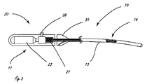
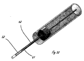
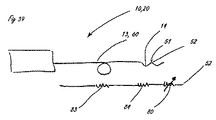
[0010]図1は、体腔の周辺の組織を破壊するように適合された例示的な送達システムを示す。送達システム10は、ハンドル11と、細長い送達部材13とを含む。細長い部材13の遠位部分に関連するのは、遠位送達領域14である。遠位送達領域14は、1つまたは複数の流体制御部16を含む。ハンドル11は、少なくとも1つの送達部材作動要素12(2つが示されている)と、少なくとも1つの流体制御部作動要素15(2つが示されている)とを含む。送達部材作動要素12は、遠位送達領域14を含めて送達部材13を体内の標的場所に向けて進めるように適合されることができる。送達部材作動要素12は、送達構成と1つまたは複数の処置構成の間で遠位送達領域14を再構成するように適合されることもできる。流体制御部作動要素15は、周辺組織リモデリングを遂行するように流体制御部16を作動するように適合される。
[0010] FIG. 1 illustrates an exemplary delivery system adapted to disrupt tissue surrounding a body cavity.
[0011]図2は、流体システムを有する例示的な送達システムを示す。システム20は、ハンドル11とは別個の構成要素のアセンブリとして表されているが、流体システム20は、ハンドル11内部に組み込まれることができる。流体システム20は、流体貯蔵部21と、任意選択の追加の貯蔵部22とを含む。貯蔵部(複数可)は、流体制御部16(図1を参照)に薬剤を送達するための原動力を提供する圧力源23と接続する。組織破壊は、流体貯蔵部から流体制御部16への薬剤の送達によって媒介される。あるいは、流体制御部作動要素15は、流体システム20内にあってもよい。
[0011] FIG. 2 illustrates an exemplary delivery system having a fluid system. Although the
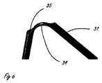
[0012]図3から6は、流体システムを組み込んだ送達システムの例示的な実施形態を示す。図示されている例示的な流体システムは、本明細書における細長い送達部材のいずれかと共に組み込まれることができるが、図3に示されるように、流体システムはハンドル11に組み込まれる。圧力源23は、流体貯蔵部21と流体連通する、CO2カートリッジなどのガスカートリッジを含み、流体貯蔵部21は、流体制御部作動要素として機能する弁38と流体連通する。図3では、送達部材作動要素39は、図4に示される送達構成から図5に示される処置構成または治療構成への遠位送達領域14の再構成を容易にする。遠位送達領域14は、図4に示されるそれぞれの送達構成から図5に示される拡張された構成に再構成されるように適合された複数の拡張可能な管状の要素31を備える。送達構成では、管状の要素は略直線状であり、送達部材13の長手方向軸と略整合する。4つの管状の要素31を備える遠位送達領域14が示されているが、任意の適切な数の要素が組み込まれることができる。管状の要素31は、その遠位端で密封されることができ、外側シース36の遠位部分に固着される。管状の要素31は、流体源と流体連通するポート35を含む。示される実施形態では、ポートは、管状の要素31の遠位端の近位にある管壁の一部分を除去することによって形成される。システムは、遠位送達領域14の近位にあるシース36の一部分の内部に配置される制御部材33(図5を参照)を含む。制御部材33は、シース36の近位部分に対して軸方向に移動可能であり、遠位送達領域の遠位にあるシースおよび管状の要素31に固定される。制御部材33が、送達部材作動要素39の作動などによって近位方向に作動されるとき、管状の要素31の遠位端および近位端が互いに近付くように付勢され、管状の要素31を屈曲領域34で制御部材から径方向外側に屈曲させる。屈曲されるとき、ポート35どうしは接触させられ、または少なくとも遠位送達領域が位置決めされた内腔壁に向けられる。次に、流体または薬剤は、組織を破壊するために流体源からポート35を通って送達されることができ、これについては上記でより詳細に説明した。治療が行われた後、制御部材33は、管状の要素の両端を互いから遠ざけるようにシース36の近位部分に対して遠位に前進させられ、管状の要素を送達構成に戻して再構成する。管状の要素が拡張された構成にあるとき、排出ポート35は、細長い送達部材13の長手方向軸の平面に略垂直な平面に配置される。これより多数または少数の細長い管が遠位送達領域にあることができる。図3から6に示される構成の代替として、ポート35は、ジグザグに配置される(staggered)ことができ、これは、異なる組織破壊治療に適切でありうる。可撓性の管31は、ニチノールなどの任意の適切な可撓性材料から製造されることができる。この実施形態では、制御部材33は内腔を有し、それによって、ガイドワイヤ管腔の機能も提供する。
[0012] FIGS. 3-6 illustrate an exemplary embodiment of a delivery system incorporating a fluid system. The exemplary fluid system shown can be incorporated with any of the elongate delivery members herein, but the fluid system is incorporated into the
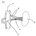
[0013]図7から10は、図3から6に示される例示的なシステムを使用した腎臓44の腎動脈40を取り囲む腎神経叢43のリモデリングの例示的な方法を示す。腎神経叢は、図を簡単にするために2つの神経として示されているが、実際には、腎神経叢は腎動脈を包み込む。遠位送達領域14を有する細長い送達部材13は、大腿動脈または他の適切な場所から、知られている技法を使用して、下行大動脈41に送達され、次に腎動脈40に入る。送達は、従来の手段によって以前に腎動脈に送達されたガイドワイヤ17によって容易にされる。あるいは、操作機能を組み込んだ実施形態の場合、送達は、ガイドワイヤを使用することなく容易にされることができる。または、さらに他の代替実施形態では、送達は、開示が参照により本明細書に組み込まれる、2009年6月24日に出願された米国特許出願第12/823,049号に記載されたカテーテルなどの操作可能なイントロデューサカテーテルを使用するによって容易にされることができる。送達に際して、遠位送達領域14は、送達部材作動要素を作動することによって、図8に示される送達される構成に拡張される。いくつかの実施形態では、作動要素は遠位に前進させられる。圧力源制御要素(図3の要素38を参照)は、それによって稼動され、図9に示される流体51の高速ジェットとして構成された用量の送達を開始する。単一または複数のジェットは、遠位送達領域が任意の所与の場所にある間、送達されることができる。遠位送達領域は、組織拡張制御要素12(図3を参照)を放出する(または、さらに作動する)ことによって新しい場所に移動でき、それによって遠位送達領域を再構成する。次に、遠位送達領域が第2の場所に移動され、それに続いて組織接続部拡張制御要素12によって作動されることができる。送達された流体による影響を受ける組織の量は、各個々の流体ジェットの量、任意の所与の場所に送達されるジェットの数、ならびにジェットが送達される場所の数および密度によって制御されることができる。所望の数のジェットが適切な数の場所に送達された後、送達された流体の振る舞い(action)が、図10に示される影響を受ける量の組織を越えて、本明細書において腎神経と説明される腎神経叢の少なくとも一部分に影響を与えるのに十分に大量の組織に影響を与える。本明細書において説明するシステムのいずれも、図7から10の例示的な方法に示される方法において使用されることができる。
[0013] FIGS. 7-10 illustrate an exemplary method of remodeling the
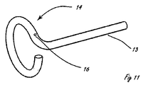
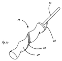
[0014]図11から19は、種々の遠位送達領域14を示す。図11は、細長い送達部材13の延長部である再構成可能な遠位送達領域を表す。図11では、遠位送達領域は、治療構成または拡張された構成において細長い管状の要素を含む。送達構成(図示されず)では、この細長い管状の要素は、略直線状の構成である。送達中に、遠位送達領域14は、細長い送達部材13と略整合し、材料の弾性特性のために、送達カテーテルを出るに際して、図11の構成を想定する。たとえば、遠位送達領域は、ニチノールからなり、送達カテーテルから展開されたときに自己拡張するためにニチノールの超弾性特性を利用することができる。細長い管状の要素は、管状の要素と内腔壁の間の接触領域が平面にほぼ位置し、楕円形または円形の形状を有するように、略円形または楕円形の構成を有する。いくつかの実施形態では、2009年6月24日に出願された、共同所有された係属中の米国特許出願第12/823,049号に示されるデバイスおよび方法を使用しており、引っ張り要素と圧縮要素が互いに相反して動作される。この圧縮要素は、示される形状に圧壊するレーザ切断パターンを組み込む。このような構成では、結果として生じる形状および送達システムは、引っ張る際と、管状の要素の形状を維持する際の両方において、送達軸に沿って著しい剛性度を維持することができる。図11では、遠位送達領域14は、以下でより詳細に説明する少なくとも1つの流体ジェット開口を含む流体制御部16も含む。遠位送達領域14がその送達構成からその処置構成に移行するとき、流体制御部16は、標的組織の内腔壁に押し付けられる。遠位送達領域14は、その送達構成に戻すことによって、または、場合によっては、その処置構成で移動させることによって、ある場所から別の場所に移動されることができる。
[0014] FIGS. 11-19 illustrate various
[0015]図11の組織接続部は、送達軸に垂直な平面にあるループ状の組織接続部により示されているが、別法として、送達軸が存在する平面内にあるように構成されることができる。このような構成は、1つまたは複数の正弦波周期を含む正弦曲線を描く組織接続部からなることができる。さらに、各周期または半周期は、以前の平面から送達軸のまわりに回転された異なる平面に位置することができる。 [0015] The tissue connection of FIG. 11 is illustrated by a looped tissue connection in a plane perpendicular to the delivery axis, but is alternatively configured to be in the plane in which the delivery axis exists. be able to. Such a configuration can consist of a tissue connection that draws a sinusoid comprising one or more sinusoidal periods. Furthermore, each cycle or half cycle can be located in a different plane that has been rotated around the delivery axis from the previous plane.
[0016]図12は、組織と管状の要素の間の接触領域が螺旋状構成を有するように、(図示のような)螺旋状処置構成を有する細長い管状の要素を含む遠位送達領域を示す。図12のデバイスは、図11のデバイスと類似の方法で作動されるように適合される。図13は、図12のデバイスと類似の方法で作動されるように適合された第1の管状の要素と第2の管状の要素とを含む遠位送達領域14を示す。図13の細長い管状の要素は、拡張されたときに螺旋状構成を有し、それらと標的内腔との接触領域は螺旋状である。図12および13に示される細長い管状の要素は、複数の流体制御部16を含む。図12および13の拡張された螺旋状構造は、関連するリモデリング要素16を、標的内腔と接触させるように付勢する。図13に記載の複数の細長い要素によって、内腔壁に対する複数の管状の要素からの力は、管状の要素と内腔壁の間のより安定した接触領域を作り出すことができる。
[0016] FIG. 12 shows a distal delivery region comprising an elongate tubular element having a helical treatment configuration (as shown) such that a contact region between tissue and the tubular element has a helical configuration. . The device of FIG. 12 is adapted to be operated in a similar manner as the device of FIG. FIG. 13 shows a
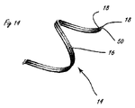
[0017]図14は、遠位送達領域の例示的な一部分を示す。遠位送達領域14は、図12の遠位送達領域の変形形態であり、螺旋状要素は、複数の流体制御部16を組み込んだシャトル弁50の両側に設置された2つのばね要素18を備える。
[0017] FIG. 14 illustrates an exemplary portion of a distal delivery region. The
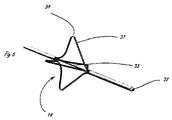
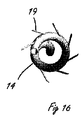
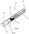
[0018]図15および16は、遠位送達領域の代替実施形態の斜視図および端面図をそれぞれ示す。遠位送達領域14は、略螺旋状の治療構成を有する管状の要素を含み、複数の貫通性リモデリング要素19を含む。リモデリング要素19は、いくつかの異なる方法で組織をリモデリングするために使用されることができる。処置的に、遠位送達領域は、送達構成において遠位送達領域を用いて後退された貫通性リモデリング要素19により標的内腔に送達される。次に、細長い要素は、再構成されて螺旋状構成になる。送達中に後退されたリモデリング要素19は、次に、細長い要素を通って遠位に前進させられ、図15および16に示される構成になる。リモデリング要素は、次に、切断もしくは膨張などの高速ジェット相互作用および/または切断要素もしくは解離(macerating)要素の物理的相互作用、それを通しての組織破壊薬剤の送達、RFエネルギーの送達、またはこれらの任意の組み合わせから生じる機械的損傷のいずれかによって標的組織をリモデリングするために使用されることができる。貫通性リモデリング要素19は、以下で説明するように流体制御部を備えることができる。
[0018] FIGS. 15 and 16 show a perspective view and an end view, respectively, of an alternative embodiment of the distal delivery region. The
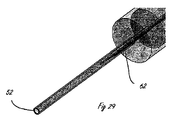
[0019]図17および18は、図3から6に示される遠位送達領域に関する2つの変形形態を示す。両方の設計では、遠位送達領域制御要素37(それを通るガイドワイヤ管腔を有する)は、外側シース36に対して近位に後退され、それによって遠位送達領域14が短縮される。これによって、管状の要素31が拡張し、内腔壁と係合する。図17では、本明細書において説明するように、それぞれの可撓性管は、開口52を含むニードル弁を組み込む。管状の要素31が拡張されると、流体開口52は、移動されて内腔壁と接触するようになる。図17では、外側シース36の一区域が、流体供給ライン65を貫通する弁制御ワイヤ64を示すために除去されている。図18のデバイスは同じように拡張されるが、ニードル弁ではなく(本明細書においてより詳細に説明する)シャトル弁を備える。
[0019] FIGS. 17 and 18 show two variations on the distal delivery region shown in FIGS. 3-6. In both designs, the distal delivery region control element 37 (with a guidewire lumen therethrough) is retracted proximally with respect to the
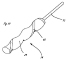
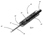
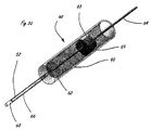
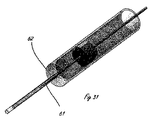
[0020]図18に示される例示的な代替の遠位送達領域は、4つのシャトル弁を組み込んで示されており、このシャトル弁はそれぞれ、弁可動部材57(図21および23を参照)と、弁静止部材58(図21および23を参照)と、複数の開口60とからなる。遠位送達領域を拡張する代替方法は、バルーンを組み込むことである。図19および20は、シャトル弁を組み込んだ2つの例示的な遠位送達領域を示す。両方の実施形態は、バルーンが膨らむと血液を流れさせるように輪郭が形成されたバルーンを備える。血流は、シャトル弁を含む内腔接触帯に隣接する螺旋状の流路内で維持される。図19では、流体制御部60は、バルーン24内部に組み込まれたシャトル弁であり、図20では、流体制御部60は、バルーン上に組み込まれたシャトル弁である。これらの実施形態は、あるいは、従来の非灌流性バルーンを備えることができる。
[0020] The exemplary alternative distal delivery region shown in FIG. 18 is shown incorporating four shuttle valves, each of which includes a valve movable member 57 (see FIGS. 21 and 23) and The valve stationary member 58 (see FIGS. 21 and 23) and a plurality of
[0021]いくつかの状況では、本明細書において説明する送達デバイスは、単一の流体制御部が複数の開口60を作動するように構成されることができる。
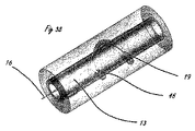
[0022]図21から24は、遠位送達領域内に組み込まれることが可能なシャトル弁に関する2つの変形形態を示す。図21および22の弁(図22は、図21のデバイスの一部分の拡大図である)は、弁の外側部材56上の1つまたは複数の開口52と、マスキング開口53を組み込んだ、外側部材56に対して軸方向に移動可能な内側部材55とを組み込む。開口52は、マスキング開口53より小さい。摺動する内側マスキング開口53が、開口52に隣接する位置に摺動されると、個々の開口52は、選択的に対象とされる。一構成では、部材55および56はそれぞれ、遠位端57および58で密封される。別法として、設計が、マスキング開口53の遠位にある管類の長さが、対象とされた開口の遠位にある開口52のすべてを覆うのに十分に長いようなものであるとき、他の部材に対して移動されるように適合された部材は、開放されたままにされることができる。内側部材55および外側部材56は、内側部材の外径と外側部材の内径が密接に一致するように構成され、それによって、最小の断面積および高い流体抵抗の環状領域が作り出される。これとは別に、またはこれに加えて、内側可動部材またはその区域は、加圧される間に発生する負荷下で拡張し、それによって環状の横断面を減少させ、それによって流体抵抗をさらに増加させるように設計されることができる。
[0021] In some situations, the delivery devices described herein can be configured such that a single fluid control operates
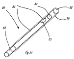
[0022] FIGS. 21-24 show two variations on shuttle valves that can be incorporated into the distal delivery region. The valve of FIGS. 21 and 22 (FIG. 22 is an enlarged view of a portion of the device of FIG. 21) includes an outer member incorporating one or
[0023]図21では、開口53がより小さな所与の開口と整合するように、より大きな開口53を、より小さな開口52に対して移動させることによって、そのより小さな開口52は、選択的に対象指定可能であり、その弁から流れる流体の量を増加させることができる。所与の弁が対象とされるとき、他の弁は対象とされない。この実施形態では、弁は、連続して選択的に対象指定可能であることができる。すなわち、開口53が第1の開口52から第2の開口52に移動されるとき、第1の開口および第2の開口は連続して選択的に対象とされる。あるいは、可動部材53が、その中央内腔によって画定された軸のまわりの回転自由度を許可されるとき、可動部材53は、90度回転し、より小さな開口52を対象とすることなく、これらを通過し、次に対象とされることを意図された開口と整合されると逆方向に90度回転することができる。
[0023] In FIG. 21, by moving the
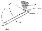
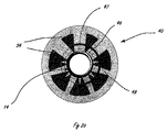
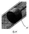
[0024]図23および24は、マスキング開口53が外側静止部材56上にあり、かつ開口52が内側可動部材55上にあるシャトル弁に関する代替変形形態を示す。マスキング開口53は、内側開口52によって対象指定可能な視野(field of view)54を作り出すマスクとしてのさらなる利点に使用されることができる。開口52は、視野54を形成するマスク内部で外側静止部材56の円柱軸のまわりで回転されることができる。視野54は、内腔の周辺の損傷組織のリモデリングされた量の中心を形成する。視野54は、別法として、ジェットと組織との相互作用から生じる組織内のスライスを説明することができる。対象とされることを意図されていないマスキング開口の視野から開口52を回転させることによって、マスク53によって画定された視野54のいかなる選択も、流体送達のために対象とされることができる。
[0024] FIGS. 23 and 24 show an alternative variation for a shuttle valve in which the
[0025]いくつかの実施形態では、図23および24ならびに本明細書における他の実施形態に示される視野は、本明細書において説明する組織リモデリング療法によって組織が切断または分離される例示的なパターンを示す。 [0025] In some embodiments, the field of view shown in FIGS. 23 and 24 and other embodiments herein is an exemplary view in which tissue is cut or separated by the tissue remodeling therapy described herein. Indicates a pattern.
[0026]本明細書において説明する開口52は、直径の、または横断面が円形でないときは表面積の範囲内に入ることができる。約1から約20mL/分の範囲の送達流量の場合、約0.127mm(0.005インチ)から約0.0127mm(0.0005インチ)の直径が特に有益である。開口は、流出のピーク速度が最低でも約10m/秒に達するようなサイズにされるべきであり、約75から約150m/秒が、より大きな貫通および糜爛(erosion)の最小化を実現するためにより最適である。いくつかの状況では、約150m/秒より大きな速度が、さらに大きな貫通を達成するうえで有用である。
[0026] The
[0027]本明細書において説明する組織接続手段は、隣接する組織に対する開口の移動を最小限に抑えるように組織と接触する流体開口を安定させる手段を提供する。それによって、流体ジェットの使用に伴う切開のリスクが最小限に抑えられる。さらに、遠位流体制御部を組み込むことによって、薬剤が送達される期間が制御されることができる。1秒またはそれ未満、好ましくは100ミリ秒またはそれ未満の短いバーストで薬剤のジェットを提供することによって、予期されない移動が、直線状の切開ではなく複数の点状の創傷(punctate wound)を生じる。 [0027] The tissue connection means described herein provide a means for stabilizing fluid openings in contact with tissue so as to minimize movement of the opening relative to adjacent tissue. Thereby, the risk of incision associated with the use of a fluid jet is minimized. Furthermore, by incorporating a distal fluid control, the period during which the drug is delivered can be controlled. By providing a jet of drug in a short burst of 1 second or less, preferably 100 milliseconds or less, unexpected movement results in multiple punctate wounds rather than straight incisions .
[0028]本明細書において説明するデバイス内の流体開口に関連する断面積が比較的に小さいことを考慮すると、使用する前に液体薬剤を濾過することおよび/または遠位流体制御部の近位にフィルタを組み込むことは、一般に賢明である。 [0028] Given the relatively small cross-sectional area associated with the fluid opening in the devices described herein, filtering the liquid medicament prior to use and / or proximal of the distal fluid control It is generally sensible to incorporate a filter into
[0029]図25は、図23からのシャトル弁設計と共に組み込まれ、かつ腎動脈40内で拡張された、図12からの螺旋形の遠位送達領域を示す。組織損傷のパターンは、視野54によって示される。図26は、このようなパターンが内腔の軸に垂直に投射されることによって、内腔から遠い重複する濃い適用範囲と内腔に近い重複しない離隔された適用範囲の両方がどのようにして生成されるかを説明する、血流の方向に垂直な図を示す。蛇行(jetting)構造および関連する視野の濃度は、リモデリングされた帯自体が重複する点まで増加することができる。必要とされる関連する濃度および視野は、損傷が発生する特定の方法によって決まる。本明細書において説明するより小さな開口で示されるように、開口の寸法が比較的小さいことを考慮すると、視野54によってもたらされる、開口に近い損傷した組織の量の比は、損傷の量に対してはるかに最小限に抑えられることができる。図示されるように、内腔が腎動脈の内腔である場合、これは、内皮、内膜46、中膜、および外膜47への損傷を最小限に抑えることを意味し、外膜48への広範な損傷を有する。必要に応じて、開口の視野54は、それに対応して中膜47での損傷を増加させるように増加されることができる。上述のように、示される視野のいずれも、シャトル弁23の可動部材を適切に制御することによって任意の順序で対象とされることができる。このようにして、腎神経がより多くまたはより少なく破壊されることができる。
[0029] FIG. 25 shows the helical distal delivery region from FIG. 12 incorporated with the shuttle valve design from FIG. 23 and expanded within the
[0030]図21および23のデバイスは、一度に単一の流体制御部のみが対象とされることができるように、または一度に複数の流体制御部が対象とされることができるように構成されることができる。 [0030] The devices of FIGS. 21 and 23 are configured such that only a single fluid control can be targeted at a time, or multiple fluid controls can be targeted at a time. Can be done.
[0031]図27から32は、送達システムの近位端から稼動され、閉構成における最小漏出または作動されないときの高い流体抵抗を可能にし、開構成において最小流体抵抗を可能にし、弁から計量された用量を提供する機能を提供し、逐次稼動または並行稼動の両方が可能とすることができる例示的なニードル弁の種々の構成および態様を示す。すべての弁は、流体供給区域65内部で軸方向に(前後に)移動されるように適合された弁制御部材64によって稼動され、これらの両方は、ハンドル(図示せず)で終端する。いくつかの例では、計量区域または送達区域66もある。図27から29では、ニードル弁は、供給区域65を介して開口52と流体連通し比較的一定の圧力で維持される加圧流体源によって供給され、供給区域65の中には弁制御要素64がある。弁制御部材64が流体供給区域内に含まれる任意の横断面では、環状領域63として図27に示される、比較的非制限的な流体流れ横断面(relatively non−restrictive fluid flow cross section)がある。流体供給区域の遠位には、送達弁区域66があり、送達弁区域66は、図27から29の実施形態では、供給区域より小さな直径を有する。弁区域と関連するのは、送達区域66内部に配置された針要素61である。針と送達区域内腔の間の隙間は小さく、したがって、針が除去された内腔の流体抵抗と比較して比較的高い流体抵抗を有する狭い制限的な環状領域62を形成する。さらに、供給区域62の流体流れ横断面は、63よりはるかに小さい。たとえば、特定の濃度のETOHおよび水の場合、0.127mm(0.005インチ)内径において長さ1.27cm(0.5インチ)内径0.1016mm(0.004インチ)の針によって作り出される制限的流体流れ横断面は、3100kPa(450psi)/mL/分の流体抵抗を有する。針のない同じ管の対応する抵抗は、約35kPa(5psi)/mL/分である。比較的に、0.381mm(0.015インチ)の外径を有する長さ81.28cm(32インチ)の管および外径0.254mm(0.010インチ)の制御ワイヤによって作り出される供給区域は、対応する約7kPa(1psi)/mL/分の流体抵抗を有する。この例では、開構成におけるシステムの流体抵抗は、閉システムの流体抵抗の約75分の1であり、一定の圧力環境では、閉構成における開放速度(open rate)の約1/75の速度で漏出する。図27および28に表される構成では、開口52は、送達区域66側の密封された遠位端近くに作製される。図29に表される構成では、開口は送達区域の開放遠位端である。
[0031] FIGS. 27-32 are operated from the proximal end of the delivery system and allow minimal fluid leakage in the closed configuration or high fluid resistance when not activated, allow minimal fluid resistance in the open configuration and are metered from the valve. Fig. 2 illustrates various configurations and aspects of an exemplary needle valve that provides the ability to provide a different dose and that can be capable of both sequential or parallel operation. All valves are actuated by a
[0032]
図27から29の例に関する変形形態が図30から32に表されている。図30は、針の端部が送達区域66の内腔のまさに内部に維持された開構成のニードル弁を示す。図31では、弁は、示される制限的流体流れ横断面62の一区域によって部分的に閉鎖される。図32は、供給区域65の端部密封の近位面に当接するガイド69の遠位面によって完全に閉鎖された弁を示す。必要な場合、流体抵抗のさらなる増加は、エラストマーガイド69、または供給区域65上の端部密封の近位面に対して密封するガイド69に対するエラストマー遠位面(elastomeric distal face)を組み込むことによって、完全に閉鎖した位置で達成されることができる。ガイド69は、さらに、大きな流体流れ横断面63を作り出すために軽減されるエリア(relieved area)を組み込む。
[0032]
Variations on the example of FIGS. 27-29 are represented in FIGS. 30-32. FIG. 30 shows the needle valve in an open configuration with the end of the needle maintained just inside the lumen of the
[0033]図33から35は、絞り弁構成の例示的な実施形態を示す。ガイド69は、この構成では、供給区域65の端部とすることができる送達区域66の端部により狭い制限的な環状開口を形成するように構成される。弁制御部材64が近位に作動されるとき、流体は、制限的な流体流れ横断面62全体にわたって漏出し、遠位の計量された量(distal metered volume)67を満たす。この時点で、供給側と送達側の間の流体抵抗は、出口開口52および制限的横断面62に関連する流体抵抗の合計である。弁制御部材64が解放されるとき、横断面62全体の流体流に関連する抵抗はゼロになり、ガイドは送達流体の栓として移動する。ガイドの移動によって、最小の追加流体抵抗がシステムに付与され、それによって、開口52全体の圧力が、ガイドが所定の位置にない場合に見られる圧力と同等のレベルに達する。この状態は、図35に示されるようにガイドが送達区域66の遠位密封された端部68にぶつかるまで引き続き有効である。この時点で、流出抵抗は、再び、制限的な流体流れ横断面62および開口52に関連する流出抵抗となる。このようにして、送達される量(内膜を貫通する、高圧下で高速に送達された量)は、その放出前にガイド栓の遠位に配置された量である。したがって、送達された量は、調整および制御でき、調整可能であることができる。必要とされる場合、充填周期中にガイドが抜去される速度は、ガイド69全体にわたって生成される最小負圧があるように、制限的な流体流れ横断面62全体の予想流体流の速度と一致されることができる。この構成は、制御要素全体にわたる流体抵抗は一定を維持するが制御要素の位置が変更できるという点で、他の制御要素と異なるように挙動する。図示されるように、ガイド69の行程は、その止め具として作用する遠位端密封68からのガイドの近位変位の量によって定義される。示されていない一代替実施形態では、ガイド69の変位は、代替機構によって制御されることができ、ガイドの変位は、端部密封68の近位で終わることができる。
[0033] FIGS. 33-35 illustrate an exemplary embodiment of a throttle valve configuration.
[0034]図36および37は、腎動脈40の区域内に展開された図15および16の遠位送達領域を示す。図36では、遠位送達領域14のまさに遠位にある細長い送達部材13の端部は、血管の中央に位置することができる。貫通性リモデリング要素19は、遠位送達領域内での非展開構成から展開状態に展開され、血管の内膜層46および内側層47を貫通して、外膜層48で終端する。リモデリングされた組織45の複数の量は、外膜を螺旋状に通過し、1つは神経43と交差する。図37は、主要な量(primary volume)のリモデリングされた組織が内膜層および外膜層を越えて生じることが理解できる、血管の血流の軸に垂直な図を示す。
[0034] FIGS. 36 and 37 show the distal delivery region of FIGS. 15 and 16 deployed within the area of the
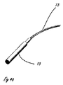
[0035]図38に示されるさらに別の実施形態では、貫通性リモデリング要素19は針である。この針は、螺旋構成を有し、送達システムの送達区域13の外側シースによって含まれる(図示されず)間、送達される。この構成では、送達区域の外側シースは、ばね要素を直線構成で維持するのに十分な剛性を有する。送達に際して、リモデリング要素は、リモデリング要素の遠位端が血管壁に入るまで、送達システムの外側シースの遠位端から遠位に押し出される。次に、リモデリング要素は捻られ、これが、あらかじめ設定された螺旋状構成と組み合わさって、リモデリング要素16を外膜層内部で血管の周囲で回らせる。リモデリング要素は、いくつかの異なる構成からなることができる。これらの構成の多くでは、リモデリング要素は、周囲組織を焼灼するのに十分なエネルギーを送達するためにRFにより動力が供給できる導体である。あるいは、リモデリング要素は、周囲組織に電気穿孔処理を行うという方法で動力が供給されることができる。リモデリング要素は、さらに、アブレーション薬剤(本明細書において説明する)が多孔質構造によって送達できるように多孔性とすることができる。あるいは、リモデリング要素は、アブレーション薬剤を塗布されてもよい。リモデリング要素がその壁にまたはこれを通してアブレーション薬剤を送達するために使用され、かつ導電性である実施形態では、電気穿孔機能(electroporative capability)は、送達されるアブレーション用化合物の挙動を強化するために使用されることができる。リモデリング要素が針からなる場合、リモデリング要素は、要素が送達された手順とは逆の手順によって除去されるときに、その経路の道にアブレーション要素を残すために使用されることもできる。あるいは、残される物質は、本出願において別の場所で言及されたようなフェライトを含むゲルなどの外部源によって提供されたエネルギーを吸収するように設計された物質とすることができる。
[0035] In yet another embodiment shown in FIG. 38, the penetrating
[0036]高速での流体薬剤の送達を使用する構成のいずれにおいても、圧力は、送達周期間で調整されることができる。このようにして、リモデリングされた組織量の量および空間的な特性は、調整されることができる。このような状況で特に価値があるのは、送達された媒体内部での造影剤の導入であり、これは、特定の撮像手段によるリモデリングされた量に関する視覚的なフィードバックを提供する。このような撮像手段としては、CT、MRI、および超音波があるが、これらに限定されない。 [0036] In any configuration that uses fluid drug delivery at high speeds, the pressure can be adjusted between delivery cycles. In this way, the amount and spatial characteristics of the remodeled tissue mass can be adjusted. Of particular value in such situations is the introduction of a contrast agent within the delivered medium, which provides visual feedback regarding the amount remodeled by a particular imaging means. Such imaging means include, but are not limited to, CT, MRI, and ultrasound.
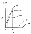
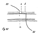
[0037]図42は、シャトル弁として構成された遠位流体制御部を組み込んだ送達システムの比喩的な図を提供し、その流体性能の図は図39に示されている。一般的に上述したように、システムは、送達システム10に供給する流体源かつ圧力源20を備える。送達システムは、遠位送達領域14に供給される流体供給区域を備える細長い送達部材13からなり、遠位送達領域14は、整合の適切な条件下で流体のジェット51が排出される開口52で終端する流体制御部を備える。図40は、送達システムの抵抗流体特性に関する比喩的な図である。要素は、細長い送達部材13内部に含まれる流体源83の流体抵抗、組織接続部分84内部の流路の流体抵抗、および制御ポート80の流体抵抗である。これらの要素のそれぞれは、この図には示されていない関連する容量を有する。制御ポートは、制御下での主要な特性である可変抵抗として挙動する。図40および41は、これらの構成要素の抵抗流体性能(resistive fluidic performance)の種々の態様を示す。図40は、流体制御ポート80に関連する抵抗を、その制御要素位置の変位「d」の関数として表し、さらに、システムの供給区域部分83および組織接続部分84それぞれの抵抗を表しており、これらの抵抗は、この構成では直接的に制御可能ではなく、事実上固定されている。マスキング開口53に対するジェット開口52の重要な位置は、変位軸d上に「0」、「a」、および「b」として示される。点「0」は、ジェット出口開口の近位縁部がジェットマスキング開口の縁部と整合する位置に対応する。位置「a」は、ジェット開口の遠位縁部がマスキング開口の遠位縁部と整合する点に対応し、bは、ジェット出口開口の近位縁部が、何らかの距離a−bだけジェットマスキング開口の遠位縁部の遠位にある点を表す。図から理解されるように、シャトル弁流体制御部80の流体抵抗対変位特性は、2つの別個の性能特徴を有する。最初は、ジェット出口開口の断面積に関連する抵抗に等しい不変抵抗82が示される。ジェット開口がマスキング開口から排出されるときに、次第に増加する第2の抵抗81が示される。この抵抗は、距離dが増加するにつれて増加する。図41は、図40に表される抵抗特性および一定の圧力供給と仮定した関数dとして予想される流出速度90の図を示す。流出速度90は、変位「0」から「a」に対する流出の高い一定速度91と、変位「a」から「b」に対する流出の次第に減少する速度92とからなる。変位「0」から「a」によって表される領域はオン状態に対応し、変位「b」はオフ状態に対応する。システム抵抗は、構成要素抵抗の合計になる。示される縮尺は恣意的なものであることを理解されたい。流れおよび抵抗に関するオフ状態とオン状態の差の大きさは、数倍から複数桁である場合がある。
[0037] FIG. 42 provides a metaphorical view of a delivery system incorporating a distal fluid control configured as a shuttle valve, whose fluid performance diagram is shown in FIG. As generally described above, the system includes a fluid source and a
[0038]図43は、シャトル弁がニードル弁によって置換された、図39のシステムを示す。このシステムは、シャトル弁の変形形態について説明した挙動と同様の流体の挙動を示す。しかし、作動および製造に関連する違いが著しいので、以下で説明する。複数の個別かつ選択的に対象指定可能流体制御部を組み込んだシステムでは、シャトル弁に基づくシステムは、上記の図21から24で示されるように、制御要素が2つの部品からなるように構成されることができる。対照的に、ニードル弁および絞り弁の変形形態は、個別に対象指定可能であるそれぞれの弁ごとに、別個の制御要素および関連する制御可能な部材を必要とする。ニードル弁の変形形態では、制御要素80に関連する可変抵抗は、組織接続部84の位置、組織接続部の抵抗、および最も遠位の位置にあるジェット出口開口に映される。このような構成は、複数の弁が制御要素の近位の共通源を必要とするので、連続構成に適さない。
[0038] FIG. 43 shows the system of FIG. 39 with the shuttle valve replaced by a needle valve. This system exhibits fluid behavior similar to that described for the shuttle valve variation. However, the differences related to operation and manufacturing are significant and will be described below. In a system incorporating multiple individually and selectively targetable fluid controls, the shuttle valve based system is configured such that the control element is comprised of two parts, as shown in FIGS. 21-24 above. Can. In contrast, needle valve and throttle valve variants require a separate control element and associated controllable member for each valve that is individually addressable. In a needle valve variation, the variable resistance associated with the
[0039]上述の流体制御部に関連する重要な機構の多くのサイズが小さいことおよびこれらの機構の寸法に対する流体制御部の性能の感受性が最大であることを考慮すると、各流体制御部を連続的におよび/または個別に対象とできることは、送達の均一性が必要とされる場合に特に価値がある。たとえば、個々のデバイスが、各流出の流出抵抗が分かっており、注入周期中の流体送達に関して各流出が同様に挙動するように静的な源の圧力またはオン時間のどちらかまたは両方を調整するために使用されるような方法で較正されることができる。さらに、前述のように、送達される流体媒体は造影剤を含むことができ、オペレータは、視覚情報を使用して源圧力を変更し、貫通の深度、送達される量を調整するための注入の持続時間を変化させ、または標的組織の量を調整するために所与の場所で複数の注入周期を提供することができる。さらに、送達周期は経時的に広がることができ、したがって、初期量が初期に注入され、次に、送達される流体の拡散速度に関する情報が得られるように十分な時間が可能である場合に、追加の量が後で注入され、次いで、組織をリモデリングするのに十分な時間、焼灼するのに十分な焼灼物(ablatant)の濃度がリモデリングされた標的量において維持されるように、追加の量が送達されることができる。 [0039] In view of the small size of many of the important mechanisms associated with the fluid controls described above and the maximal sensitivity of the fluid controller's performance to the dimensions of these mechanisms, each fluid controller is connected in series. The ability to target individually and / or individually is particularly valuable when uniformity of delivery is required. For example, an individual device knows the outflow resistance of each outflow and adjusts either or both of the static source pressure and / or on-time so that each outflow behaves similarly with respect to fluid delivery during the infusion cycle Can be calibrated in a manner such as that used. Further, as described above, the fluid medium to be delivered can include a contrast agent, and the operator can use visual information to change the source pressure and adjust the depth of penetration, the amount delivered. Multiple infusion cycles can be provided at a given location to vary the duration of or adjust the amount of target tissue. In addition, the delivery cycle can spread over time, so if sufficient time is available so that an initial amount is initially injected and then information on the diffusion rate of the fluid to be delivered can be obtained. An additional amount is injected later, and then added so that the concentration of ablatant sufficient to cauterize is maintained at the remodeled target amount for a time sufficient to remodel the tissue. Can be delivered.
[0040]図44は、流体、気体、または機械ロッドが、本明細書において説明する外部励起可能な構成要素、または排出に際してその送達形状と異なる形状に突然なり、その際その近くの組織を損傷し、それによって、組織をリモデリングさせる構成要素を排出するために使用できる組織リモデリングを遂行するためのさらに別の代替形態を表す。図44では、腎動脈40の壁を通して遠位送達領域30から排出した後のばね要素101が示されている。示されるように、複数のばね要素101が遠位送達領域30の2つの別個の位置から排出されている。ばね要素101は、排出周期の後のある時間の間、歯(tine)が共に保持されるように構成されることができる。たとえば、歯は、水溶性結合剤によって共に保持され、気体、油、またはアルコールの担体に注入されることができる。このようにして、ある期間、組織内部に存在するに際して、結合剤は可溶化(solubalize)され、歯は解放される。歯の解放は、歯を取り囲む組織を切断または解離するために使用されることができる。
[0040] FIG. 44 illustrates that a fluid, gas, or mechanical rod suddenly takes a shape that differs from its delivery shape upon ejection, or an externally excitable component as described herein, and thereby damages nearby tissue. And thus represents yet another alternative for performing tissue remodeling that can be used to eject components that cause the tissue to be remodeled. In FIG. 44, the
[0041]針を用いない注入による影響を受ける組織の量が送達時間における注入液(injectate)の空間速度プロファイルおよび時間速度プロファイルによって決まることは、文献に記載されている。特に、ある量の流体を高い初期速度で組織塊に送達することによって、流体を組織に深く貫通させながら、入口点における組織の損傷が最小限に抑えられる。初期貫通後の流出をより低い速度に維持することによって、初期創傷を通して送達される量を増加させることが容易になる。上述の流体送達システムでは、制御機構は、送達システムの遠位領域に組み込まれている。これにより、送達システムが送達圧力に維持され、それによって、出口開口で排出される流体の速度プロファイルに対する長く狭い送達内腔およびシステム容量のフィルタリング効果が最小限に抑えられる。 [0041] It has been described in the literature that the amount of tissue affected by injection without a needle depends on the space velocity profile and time velocity profile of the injectate at the delivery time. In particular, delivering a quantity of fluid to the tissue mass at a high initial velocity minimizes tissue damage at the entry point while allowing fluid to penetrate deeply into the tissue. By maintaining a lower rate of flow after initial penetration, it is easier to increase the amount delivered through the initial wound. In the fluid delivery system described above, the control mechanism is incorporated in the distal region of the delivery system. This maintains the delivery system at the delivery pressure, thereby minimizing the filtering effect of long and narrow delivery lumens and system volume on the velocity profile of the fluid discharged at the outlet opening.
[0042]組織リモデリングデバイスの別の代替実施形態では、切断デバイスまたは解離デバイスは、図36および37の針16が送達されることによって、またはこれらの針16が送達されるように、送達されることができる。このようなデバイスは、図45に表されるように押されると切断する摺動フックまたは単純なブレードとして構成されることができる。さらに、このようなデバイスは、図45の回転可能な切断デバイスが送達される、図46に示される必須リモデリングを容易にするために、アテレクトミーブレードとしてスピンさせられることができる。図47は、図36に記載のデバイスを示す。本明細書において本開示の好ましい実施形態について図示し説明してきたが、このような実施形態が単なる例示として提供されていることは当業者には明らかであろう。本開示から逸脱することなく、多数の変形、変更、および置換が当業者には想到されよう。本明細書において説明する本開示の実施形態に対する種々の代替形態は、本開示を実施する際に用いることができることを理解されたい。
[0042] In another alternative embodiment of the tissue remodeling device, the cutting device or dissociation device is delivered by delivery of the
Claims (64)
複数の流体制御部を備える遠位送達領域を備える医療デバイスと、
前記複数の流体制御部を通る流体の流れを選択的に調整するステップと
を含む方法。 A method for controlling the delivery of fluid from a medical delivery device comprising:
A medical device comprising a distal delivery region comprising a plurality of fluid controls;
Selectively adjusting fluid flow through the plurality of fluid controls.
流体源と連通する流体制御部を備える遠位送達領域を備える医療デバイスであって、前記流体制御部が、第1の開口をその中に有する第1の制御要素と、第2の開口をその中に有する第2の制御要素とを備える、医療デバイスと、
前記遠位送達領域を患者内部の標的場所の近くに位置決めするステップと、
前記流体制御部を通る流体の流れを増加させるために前記複数の開口を移動させて整合させることによって前記流体制御部から放出される前記流体の量を調整するステップと
を含む方法。 A method for adjusting the amount of fluid delivered from a medical device comprising:
A medical device comprising a distal delivery region comprising a fluid control in communication with a fluid source, wherein the fluid control comprises a first control element having a first opening therein and a second opening therein. A medical device comprising a second control element contained therein;
Positioning the distal delivery region near a target location within a patient;
Adjusting the amount of fluid released from the fluid control by moving and aligning the plurality of openings to increase the flow of fluid through the fluid control.
内腔壁に穴をあけることなく内腔内部に送達デバイスを位置決めするステップと、
前記送達デバイスから前記内腔壁を通して流体薬剤を送達するステップと、
前記内腔壁の周辺の組織を前記流体薬剤によって損傷するステップと
を含む方法。 A method of periluminal tissue damage comprising:
Positioning the delivery device within the lumen without puncturing the lumen wall;
Delivering a fluid medicament from the delivery device through the lumen wall;
Damaging tissue around the lumen wall with the fluid medicament.
複数の流体制御部を備える遠位領域と、
前記遠位領域を貫通し、前記複数の流体制御部と流体連通する内腔であって、流体源と流体連通するように適合された内腔と
を備え、
前記複数の流体制御部のそれぞれが、前記内腔から前記複数の流体制御部の外部に放出される流体の量を調整するために選択的に対象指定可能であるように適合される、
細長い部材を備える、装置。 A device for releasing fluid in a patient's body,
A distal region comprising a plurality of fluid controls;
A lumen passing through the distal region and in fluid communication with the plurality of fluid controls, the lumen adapted to be in fluid communication with a fluid source;
Each of the plurality of fluid controls is adapted to be selectively targetable to adjust the amount of fluid discharged from the lumen to the outside of the plurality of fluid controls;
An apparatus comprising an elongated member.
第1の開口をその中に有する第1の管状の要素と、
第2の開口をその中に有する第2の管状の要素であって、前記第1の管状の要素内部に配置され、前記第1の管状の要素に対して移動可能であり、流体源と流体連通するように適合された、第2の管状の要素を通る内腔を有する、第2の管状の要素と
を備え、
前記複数の開口が、流体が前記内腔から前記第1の開口および前記第2の開口を通過できる整合された構成を有する、装置。 A device for controllably releasing fluid in a patient's body,
A first tubular element having a first opening therein;
A second tubular element having a second opening therein, the second tubular element being disposed within the first tubular element and movable relative to the first tubular element; a fluid source and a fluid A second tubular element having a lumen through the second tubular element adapted to communicate with the second tubular element;
The apparatus, wherein the plurality of openings have an aligned configuration that allows fluid to pass from the lumen through the first opening and the second opening.
遠位端と、近位端と、前記複数の端部の間にある治療部分とを備える細長い部材を備え、
前記治療部分が、それぞれ送達構成と治療構成とを有する複数の拡張可能な細長い要素を備え、
前記複数の拡張可能な細長い要素のそれぞれが流体制御部を備え、前記送達構成では、前記制御部が第1の方向を向き、前記治療構成では、前記制御部が、第1の方向と異なる第2の方向を向く、装置。 A device for controllably releasing fluid in a patient's body,
An elongate member comprising a distal end, a proximal end, and a treatment portion between the plurality of ends;
The treatment portion comprises a plurality of expandable elongate elements each having a delivery configuration and a treatment configuration;
Each of the plurality of expandable elongate elements comprises a fluid control, wherein in the delivery configuration the control is oriented in a first direction and in the treatment configuration the control is different from the first direction. Device facing in the direction of 2.
Applications Claiming Priority (5)
| Application Number | Priority Date | Filing Date | Title |
|---|---|---|---|
| US31723110P | 2010-03-24 | 2010-03-24 | |
| US61/317,231 | 2010-03-24 | ||
| US32446110P | 2010-04-15 | 2010-04-15 | |
| US61/324,461 | 2010-04-15 | ||
| PCT/US2011/029829 WO2011119857A2 (en) | 2010-03-24 | 2011-03-24 | Intravascular tissue disruption |
Publications (2)
| Publication Number | Publication Date |
|---|---|
| JP2013521995A true JP2013521995A (en) | 2013-06-13 |
| JP2013521995A5 JP2013521995A5 (en) | 2014-05-08 |
Family
ID=44673869
Family Applications (1)
| Application Number | Title | Priority Date | Filing Date |
|---|---|---|---|
| JP2013501491A Pending JP2013521995A (en) | 2010-03-24 | 2011-03-24 | Endovascular tissue destruction |
Country Status (7)
| Country | Link |
|---|---|
| US (3) | US8840601B2 (en) |
| EP (1) | EP2550040A4 (en) |
| JP (1) | JP2013521995A (en) |
| CN (1) | CN102917748B (en) |
| AU (3) | AU2011232335A1 (en) |
| CA (1) | CA2793737A1 (en) |
| WO (1) | WO2011119857A2 (en) |
Cited By (1)
| Publication number | Priority date | Publication date | Assignee | Title |
|---|---|---|---|---|
| JP2016524515A (en) * | 2013-07-22 | 2016-08-18 | ボストン サイエンティフィック サイムド,インコーポレイテッドBoston Scientific Scimed,Inc. | Renal nerve ablation catheter with torsion balloon |
Families Citing this family (154)
| Publication number | Priority date | Publication date | Assignee | Title |
|---|---|---|---|---|
| US6302875B1 (en) | 1996-10-11 | 2001-10-16 | Transvascular, Inc. | Catheters and related devices for forming passageways between blood vessels or other anatomical structures |
| US6702811B2 (en) | 1999-04-05 | 2004-03-09 | Medtronic, Inc. | Ablation catheter assembly with radially decreasing helix and method of use |
| US8150519B2 (en) | 2002-04-08 | 2012-04-03 | Ardian, Inc. | Methods and apparatus for bilateral renal neuromodulation |
| US20070135875A1 (en) | 2002-04-08 | 2007-06-14 | Ardian, Inc. | Methods and apparatus for thermally-induced renal neuromodulation |
| US7653438B2 (en) | 2002-04-08 | 2010-01-26 | Ardian, Inc. | Methods and apparatus for renal neuromodulation |
| US8774922B2 (en) | 2002-04-08 | 2014-07-08 | Medtronic Ardian Luxembourg S.A.R.L. | Catheter apparatuses having expandable balloons for renal neuromodulation and associated systems and methods |
| US20080213331A1 (en) | 2002-04-08 | 2008-09-04 | Ardian, Inc. | Methods and devices for renal nerve blocking |
| US7756583B2 (en) | 2002-04-08 | 2010-07-13 | Ardian, Inc. | Methods and apparatus for intravascularly-induced neuromodulation |
| US20070129761A1 (en) | 2002-04-08 | 2007-06-07 | Ardian, Inc. | Methods for treating heart arrhythmia |
| US7617005B2 (en) | 2002-04-08 | 2009-11-10 | Ardian, Inc. | Methods and apparatus for thermally-induced renal neuromodulation |
| US8347891B2 (en) | 2002-04-08 | 2013-01-08 | Medtronic Ardian Luxembourg S.A.R.L. | Methods and apparatus for performing a non-continuous circumferential treatment of a body lumen |
| US20140018880A1 (en) | 2002-04-08 | 2014-01-16 | Medtronic Ardian Luxembourg S.A.R.L. | Methods for monopolar renal neuromodulation |
| US9636174B2 (en) | 2002-04-08 | 2017-05-02 | Medtronic Ardian Luxembourg S.A.R.L. | Methods for therapeutic renal neuromodulation |
| US20040226556A1 (en) | 2003-05-13 | 2004-11-18 | Deem Mark E. | Apparatus for treating asthma using neurotoxin |
| DE202004021946U1 (en) | 2003-09-12 | 2013-05-29 | Vessix Vascular, Inc. | Selectable eccentric remodeling and / or ablation of atherosclerotic material |
| US8396548B2 (en) | 2008-11-14 | 2013-03-12 | Vessix Vascular, Inc. | Selective drug delivery in a lumen |
| US9713730B2 (en) | 2004-09-10 | 2017-07-25 | Boston Scientific Scimed, Inc. | Apparatus and method for treatment of in-stent restenosis |
| EP1819304B1 (en) | 2004-12-09 | 2023-01-25 | Twelve, Inc. | Aortic valve repair |
| US8019435B2 (en) | 2006-05-02 | 2011-09-13 | Boston Scientific Scimed, Inc. | Control of arterial smooth muscle tone |
| EP2954868A1 (en) | 2006-10-18 | 2015-12-16 | Vessix Vascular, Inc. | Tuned rf energy and electrical tissue characterization for selective treatment of target tissues |
| ES2560006T3 (en) | 2006-10-18 | 2016-02-17 | Vessix Vascular, Inc. | Induction of desirable temperature effects on body tissue |
| JP5559539B2 (en) | 2006-10-18 | 2014-07-23 | べシックス・バスキュラー・インコーポレイテッド | System that induces desirable temperature effects on body tissue |
| US8483831B1 (en) | 2008-02-15 | 2013-07-09 | Holaira, Inc. | System and method for bronchial dilation |
| EP2662046B1 (en) | 2008-05-09 | 2023-03-15 | Nuvaira, Inc. | Systems and assemblies for treating a bronchial tree |
| US9795442B2 (en) | 2008-11-11 | 2017-10-24 | Shifamed Holdings, Llc | Ablation catheters |
| EP2355737B1 (en) | 2008-11-17 | 2021-08-11 | Boston Scientific Scimed, Inc. | Selective accumulation of energy without knowledge of tissue topography |
| CN102481433B (en) * | 2009-06-24 | 2014-12-31 | 施菲姆德控股有限责任公司 | Steerable medical delivery devices and methods of use |
| CN107049479B (en) | 2009-10-27 | 2020-10-16 | 努瓦拉公司 | Delivery device with coolable energy emitting assembly |
| KR101820542B1 (en) | 2009-11-11 | 2018-01-19 | 호라이라 인코포레이티드 | Systems, apparatuses, and methods for treating tissue and controlling stenosis |
| US8911439B2 (en) | 2009-11-11 | 2014-12-16 | Holaira, Inc. | Non-invasive and minimally invasive denervation methods and systems for performing the same |
| JP2013523318A (en) | 2010-04-09 | 2013-06-17 | べシックス・バスキュラー・インコーポレイテッド | Power generation and control equipment for tissue treatment |
| US9192790B2 (en) | 2010-04-14 | 2015-11-24 | Boston Scientific Scimed, Inc. | Focused ultrasonic renal denervation |
| CN103118620B (en) | 2010-05-12 | 2015-09-23 | 施菲姆德控股有限责任公司 | The electrode assemblie of low profile |
| US9655677B2 (en) | 2010-05-12 | 2017-05-23 | Shifamed Holdings, Llc | Ablation catheters including a balloon and electrodes |
| US8473067B2 (en) | 2010-06-11 | 2013-06-25 | Boston Scientific Scimed, Inc. | Renal denervation and stimulation employing wireless vascular energy transfer arrangement |
| US9408661B2 (en) | 2010-07-30 | 2016-08-09 | Patrick A. Haverkost | RF electrodes on multiple flexible wires for renal nerve ablation |
| US9084609B2 (en) | 2010-07-30 | 2015-07-21 | Boston Scientific Scime, Inc. | Spiral balloon catheter for renal nerve ablation |
| US9463062B2 (en) | 2010-07-30 | 2016-10-11 | Boston Scientific Scimed, Inc. | Cooled conductive balloon RF catheter for renal nerve ablation |
| US9358365B2 (en) | 2010-07-30 | 2016-06-07 | Boston Scientific Scimed, Inc. | Precision electrode movement control for renal nerve ablation |
| US9155589B2 (en) | 2010-07-30 | 2015-10-13 | Boston Scientific Scimed, Inc. | Sequential activation RF electrode set for renal nerve ablation |
| US8974451B2 (en) | 2010-10-25 | 2015-03-10 | Boston Scientific Scimed, Inc. | Renal nerve ablation using conductive fluid jet and RF energy |
| EP2632376B1 (en) | 2010-10-25 | 2020-02-12 | Medtronic Ardian Luxembourg S.à.r.l. | Catheter apparatuses having multi-electrode arrays for renal neuromodulation |
| US9220558B2 (en) | 2010-10-27 | 2015-12-29 | Boston Scientific Scimed, Inc. | RF renal denervation catheter with multiple independent electrodes |
| US9028485B2 (en) | 2010-11-15 | 2015-05-12 | Boston Scientific Scimed, Inc. | Self-expanding cooling electrode for renal nerve ablation |
| US9668811B2 (en) | 2010-11-16 | 2017-06-06 | Boston Scientific Scimed, Inc. | Minimally invasive access for renal nerve ablation |
| US9089350B2 (en) | 2010-11-16 | 2015-07-28 | Boston Scientific Scimed, Inc. | Renal denervation catheter with RF electrode and integral contrast dye injection arrangement |
| US9326751B2 (en) | 2010-11-17 | 2016-05-03 | Boston Scientific Scimed, Inc. | Catheter guidance of external energy for renal denervation |
| US9060761B2 (en) | 2010-11-18 | 2015-06-23 | Boston Scientific Scime, Inc. | Catheter-focused magnetic field induced renal nerve ablation |
| US9192435B2 (en) | 2010-11-22 | 2015-11-24 | Boston Scientific Scimed, Inc. | Renal denervation catheter with cooled RF electrode |
| US9023034B2 (en) | 2010-11-22 | 2015-05-05 | Boston Scientific Scimed, Inc. | Renal ablation electrode with force-activatable conduction apparatus |
| US20120157993A1 (en) | 2010-12-15 | 2012-06-21 | Jenson Mark L | Bipolar Off-Wall Electrode Device for Renal Nerve Ablation |
| WO2012100095A1 (en) | 2011-01-19 | 2012-07-26 | Boston Scientific Scimed, Inc. | Guide-compatible large-electrode catheter for renal nerve ablation with reduced arterial injury |
| CN103517731B (en) | 2011-04-08 | 2016-08-31 | 柯惠有限合伙公司 | For removing iontophoresis formula drug delivery system and the method for renal sympathetic nerve and iontophoresis formula drug delivery |
| US9237925B2 (en) | 2011-04-22 | 2016-01-19 | Ablative Solutions, Inc. | Expandable catheter system for peri-ostial injection and muscle and nerve fiber ablation |
| US8663190B2 (en) | 2011-04-22 | 2014-03-04 | Ablative Solutions, Inc. | Expandable catheter system for peri-ostial injection and muscle and nerve fiber ablation |
| TW201242570A (en) | 2011-04-25 | 2012-11-01 | Medtronic Ardian Luxembourg | Apparatus and methods related to constrained deployment of cryogenic balloons for limited cryogenic ablation of vessel walls |
| WO2012151396A2 (en) | 2011-05-03 | 2012-11-08 | Shifamed Holdings, Llc | Steerable delivery sheaths |
| US9579030B2 (en) | 2011-07-20 | 2017-02-28 | Boston Scientific Scimed, Inc. | Percutaneous devices and methods to visualize, target and ablate nerves |
| US9186209B2 (en) | 2011-07-22 | 2015-11-17 | Boston Scientific Scimed, Inc. | Nerve modulation system having helical guide |
| US20130053792A1 (en) | 2011-08-24 | 2013-02-28 | Ablative Solutions, Inc. | Expandable catheter system for vessel wall injection and muscle and nerve fiber ablation |
| US9278196B2 (en) | 2011-08-24 | 2016-03-08 | Ablative Solutions, Inc. | Expandable catheter system for vessel wall injection and muscle and nerve fiber ablation |
| US9056185B2 (en) | 2011-08-24 | 2015-06-16 | Ablative Solutions, Inc. | Expandable catheter system for fluid injection into and deep to the wall of a blood vessel |
| WO2013055826A1 (en) | 2011-10-10 | 2013-04-18 | Boston Scientific Scimed, Inc. | Medical devices including ablation electrodes |
| US9420955B2 (en) | 2011-10-11 | 2016-08-23 | Boston Scientific Scimed, Inc. | Intravascular temperature monitoring system and method |
| WO2013055815A1 (en) | 2011-10-11 | 2013-04-18 | Boston Scientific Scimed, Inc. | Off -wall electrode device for nerve modulation |
| US9364284B2 (en) | 2011-10-12 | 2016-06-14 | Boston Scientific Scimed, Inc. | Method of making an off-wall spacer cage |
| US9079000B2 (en) | 2011-10-18 | 2015-07-14 | Boston Scientific Scimed, Inc. | Integrated crossing balloon catheter |
| EP2768563B1 (en) | 2011-10-18 | 2016-11-09 | Boston Scientific Scimed, Inc. | Deflectable medical devices |
| CN108095821B (en) | 2011-11-08 | 2021-05-25 | 波士顿科学西美德公司 | Orifice renal nerve ablation |
| EP2779929A1 (en) | 2011-11-15 | 2014-09-24 | Boston Scientific Scimed, Inc. | Device and methods for renal nerve modulation monitoring |
| US9119632B2 (en) | 2011-11-21 | 2015-09-01 | Boston Scientific Scimed, Inc. | Deflectable renal nerve ablation catheter |
| US9265969B2 (en) | 2011-12-21 | 2016-02-23 | Cardiac Pacemakers, Inc. | Methods for modulating cell function |
| CA2859989C (en) | 2011-12-23 | 2020-03-24 | Vessix Vascular, Inc. | Methods and apparatuses for remodeling tissue of or adjacent to a body passage |
| US9433760B2 (en) | 2011-12-28 | 2016-09-06 | Boston Scientific Scimed, Inc. | Device and methods for nerve modulation using a novel ablation catheter with polymeric ablative elements |
| US9050106B2 (en) | 2011-12-29 | 2015-06-09 | Boston Scientific Scimed, Inc. | Off-wall electrode device and methods for nerve modulation |
| AU2013212265B2 (en) * | 2012-01-23 | 2017-10-12 | Shifamed Holdings, Llc | Intravascular tissue disruption |
| US10029076B2 (en) | 2012-02-28 | 2018-07-24 | Covidien Lp | Intravascular guidewire |
| US8961550B2 (en) | 2012-04-17 | 2015-02-24 | Indian Wells Medical, Inc. | Steerable endoluminal punch |
| WO2013169927A1 (en) | 2012-05-08 | 2013-11-14 | Boston Scientific Scimed, Inc. | Renal nerve modulation devices |
| US8888773B2 (en) | 2012-05-11 | 2014-11-18 | Medtronic Ardian Luxembourg S.A.R.L. | Multi-electrode catheter assemblies for renal neuromodulation and associated systems and methods |
| WO2014032016A1 (en) | 2012-08-24 | 2014-02-27 | Boston Scientific Scimed, Inc. | Intravascular catheter with a balloon comprising separate microporous regions |
| US8612022B1 (en) | 2012-09-13 | 2013-12-17 | Invatec S.P.A. | Neuromodulation catheters and associated systems and methods |
| CN104780859B (en) | 2012-09-17 | 2017-07-25 | 波士顿科学西美德公司 | Self-positioning electrode system and method for renal regulation |
| WO2014047411A1 (en) | 2012-09-21 | 2014-03-27 | Boston Scientific Scimed, Inc. | System for nerve modulation and innocuous thermal gradient nerve block |
| US10549127B2 (en) | 2012-09-21 | 2020-02-04 | Boston Scientific Scimed, Inc. | Self-cooling ultrasound ablation catheter |
| CN104869930B (en) | 2012-10-10 | 2020-12-25 | 波士顿科学国际有限公司 | Renal neuromodulation apparatus and methods |
| US10881458B2 (en) | 2012-10-29 | 2021-01-05 | Ablative Solutions, Inc. | Peri-vascular tissue ablation catheters |
| US9526827B2 (en) | 2012-10-29 | 2016-12-27 | Ablative Solutions, Inc. | Peri-vascular tissue ablation catheter with support structures |
| US10736656B2 (en) | 2012-10-29 | 2020-08-11 | Ablative Solutions | Method for painless renal denervation using a peri-vascular tissue ablation catheter with support structures |
| US10945787B2 (en) | 2012-10-29 | 2021-03-16 | Ablative Solutions, Inc. | Peri-vascular tissue ablation catheters |
| US9301795B2 (en) | 2012-10-29 | 2016-04-05 | Ablative Solutions, Inc. | Transvascular catheter for extravascular delivery |
| US10226278B2 (en) | 2012-10-29 | 2019-03-12 | Ablative Solutions, Inc. | Method for painless renal denervation using a peri-vascular tissue ablation catheter with support structures |
| US8740849B1 (en) | 2012-10-29 | 2014-06-03 | Ablative Solutions, Inc. | Peri-vascular tissue ablation catheter with support structures |
| US9554849B2 (en) | 2012-10-29 | 2017-01-31 | Ablative Solutions, Inc. | Transvascular method of treating hypertension |
| EP4230162A1 (en) | 2012-11-02 | 2023-08-23 | Neurotronic, Inc. | Chemical ablation formulations and methods of treatments for various diseases |
| EP2934569A1 (en) | 2012-12-21 | 2015-10-28 | Sanofi | Exendin-4 derivatives |
| US9398933B2 (en) | 2012-12-27 | 2016-07-26 | Holaira, Inc. | Methods for improving drug efficacy including a combination of drug administration and nerve modulation |
| WO2014143571A1 (en) | 2013-03-11 | 2014-09-18 | Boston Scientific Scimed, Inc. | Medical devices for modulating nerves |
| US9956033B2 (en) | 2013-03-11 | 2018-05-01 | Boston Scientific Scimed, Inc. | Medical devices for modulating nerves |
| US9808311B2 (en) | 2013-03-13 | 2017-11-07 | Boston Scientific Scimed, Inc. | Deflectable medical devices |
| US9108019B2 (en) | 2013-03-13 | 2015-08-18 | Boston Scientific Limited | Catheter system |
| US9179974B2 (en) | 2013-03-15 | 2015-11-10 | Medtronic Ardian Luxembourg S.A.R.L. | Helical push wire electrode |
| AU2014237950B2 (en) | 2013-03-15 | 2017-04-13 | Boston Scientific Scimed, Inc. | Control unit for use with electrode pads and a method for estimating an electrical leakage |
| US9827039B2 (en) | 2013-03-15 | 2017-11-28 | Boston Scientific Scimed, Inc. | Methods and apparatuses for remodeling tissue of or adjacent to a body passage |
| US10265122B2 (en) | 2013-03-15 | 2019-04-23 | Boston Scientific Scimed, Inc. | Nerve ablation devices and related methods of use |
| CA2908517A1 (en) | 2013-04-08 | 2014-10-16 | Apama Medical, Inc. | Cardiac ablation catheters and methods of use thereof |
| US10098694B2 (en) | 2013-04-08 | 2018-10-16 | Apama Medical, Inc. | Tissue ablation and monitoring thereof |
| US10349824B2 (en) | 2013-04-08 | 2019-07-16 | Apama Medical, Inc. | Tissue mapping and visualization systems |
| JP2016523147A (en) | 2013-06-21 | 2016-08-08 | ボストン サイエンティフィック サイムド,インコーポレイテッドBoston Scientific Scimed,Inc. | Renal denervation balloon catheter with a riding-type electrode support |
| JP2016524949A (en) | 2013-06-21 | 2016-08-22 | ボストン サイエンティフィック サイムド,インコーポレイテッドBoston Scientific Scimed,Inc. | Medical device for renal nerve ablation having a rotatable shaft |
| US9707036B2 (en) | 2013-06-25 | 2017-07-18 | Boston Scientific Scimed, Inc. | Devices and methods for nerve modulation using localized indifferent electrodes |
| US9833283B2 (en) | 2013-07-01 | 2017-12-05 | Boston Scientific Scimed, Inc. | Medical devices for renal nerve ablation |
| CN105377169B (en) | 2013-07-11 | 2019-04-19 | 波士顿科学国际有限公司 | Device and method for neuromodulation |
| EP3019106A1 (en) | 2013-07-11 | 2016-05-18 | Boston Scientific Scimed, Inc. | Medical device with stretchable electrode assemblies |
| US9925001B2 (en) | 2013-07-19 | 2018-03-27 | Boston Scientific Scimed, Inc. | Spiral bipolar electrode renal denervation balloon |
| WO2015013205A1 (en) | 2013-07-22 | 2015-01-29 | Boston Scientific Scimed, Inc. | Medical devices for renal nerve ablation |
| CN105473093B (en) | 2013-08-22 | 2019-02-05 | 波士顿科学国际有限公司 | Flexible circuit with the improved adhesion strength to renal nerve modulation sacculus |
| CN105555218B (en) | 2013-09-04 | 2019-01-15 | 波士顿科学国际有限公司 | With radio frequency (RF) foley's tube rinsed with cooling capacity |
| US20150073515A1 (en) | 2013-09-09 | 2015-03-12 | Medtronic Ardian Luxembourg S.a.r.I. | Neuromodulation Catheter Devices and Systems Having Energy Delivering Thermocouple Assemblies and Associated Methods |
| EP3043733A1 (en) | 2013-09-13 | 2016-07-20 | Boston Scientific Scimed, Inc. | Ablation balloon with vapor deposited cover layer |
| US11246654B2 (en) | 2013-10-14 | 2022-02-15 | Boston Scientific Scimed, Inc. | Flexible renal nerve ablation devices and related methods of use and manufacture |
| WO2015057521A1 (en) | 2013-10-14 | 2015-04-23 | Boston Scientific Scimed, Inc. | High resolution cardiac mapping electrode array catheter |
| AU2014334574B2 (en) | 2013-10-15 | 2017-07-06 | Boston Scientific Scimed, Inc. | Medical device balloon |
| US9770606B2 (en) | 2013-10-15 | 2017-09-26 | Boston Scientific Scimed, Inc. | Ultrasound ablation catheter with cooling infusion and centering basket |
| US10945786B2 (en) | 2013-10-18 | 2021-03-16 | Boston Scientific Scimed, Inc. | Balloon catheters with flexible conducting wires and related methods of use and manufacture |
| EP3060153A1 (en) | 2013-10-25 | 2016-08-31 | Boston Scientific Scimed, Inc. | Embedded thermocouple in denervation flex circuit |
| US9931046B2 (en) | 2013-10-25 | 2018-04-03 | Ablative Solutions, Inc. | Intravascular catheter with peri-vascular nerve activity sensors |
| US9949652B2 (en) | 2013-10-25 | 2018-04-24 | Ablative Solutions, Inc. | Apparatus for effective ablation and nerve sensing associated with denervation |
| US10517666B2 (en) | 2013-10-25 | 2019-12-31 | Ablative Solutions, Inc. | Apparatus for effective ablation and nerve sensing associated with denervation |
| US9877742B2 (en) | 2013-11-14 | 2018-01-30 | Cook Medical Technologies Llc | Thrombectomy catheter with flow directing mechanism |
| WO2015103617A1 (en) | 2014-01-06 | 2015-07-09 | Boston Scientific Scimed, Inc. | Tear resistant flex circuit assembly |
| CN106572881B (en) | 2014-02-04 | 2019-07-26 | 波士顿科学国际有限公司 | Substitution of the heat sensor on bipolar electrode is placed |
| US11000679B2 (en) | 2014-02-04 | 2021-05-11 | Boston Scientific Scimed, Inc. | Balloon protection and rewrapping devices and related methods of use |
| US9579149B2 (en) | 2014-03-13 | 2017-02-28 | Medtronic Ardian Luxembourg S.A.R.L. | Low profile catheter assemblies and associated systems and methods |
| US10736690B2 (en) | 2014-04-24 | 2020-08-11 | Medtronic Ardian Luxembourg S.A.R.L. | Neuromodulation catheters and associated systems and methods |
| US10709490B2 (en) | 2014-05-07 | 2020-07-14 | Medtronic Ardian Luxembourg S.A.R.L. | Catheter assemblies comprising a direct heating element for renal neuromodulation and associated systems and methods |
| CN107106820B (en) | 2014-10-30 | 2021-03-19 | 纽敦力公司 | Chemical ablation and methods for treating various diseases |
| WO2016160694A1 (en) | 2015-03-27 | 2016-10-06 | Shifamed Holdings, Llc | Steerable medical devices, systems, and methods of use |
| AU2016253129A1 (en) | 2015-04-24 | 2017-10-26 | Shifamed Holdings, Llc | Steerable medical devices, systems, and methods of use |
| EP3373794B1 (en) | 2015-11-09 | 2022-01-05 | Kalila Medical, Inc. | Steering assemblies for medical devices |
| EP3376936B1 (en) | 2015-11-16 | 2024-01-03 | Boston Scientific Scimed, Inc. | Energy delivery devices |
| JP6997086B2 (en) * | 2015-11-27 | 2022-01-17 | サノフィ-アベンティス・ドイチュラント・ゲゼルシャフト・ミット・ベシュレンクテル・ハフツング | Automatic injection device |
| EP3634528B1 (en) | 2017-06-07 | 2023-06-07 | Shifamed Holdings, LLC | Intravascular fluid movement devices, systems, and methods of use |
| US10857020B2 (en) | 2017-09-14 | 2020-12-08 | Olympus Corporation | Gastrointestinal track constricting method |
| EP3710076B1 (en) * | 2017-11-13 | 2023-12-27 | Shifamed Holdings, LLC | Intravascular fluid movement devices, systems, and methods of use |
| US11116561B2 (en) | 2018-01-24 | 2021-09-14 | Medtronic Ardian Luxembourg S.A.R.L. | Devices, agents, and associated methods for selective modulation of renal nerves |
| US10555801B2 (en) | 2018-03-05 | 2020-02-11 | Olympus Corporation | Gastrointestinal-tract constricting method |
| US10561489B2 (en) | 2018-03-05 | 2020-02-18 | Olympus Corporation | Gastrointestinal-tract constricting method |
| US10918454B2 (en) * | 2018-04-02 | 2021-02-16 | Olympus Corporation | Gastrointestinal tract constricting method |
| US10849685B2 (en) | 2018-07-18 | 2020-12-01 | Ablative Solutions, Inc. | Peri-vascular tissue access catheter with locking handle |
| EP3911361A4 (en) * | 2019-01-18 | 2022-10-12 | University of Georgia Research Foundation, Inc. | Salt nanoparticles and compositions and methods of use thereof |
| US11654275B2 (en) | 2019-07-22 | 2023-05-23 | Shifamed Holdings, Llc | Intravascular blood pumps with struts and methods of use and manufacture |
| WO2021062265A1 (en) | 2019-09-25 | 2021-04-01 | Shifamed Holdings, Llc | Intravascular blood pump systems and methods of use and control thereof |
| US20230218866A1 (en) | 2022-01-13 | 2023-07-13 | Orlando Health, Inc. | Centering device for a catheter |
Citations (3)
| Publication number | Priority date | Publication date | Assignee | Title |
|---|---|---|---|---|
| US5792118A (en) * | 1994-03-07 | 1998-08-11 | Kurth; Paul A. | Permanent catheter with an exterior balloon valve and method of using the same |
| JP2004528092A (en) * | 2001-04-13 | 2004-09-16 | トリカーディア,エル.エル.シー. | Syringe system |
| JP2009522010A (en) * | 2005-12-28 | 2009-06-11 | エーエムエス リサーチ コーポレイション | Apparatus, system and related methods for delivering fluid to tissue |
Family Cites Families (186)
| Publication number | Priority date | Publication date | Assignee | Title |
|---|---|---|---|---|
| CA1237482A (en) * | 1984-03-09 | 1988-05-31 | Frank B. Stiles | Catheter for effecting removal of obstructions from a biological duct |
| US4547193A (en) | 1984-04-05 | 1985-10-15 | Angiomedics Incorporated | Catheter having embedded multi-apertured film |
| US4634432A (en) | 1985-05-13 | 1987-01-06 | Nuri Kocak | Introducer sheath assembly |
| US4726382A (en) | 1986-09-17 | 1988-02-23 | The Boc Group, Inc. | Inflatable finger cuff |
| US5041089A (en) | 1987-12-11 | 1991-08-20 | Devices For Vascular Intervention, Inc. | Vascular dilation catheter construction |
| US4890623A (en) | 1988-03-14 | 1990-01-02 | C. R. Bard, Inc. | Biopotential sensing device and method for making |
| US5372138A (en) | 1988-03-21 | 1994-12-13 | Boston Scientific Corporation | Acousting imaging catheters and the like |
| US4985022A (en) | 1988-11-23 | 1991-01-15 | Med Institute, Inc. | Catheter having durable and flexible segments |
| US5779698A (en) | 1989-01-18 | 1998-07-14 | Applied Medical Resources Corporation | Angioplasty catheter system and method for making same |
| US5343860A (en) | 1989-02-06 | 1994-09-06 | Arzco Medical Systems, Inc. | Esophageal recording/pacing catheter with thermistor and cardiac imaging transceiver |
| US4968306A (en) * | 1989-07-07 | 1990-11-06 | Advanced Cardiovascular Systems, Inc. | Intravascular catheter having an adjustable length infusion section to delivery therapeutic fluid |
| US5010895A (en) | 1989-08-03 | 1991-04-30 | Empi, Inc. | Expandable vaginal electrode |
| DE4104092A1 (en) | 1990-02-13 | 1991-08-14 | Christoph Dr Med Rieger | Metal cannula enclosed in outer cannula of flexible plastics - has circumferential slots in wall to increase flexibility |
| US5180376A (en) | 1990-05-01 | 1993-01-19 | Cathco, Inc. | Non-buckling thin-walled sheath for the percutaneous insertion of intraluminal catheters |
| CA2048120A1 (en) * | 1990-08-06 | 1992-02-07 | William J. Drasler | Thrombectomy method and device |
| US5496267A (en) * | 1990-11-08 | 1996-03-05 | Possis Medical, Inc. | Asymmetric water jet atherectomy |
| US5228442A (en) | 1991-02-15 | 1993-07-20 | Cardiac Pathways Corporation | Method for mapping, ablation, and stimulation using an endocardial catheter |
| US5213576A (en) * | 1991-06-11 | 1993-05-25 | Cordis Corporation | Therapeutic porous balloon catheter |
| US5209741A (en) | 1991-07-08 | 1993-05-11 | Endomedix Corporation | Surgical access device having variable post-insertion cross-sectional geometry |
| CA2117088A1 (en) | 1991-09-05 | 1993-03-18 | David R. Holmes | Flexible tubular device for use in medical applications |
| US5524338A (en) | 1991-10-22 | 1996-06-11 | Pi Medical Corporation | Method of making implantable microelectrode |
| US5697882A (en) | 1992-01-07 | 1997-12-16 | Arthrocare Corporation | System and method for electrosurgical cutting and ablation |
| US6277112B1 (en) | 1996-07-16 | 2001-08-21 | Arthrocare Corporation | Methods for electrosurgical spine surgery |
| US5306250A (en) * | 1992-04-02 | 1994-04-26 | Indiana University Foundation | Method and apparatus for intravascular drug delivery |
| US5562720A (en) | 1992-05-01 | 1996-10-08 | Vesta Medical, Inc. | Bipolar/monopolar endometrial ablation device and method |
| US5277201A (en) | 1992-05-01 | 1994-01-11 | Vesta Medical, Inc. | Endometrial ablation apparatus and method |
| US5443470A (en) | 1992-05-01 | 1995-08-22 | Vesta Medical, Inc. | Method and apparatus for endometrial ablation |
| US5311866A (en) | 1992-09-23 | 1994-05-17 | Endocardial Therapeutics, Inc. | Heart mapping catheter |
| US5309910A (en) | 1992-09-25 | 1994-05-10 | Ep Technologies, Inc. | Cardiac mapping and ablation systems |
| EP0590431B1 (en) | 1992-09-30 | 1999-02-03 | Cardiac Pacemakers, Inc. | A foldable defibrillation patch electrode with a conductor-free zone which acts as a hinge |
| WO1994007446A1 (en) | 1992-10-05 | 1994-04-14 | Boston Scientific Corporation | Device and method for heating tissue |
| US5336178A (en) * | 1992-11-02 | 1994-08-09 | Localmed, Inc. | Intravascular catheter with infusion array |
| CA2114988A1 (en) | 1993-02-05 | 1994-08-06 | Matthew O'boyle | Ultrasonic angioplasty balloon catheter |
| WO1994021320A1 (en) * | 1993-03-15 | 1994-09-29 | Advanced Cardiovascular Systems, Inc. | Fluid delivery catheter |
| US5893847A (en) | 1993-03-16 | 1999-04-13 | Ep Technologies, Inc. | Multiple electrode support structures with slotted hub and hoop spline elements |
| US6749604B1 (en) | 1993-05-10 | 2004-06-15 | Arthrocare Corporation | Electrosurgical instrument with axially-spaced electrodes |
| US5571088A (en) | 1993-07-01 | 1996-11-05 | Boston Scientific Corporation | Ablation catheters |
| US5860974A (en) | 1993-07-01 | 1999-01-19 | Boston Scientific Corporation | Heart ablation catheter with expandable electrode and method of coupling energy to an electrode on a catheter shaft |
| DE69432148T2 (en) | 1993-07-01 | 2003-10-16 | Boston Scient Ltd | CATHETER FOR IMAGE DISPLAY, DISPLAY OF ELECTRICAL SIGNALS AND ABLATION |
| US5630837A (en) | 1993-07-01 | 1997-05-20 | Boston Scientific Corporation | Acoustic ablation |
| WO1995005212A2 (en) | 1993-08-11 | 1995-02-23 | Electro-Catheter Corporation | Improved ablation electrode |
| US5575810A (en) | 1993-10-15 | 1996-11-19 | Ep Technologies, Inc. | Composite structures and methods for ablating tissue to form complex lesion patterns in the treatment of cardiac conditions and the like |
| US5991650A (en) | 1993-10-15 | 1999-11-23 | Ep Technologies, Inc. | Surface coatings for catheters, direct contacting diagnostic and therapeutic devices |
| US5599345A (en) | 1993-11-08 | 1997-02-04 | Zomed International, Inc. | RF treatment apparatus |
| US5531679A (en) * | 1994-03-14 | 1996-07-02 | Schulman; Joseph H. | Fluidic infusion system for catheter or probe |
| US5575788A (en) | 1994-06-24 | 1996-11-19 | Stuart D. Edwards | Thin layer ablation apparatus |
| US5681308A (en) | 1994-06-24 | 1997-10-28 | Stuart D. Edwards | Ablation apparatus for cardiac chambers |
| US5505730A (en) | 1994-06-24 | 1996-04-09 | Stuart D. Edwards | Thin layer ablation apparatus |
| US5735846A (en) | 1994-06-27 | 1998-04-07 | Ep Technologies, Inc. | Systems and methods for ablating body tissue using predicted maximum tissue temperature |
| US6572609B1 (en) | 1999-07-14 | 2003-06-03 | Cardiofocus, Inc. | Phototherapeutic waveguide apparatus |
| US6423055B1 (en) | 1999-07-14 | 2002-07-23 | Cardiofocus, Inc. | Phototherapeutic wave guide apparatus |
| US5626564A (en) * | 1995-03-31 | 1997-05-06 | Creighton University | Adjustable sideholes catheter |
| US6283951B1 (en) * | 1996-10-11 | 2001-09-04 | Transvascular, Inc. | Systems and methods for delivering drugs to selected locations within the body |
| NL1001890C2 (en) | 1995-12-13 | 1997-06-17 | Cordis Europ | Catheter with plate-shaped electrode array. |
| US7452358B2 (en) | 1996-01-05 | 2008-11-18 | Thermage, Inc. | RF electrode assembly for handpiece |
| US7473251B2 (en) | 1996-01-05 | 2009-01-06 | Thermage, Inc. | Methods for creating tissue effect utilizing electromagnetic energy and a reverse thermal gradient |
| US20030212393A1 (en) | 1996-01-05 | 2003-11-13 | Knowlton Edward W. | Handpiece with RF electrode and non-volatile memory |
| US5836874A (en) | 1996-04-08 | 1998-11-17 | Ep Technologies, Inc. | Multi-function electrode structures for electrically analyzing and heating body tissue |
| US5871483A (en) | 1996-01-19 | 1999-02-16 | Ep Technologies, Inc. | Folding electrode structures |
| US5846239A (en) | 1996-04-12 | 1998-12-08 | Ep Technologies, Inc. | Tissue heating and ablation systems and methods using segmented porous electrode structures |
| US5925038A (en) | 1996-01-19 | 1999-07-20 | Ep Technologies, Inc. | Expandable-collapsible electrode structures for capacitive coupling to tissue |
| US5853411A (en) | 1996-01-19 | 1998-12-29 | Ep Technologies, Inc. | Enhanced electrical connections for electrode structures |
| US5879348A (en) | 1996-04-12 | 1999-03-09 | Ep Technologies, Inc. | Electrode structures formed from flexible, porous, or woven materials |
| US5961513A (en) | 1996-01-19 | 1999-10-05 | Ep Technologies, Inc. | Tissue heating and ablation systems and methods using porous electrode structures |
| US5846238A (en) | 1996-01-19 | 1998-12-08 | Ep Technologies, Inc. | Expandable-collapsible electrode structures with distal end steering or manipulation |
| US6292689B1 (en) | 1996-04-17 | 2001-09-18 | Imagyn Medical Technologies California, Inc. | Apparatus and methods of bioelectrical impedance analysis of blood flow |
| US6464697B1 (en) | 1998-02-19 | 2002-10-15 | Curon Medical, Inc. | Stomach and adjoining tissue regions in the esophagus |
| US5904651A (en) | 1996-10-28 | 1999-05-18 | Ep Technologies, Inc. | Systems and methods for visualizing tissue during diagnostic or therapeutic procedures |
| US5976178A (en) | 1996-11-07 | 1999-11-02 | Vascular Science Inc. | Medical grafting methods |
| US5800408A (en) * | 1996-11-08 | 1998-09-01 | Micro Therapeutics, Inc. | Infusion device for distributing infusate along an elongated infusion segment |
| US6071279A (en) | 1996-12-19 | 2000-06-06 | Ep Technologies, Inc. | Branched structures for supporting multiple electrode elements |
| US6024740A (en) | 1997-07-08 | 2000-02-15 | The Regents Of The University Of California | Circumferential ablation device assembly |
| US6012457A (en) | 1997-07-08 | 2000-01-11 | The Regents Of The University Of California | Device and method for forming a circumferential conduction block in a pulmonary vein |
| US6635027B1 (en) * | 1997-05-19 | 2003-10-21 | Micro Therepeutics, Inc. | Method and apparatus for intramural delivery of a substance |
| US5882332A (en) | 1997-06-06 | 1999-03-16 | Wijay; Bandula | Drug infusion catheter and method |
| WO1999000060A1 (en) | 1997-06-26 | 1999-01-07 | Advanced Coronary Intervention | Electrosurgical catheter for resolving obstructions by radio frequency ablation |
| US5938660A (en) | 1997-06-27 | 1999-08-17 | Daig Corporation | Process and device for the treatment of atrial arrhythmia |
| US5888577A (en) | 1997-06-30 | 1999-03-30 | Procath Corporation | Method for forming an electrophysiology catheter |
| US6164283A (en) | 1997-07-08 | 2000-12-26 | The Regents Of The University Of California | Device and method for forming a circumferential conduction block in a pulmonary vein |
| US6500174B1 (en) | 1997-07-08 | 2002-12-31 | Atrionix, Inc. | Circumferential ablation device assembly and methods of use and manufacture providing an ablative circumferential band along an expandable member |
| US6869431B2 (en) | 1997-07-08 | 2005-03-22 | Atrionix, Inc. | Medical device with sensor cooperating with expandable member |
| US6514249B1 (en) | 1997-07-08 | 2003-02-04 | Atrionix, Inc. | Positioning system and method for orienting an ablation element within a pulmonary vein ostium |
| US6652515B1 (en) | 1997-07-08 | 2003-11-25 | Atrionix, Inc. | Tissue ablation device assembly and method for electrically isolating a pulmonary vein ostium from an atrial wall |
| US6102907A (en) | 1997-08-15 | 2000-08-15 | Somnus Medical Technologies, Inc. | Apparatus and device for use therein and method for ablation of tissue |
| US6200312B1 (en) | 1997-09-11 | 2001-03-13 | Vnus Medical Technologies, Inc. | Expandable vein ligator catheter having multiple electrode leads |
| US6258084B1 (en) | 1997-09-11 | 2001-07-10 | Vnus Medical Technologies, Inc. | Method for applying energy to biological tissue including the use of tumescent tissue compression |
| BR9813935A (en) | 1997-11-07 | 2000-09-19 | Salviac Ltd | Vascular filtration devices for removing embolic material from body fluids |
| US6203513B1 (en) * | 1997-11-20 | 2001-03-20 | Optonol Ltd. | Flow regulating implant, method of manufacture, and delivery device |
| US6875193B1 (en) * | 1998-02-06 | 2005-04-05 | Possis Medical, Inc. | Rapid exchange fluid jet thrombectomy device and method |
| US6142993A (en) | 1998-02-27 | 2000-11-07 | Ep Technologies, Inc. | Collapsible spline structure using a balloon as an expanding actuator |
| US6558378B2 (en) | 1998-05-05 | 2003-05-06 | Cardiac Pacemakers, Inc. | RF ablation system and method having automatic temperature control |
| US6163726A (en) | 1998-09-21 | 2000-12-19 | The General Hospital Corporation | Selective ablation of glandular tissue |
| US6123718A (en) | 1998-11-02 | 2000-09-26 | Polymerex Medical Corp. | Balloon catheter |
| US6325797B1 (en) | 1999-04-05 | 2001-12-04 | Medtronic, Inc. | Ablation catheter and method for isolating a pulmonary vein |
| JP2002542876A (en) | 1999-04-29 | 2002-12-17 | ソムナス メディカル テクノロジーズ インコーポレイテッド | Equipment for tissue cutting |
| US6595989B1 (en) | 1999-05-11 | 2003-07-22 | Atrionix, Inc. | Balloon anchor wire |
| AU5595300A (en) | 1999-06-02 | 2000-12-18 | Microheart, Inc. | Devices and methods for delivering a drug |
| US7004923B2 (en) * | 1999-07-19 | 2006-02-28 | I-Flow Corporation | Catheter for uniform delivery of medication |
| EP1229829B1 (en) | 1999-11-10 | 2008-01-09 | Cytyc Surgical Products | System for detecting perforations in a body cavity |
| US6344027B1 (en) | 1999-12-08 | 2002-02-05 | Scimed Life Systems, Inc. | Needle-less injection apparatus and method |
| WO2001064123A2 (en) | 2000-02-29 | 2001-09-07 | Johns Hopkins University | Circumferential pulmonary vein ablation using a laser and fiberoptic balloon catheter |
| US6635054B2 (en) | 2000-07-13 | 2003-10-21 | Transurgical, Inc. | Thermal treatment methods and apparatus with focused energy application |
| US6679879B2 (en) * | 2000-08-16 | 2004-01-20 | John H. Shadduck | Electrical discharge catheter system for extracting emboli in endovascular interventions |
| CA2324045A1 (en) | 2000-10-20 | 2002-04-20 | Universite De Sherbrooke | No-needle syringe for the subcutaneous injection of medicated powders |
| US6743226B2 (en) | 2001-02-09 | 2004-06-01 | Cosman Company, Inc. | Adjustable trans-urethral radio-frequency ablation |
| US6771996B2 (en) | 2001-05-24 | 2004-08-03 | Cardiac Pacemakers, Inc. | Ablation and high-resolution mapping catheter system for pulmonary vein foci elimination |
| US6814730B2 (en) | 2001-10-09 | 2004-11-09 | Hong Li | Balloon catheters for non-continuous lesions |
| AU2002363103B2 (en) * | 2001-10-24 | 2008-10-16 | Med-El Elektromedizinische Gerate Ges.M.B.H. | Implantable fluid delivery apparatuses and implantable electrode |
| US7286866B2 (en) | 2001-11-05 | 2007-10-23 | Ge Medical Systems Global Technology Company, Llc | Method, system and computer product for cardiac interventional procedure planning |
| US7226448B2 (en) | 2001-12-04 | 2007-06-05 | Estech, Inc. (Endoscopic Technologies, Inc.) | Cardiac treatment devices and methods |
| EP2327954A1 (en) | 2002-01-11 | 2011-06-01 | The General Hospital Corporation | Apparatus for OCT imaging with axial line focus for improved resolution and depth of field |
| US7346381B2 (en) | 2002-11-01 | 2008-03-18 | Ge Medical Systems Global Technology Company Llc | Method and apparatus for medical intervention procedure planning |
| US20070135875A1 (en) | 2002-04-08 | 2007-06-14 | Ardian, Inc. | Methods and apparatus for thermally-induced renal neuromodulation |
| US7617005B2 (en) | 2002-04-08 | 2009-11-10 | Ardian, Inc. | Methods and apparatus for thermally-induced renal neuromodulation |
| US8774913B2 (en) | 2002-04-08 | 2014-07-08 | Medtronic Ardian Luxembourg S.A.R.L. | Methods and apparatus for intravasculary-induced neuromodulation |
| US8145317B2 (en) | 2002-04-08 | 2012-03-27 | Ardian, Inc. | Methods for renal neuromodulation |
| US7853333B2 (en) | 2002-04-08 | 2010-12-14 | Ardian, Inc. | Methods and apparatus for multi-vessel renal neuromodulation |
| US8175711B2 (en) | 2002-04-08 | 2012-05-08 | Ardian, Inc. | Methods for treating a condition or disease associated with cardio-renal function |
| US6978174B2 (en) | 2002-04-08 | 2005-12-20 | Ardian, Inc. | Methods and devices for renal nerve blocking |
| US7620451B2 (en) | 2005-12-29 | 2009-11-17 | Ardian, Inc. | Methods and apparatus for pulsed electric field neuromodulation via an intra-to-extravascular approach |
| US8131371B2 (en) | 2002-04-08 | 2012-03-06 | Ardian, Inc. | Methods and apparatus for monopolar renal neuromodulation |
| US8145316B2 (en) | 2002-04-08 | 2012-03-27 | Ardian, Inc. | Methods and apparatus for renal neuromodulation |
| US7653438B2 (en) | 2002-04-08 | 2010-01-26 | Ardian, Inc. | Methods and apparatus for renal neuromodulation |
| US7162303B2 (en) | 2002-04-08 | 2007-01-09 | Ardian, Inc. | Renal nerve stimulation method and apparatus for treatment of patients |
| US8150519B2 (en) | 2002-04-08 | 2012-04-03 | Ardian, Inc. | Methods and apparatus for bilateral renal neuromodulation |
| US7756583B2 (en) | 2002-04-08 | 2010-07-13 | Ardian, Inc. | Methods and apparatus for intravascularly-induced neuromodulation |
| US20030236443A1 (en) | 2002-04-19 | 2003-12-25 | Cespedes Eduardo Ignacio | Methods and apparatus for the identification and stabilization of vulnerable plaque |
| US6808524B2 (en) | 2002-09-16 | 2004-10-26 | Prorhythm, Inc. | Balloon alignment and collapsing system |
| US6780183B2 (en) | 2002-09-16 | 2004-08-24 | Biosense Webster, Inc. | Ablation catheter having shape-changing balloon |
| AU2003300779A1 (en) * | 2002-09-20 | 2004-05-04 | Flowmedica, Inc. | Catheter system for renal therapy |
| US7048733B2 (en) | 2003-09-19 | 2006-05-23 | Baylis Medical Company Inc. | Surgical perforation device with curve |
| US20040172084A1 (en) | 2003-02-03 | 2004-09-02 | Knudson Mark B. | Method and apparatus for treatment of gastro-esophageal reflux disease (GERD) |
| WO2004086082A1 (en) | 2003-03-27 | 2004-10-07 | Koninklijke Philips Electronics N.V. | Guidance of invasive medical devices by wide view three dimensional ultrasonic imaging |
| KR20130138867A (en) | 2003-06-06 | 2013-12-19 | 더 제너럴 하스피탈 코포레이션 | Process and apparatus for a wavelength tunning source |
| EP1663375A4 (en) * | 2003-09-08 | 2007-04-04 | Ash Access Technology Inc | Anti-clotting indwelling catheter |
| DE202004021946U1 (en) | 2003-09-12 | 2013-05-29 | Vessix Vascular, Inc. | Selectable eccentric remodeling and / or ablation of atherosclerotic material |
| US7234225B2 (en) | 2003-09-22 | 2007-06-26 | St. Jude Medical, Atrial Fibrillation Division, Inc. | Method for manufacturing medical device having embedded traces and formed electrodes |
| US7238180B2 (en) | 2003-10-30 | 2007-07-03 | Medicalcv Inc. | Guided ablation with end-fire fiber |
| US7232437B2 (en) | 2003-10-30 | 2007-06-19 | Medical Cv, Inc. | Assessment of lesion transmurality |
| WO2005044124A1 (en) | 2003-10-30 | 2005-05-19 | Medical Cv, Inc. | Apparatus and method for laser treatment |
| US7238179B2 (en) | 2003-10-30 | 2007-07-03 | Medical Cv, Inc. | Apparatus and method for guided ablation treatment |
| FR2861997A1 (en) | 2003-11-06 | 2005-05-13 | Fred Zacouto | Cardiac muscle stimulation device e.g. defibrillator, for use during tachycardia treatment, has impulse generator that sends stimulation pulse without delay at end of refractory period |
| US7220269B1 (en) * | 2003-11-06 | 2007-05-22 | Possis Medical, Inc. | Thrombectomy catheter system with occluder and method of using same |
| US7150745B2 (en) | 2004-01-09 | 2006-12-19 | Barrx Medical, Inc. | Devices and methods for treatment of luminal tissue |
| US7371231B2 (en) | 2004-02-02 | 2008-05-13 | Boston Scientific Scimed, Inc. | System and method for performing ablation using a balloon |
| US7998060B2 (en) | 2004-04-19 | 2011-08-16 | The Invention Science Fund I, Llc | Lumen-traveling delivery device |
| US7510555B2 (en) | 2004-05-07 | 2009-03-31 | Therm Med, Llc | Enhanced systems and methods for RF-induced hyperthermia |
| US7481808B2 (en) | 2004-06-30 | 2009-01-27 | Ethicon, Inc. | Flexible electrode device and surgical apparatus equipped with same |
| JP4995720B2 (en) | 2004-07-02 | 2012-08-08 | ザ ジェネラル ホスピタル コーポレイション | Endoscopic imaging probe with double clad fiber |
| JP5215664B2 (en) | 2004-09-10 | 2013-06-19 | ザ ジェネラル ホスピタル コーポレイション | System and method for optical coherence imaging |
| EP1804638B1 (en) | 2004-09-29 | 2012-12-19 | The General Hospital Corporation | System and method for optical coherence imaging |
| US7937143B2 (en) | 2004-11-02 | 2011-05-03 | Ardian, Inc. | Methods and apparatus for inducing controlled renal neuromodulation |
| JP5623692B2 (en) | 2004-11-02 | 2014-11-12 | ザ ジェネラル ホスピタル コーポレイション | Optical fiber rotator, optical system and method for sample imaging |
| US20090240249A1 (en) | 2004-11-08 | 2009-09-24 | Cardima, Inc. | System and Method for Performing Ablation and Other Medical Procedures Using An Electrode Array with Flexible Circuit |
| US20060100618A1 (en) | 2004-11-08 | 2006-05-11 | Cardima, Inc. | System and method for performing ablation and other medical procedures using an electrode array with flex circuit |
| US7468062B2 (en) | 2004-11-24 | 2008-12-23 | Ablation Frontiers, Inc. | Atrial ablation catheter adapted for treatment of septal wall arrhythmogenic foci and method of use |
| US7429261B2 (en) | 2004-11-24 | 2008-09-30 | Ablation Frontiers, Inc. | Atrial ablation catheter and method of use |
| US7517338B2 (en) * | 2005-01-21 | 2009-04-14 | Boston Scientific Scimed, Inc. | Delivery of therapeutic through multiple delivery members |
| US20110077579A1 (en) * | 2005-03-24 | 2011-03-31 | Harrison William V | Cochlear implant with localized fluid transport |
| US7618393B2 (en) | 2005-05-03 | 2009-11-17 | Pharmajet, Inc. | Needle-less injector and method of fluid delivery |
| US20070060888A1 (en) * | 2005-09-06 | 2007-03-15 | Kerberos Proximal Solutions, Inc. | Methods and apparatus for assisted aspiration |
| US20070213671A1 (en) * | 2005-09-07 | 2007-09-13 | Hiatt Mark J | Infusion catheter system with telescoping cannula |
| US8140170B2 (en) | 2005-09-12 | 2012-03-20 | The Cleveland Clinic Foundation | Method and apparatus for renal neuromodulation |
| US8764820B2 (en) | 2005-11-16 | 2014-07-01 | Edwards Lifesciences Corporation | Transapical heart valve delivery system and method |
| US20090312696A1 (en) | 2005-12-28 | 2009-12-17 | Copa Vincent G | Devices, Systems, and Related Methods for Delivery of Fluid to Tissue |
| US7418169B2 (en) | 2006-02-01 | 2008-08-26 | The General Hospital Corporation | Apparatus for controlling at least one of at least two sections of at least one fiber |
| US9186066B2 (en) | 2006-02-01 | 2015-11-17 | The General Hospital Corporation | Apparatus for applying a plurality of electro-magnetic radiations to a sample |
| DE102006012204A1 (en) | 2006-03-16 | 2007-09-20 | Switech Medical Ag | Fluid medium`s electrical discharge producing device for use in e.g. therapeutic application, has electrodes formed from metallic material including titanium alloy with hardness, where electrical voltage is applied to electrodes in medium |
| US20070244501A1 (en) | 2006-04-18 | 2007-10-18 | Horn Daniel J | Medical balloons |
| JP5559539B2 (en) | 2006-10-18 | 2014-07-23 | べシックス・バスキュラー・インコーポレイテッド | System that induces desirable temperature effects on body tissue |
| US20080119823A1 (en) * | 2006-11-21 | 2008-05-22 | Crank Justin M | Injection Tube for Jet Injection Device |
| US8226293B2 (en) * | 2007-02-22 | 2012-07-24 | Medical Solutions, Inc. | Method and apparatus for measurement and control of temperature for infused liquids |
| US8641711B2 (en) | 2007-05-04 | 2014-02-04 | Covidien Lp | Method and apparatus for gastrointestinal tract ablation for treatment of obesity |
| US8641704B2 (en) | 2007-05-11 | 2014-02-04 | Medtronic Ablation Frontiers Llc | Ablation therapy system and method for treating continuous atrial fibrillation |
| JP4311483B2 (en) * | 2007-08-10 | 2009-08-12 | セイコーエプソン株式会社 | Liquid ejecting apparatus and surgical instrument using the same |
| US9289141B2 (en) | 2007-10-12 | 2016-03-22 | Micropen Technologies Corporation | Apparatus and methods for the measurement of cardiac output |
| WO2009067695A1 (en) | 2007-11-21 | 2009-05-28 | St. Jude Medical, Atrial Fibrillation Division, Inc. | Methods and system for occluding vessels during cardiac ablation |
| US20090254142A1 (en) | 2008-04-08 | 2009-10-08 | Silhouette Medical, Usa | Treating Medical Conditions of Hollow Organs |
| US8206380B2 (en) | 2008-06-13 | 2012-06-26 | Advanced Caridiac Therapeutics Inc. | Method and apparatus for measuring catheter contact force during a medical procedure |
| CA2743140A1 (en) | 2008-11-11 | 2010-05-20 | Shifamed, Llc | Low profile electrode assembly |
| US20110046600A1 (en) | 2008-12-05 | 2011-02-24 | Crank Justin M | Devices, systems, and related methods for delivery of fluid to tissue |
| JP5701219B2 (en) | 2008-12-05 | 2015-04-15 | エーエムエス リサーチ コーポレイション | Devices, systems, and related methods for delivery of fluids to tissue |
| KR101764439B1 (en) | 2009-04-22 | 2017-08-02 | 머케이터 메드시스템즈, 인크. | Use of guanethidine for treating hypertension by local vascular delivery |
| CN102481433B (en) | 2009-06-24 | 2014-12-31 | 施菲姆德控股有限责任公司 | Steerable medical delivery devices and methods of use |
| TWI400103B (en) | 2009-12-03 | 2013-07-01 | Leader Machine Co Ltd | Drug delivery device |
| US20130138082A1 (en) | 2010-03-24 | 2013-05-30 | Amr Salahieh | Intravascular Tissue Disruption |
-
2011
- 2011-03-24 JP JP2013501491A patent/JP2013521995A/en active Pending
- 2011-03-24 CA CA2793737A patent/CA2793737A1/en not_active Abandoned
- 2011-03-24 US US13/071,436 patent/US8840601B2/en active Active
- 2011-03-24 AU AU2011232335A patent/AU2011232335A1/en not_active Abandoned
- 2011-03-24 EP EP11760236.7A patent/EP2550040A4/en not_active Withdrawn
- 2011-03-24 WO PCT/US2011/029829 patent/WO2011119857A2/en active Application Filing
- 2011-03-24 CN CN201180025532.5A patent/CN102917748B/en not_active Expired - Fee Related
-
2012
- 2012-01-17 US US13/351,962 patent/US20120116438A1/en not_active Abandoned
-
2016
- 2016-04-06 US US15/092,442 patent/US20170080184A1/en not_active Abandoned
- 2016-05-23 AU AU2016203340A patent/AU2016203340B2/en not_active Ceased
-
2018
- 2018-02-21 AU AU2018201235A patent/AU2018201235A1/en not_active Abandoned
Patent Citations (3)
| Publication number | Priority date | Publication date | Assignee | Title |
|---|---|---|---|---|
| US5792118A (en) * | 1994-03-07 | 1998-08-11 | Kurth; Paul A. | Permanent catheter with an exterior balloon valve and method of using the same |
| JP2004528092A (en) * | 2001-04-13 | 2004-09-16 | トリカーディア,エル.エル.シー. | Syringe system |
| JP2009522010A (en) * | 2005-12-28 | 2009-06-11 | エーエムエス リサーチ コーポレイション | Apparatus, system and related methods for delivering fluid to tissue |
Cited By (1)
| Publication number | Priority date | Publication date | Assignee | Title |
|---|---|---|---|---|
| JP2016524515A (en) * | 2013-07-22 | 2016-08-18 | ボストン サイエンティフィック サイムド,インコーポレイテッドBoston Scientific Scimed,Inc. | Renal nerve ablation catheter with torsion balloon |
Also Published As
| Publication number | Publication date |
|---|---|
| CN102917748A (en) | 2013-02-06 |
| US20120116438A1 (en) | 2012-05-10 |
| US8840601B2 (en) | 2014-09-23 |
| US20110257622A1 (en) | 2011-10-20 |
| CA2793737A1 (en) | 2011-09-29 |
| US20170080184A1 (en) | 2017-03-23 |
| EP2550040A2 (en) | 2013-01-30 |
| AU2011232335A1 (en) | 2012-10-11 |
| WO2011119857A3 (en) | 2012-04-19 |
| AU2016203340B2 (en) | 2017-11-23 |
| AU2018201235A1 (en) | 2018-03-15 |
| EP2550040A4 (en) | 2014-03-26 |
| CN102917748B (en) | 2015-04-01 |
| AU2016203340A1 (en) | 2016-06-30 |
| WO2011119857A2 (en) | 2011-09-29 |
Similar Documents
| Publication | Publication Date | Title |
|---|---|---|
| AU2016203340B2 (en) | Intravascular tissue disruption | |
| JP7333361B2 (en) | Device and method for forming a fistula | |
| US11564729B2 (en) | Torus balloon with energy emitters for intravascular lithotripsy | |
| JP6152102B2 (en) | Assemblies, systems and methods for injecting therapeutic agents into the body | |
| JP5759615B2 (en) | Iontophoretic catheter system and method for renal sympathetic denervation and iontophoretic drug delivery | |
| US9381062B2 (en) | Electro-mechanical intravascular device | |
| US9055956B2 (en) | Methods and apparatus for introducing tumescent fluid to body tissue | |
| CA2381153C (en) | System and method for delivering agents into targeted tissue of a living being | |
| KR102513939B1 (en) | Infusion catheters and methods of use | |
| US20130030410A1 (en) | Venous heated ablation catheter | |
| CA2418151A1 (en) | Tortuose path injection device and method | |
| WO2002011808A2 (en) | Catheter shaft assembly | |
| JP2013521995A5 (en) | ||
| WO2012071058A1 (en) | Venous heated ablation catheter | |
| KR102576604B1 (en) | Medical precision drug injection and electroporation fusion electrode | |
| EP4146322A1 (en) | Torus balloon with energy emitters for intravascular lithotripsy |
Legal Events
| Date | Code | Title | Description |
|---|---|---|---|
| A521 | Request for written amendment filed |
Free format text: JAPANESE INTERMEDIATE CODE: A523 Effective date: 20140314 |
|
| A621 | Written request for application examination |
Free format text: JAPANESE INTERMEDIATE CODE: A621 Effective date: 20140314 |
|
| A131 | Notification of reasons for refusal |
Free format text: JAPANESE INTERMEDIATE CODE: A131 Effective date: 20141021 |
|
| A977 | Report on retrieval |
Free format text: JAPANESE INTERMEDIATE CODE: A971007 Effective date: 20141024 |
|
| A601 | Written request for extension of time |
Free format text: JAPANESE INTERMEDIATE CODE: A601 Effective date: 20150120 |
|
| A521 | Request for written amendment filed |
Free format text: JAPANESE INTERMEDIATE CODE: A523 Effective date: 20150420 |
|
| A02 | Decision of refusal |
Free format text: JAPANESE INTERMEDIATE CODE: A02 Effective date: 20150608 |