EP0760339B1 - Spout seal opening device for a liquid container - Google Patents
Spout seal opening device for a liquid container Download PDFInfo
- Publication number
- EP0760339B1 EP0760339B1 EP95920224A EP95920224A EP0760339B1 EP 0760339 B1 EP0760339 B1 EP 0760339B1 EP 95920224 A EP95920224 A EP 95920224A EP 95920224 A EP95920224 A EP 95920224A EP 0760339 B1 EP0760339 B1 EP 0760339B1
- Authority
- EP
- European Patent Office
- Prior art keywords
- unsealing
- actuating
- pour opening
- support
- liquid container
- Prior art date
- Legal status (The legal status is an assumption and is not a legal conclusion. Google has not performed a legal analysis and makes no representation as to the accuracy of the status listed.)
- Expired - Lifetime
Links
- 239000007788 liquid Substances 0.000 title claims abstract description 52
- 238000007789 sealing Methods 0.000 claims abstract description 25
- 239000000463 material Substances 0.000 claims abstract description 16
- 239000011347 resin Substances 0.000 claims abstract description 7
- 229920005989 resin Polymers 0.000 claims abstract description 7
- 238000004806 packaging method and process Methods 0.000 claims description 6
- 238000010586 diagram Methods 0.000 description 15
- 230000035622 drinking Effects 0.000 description 3
- 239000010902 straw Substances 0.000 description 3
- 238000005452 bending Methods 0.000 description 2
- 230000001473 noxious effect Effects 0.000 description 2
- 239000000126 substance Substances 0.000 description 2
- XAGFODPZIPBFFR-UHFFFAOYSA-N aluminium Chemical compound [Al] XAGFODPZIPBFFR-UHFFFAOYSA-N 0.000 description 1
- 229910052782 aluminium Inorganic materials 0.000 description 1
- 239000007769 metal material Substances 0.000 description 1
- 238000000034 method Methods 0.000 description 1
- 239000010813 municipal solid waste Substances 0.000 description 1
Images


Classifications
-
- B—PERFORMING OPERATIONS; TRANSPORTING
- B65—CONVEYING; PACKING; STORING; HANDLING THIN OR FILAMENTARY MATERIAL
- B65D—CONTAINERS FOR STORAGE OR TRANSPORT OF ARTICLES OR MATERIALS, e.g. BAGS, BARRELS, BOTTLES, BOXES, CANS, CARTONS, CRATES, DRUMS, JARS, TANKS, HOPPERS, FORWARDING CONTAINERS; ACCESSORIES, CLOSURES, OR FITTINGS THEREFOR; PACKAGING ELEMENTS; PACKAGES
- B65D77/00—Packages formed by enclosing articles or materials in preformed containers, e.g. boxes, cartons, sacks or bags
- B65D77/22—Details
- B65D77/30—Opening or contents-removing devices added or incorporated during filling or closing of containers
- B65D77/40—Rigid cutting or tearing devices
-
- B—PERFORMING OPERATIONS; TRANSPORTING
- B65—CONVEYING; PACKING; STORING; HANDLING THIN OR FILAMENTARY MATERIAL
- B65D—CONTAINERS FOR STORAGE OR TRANSPORT OF ARTICLES OR MATERIALS, e.g. BAGS, BARRELS, BOTTLES, BOXES, CANS, CARTONS, CRATES, DRUMS, JARS, TANKS, HOPPERS, FORWARDING CONTAINERS; ACCESSORIES, CLOSURES, OR FITTINGS THEREFOR; PACKAGING ELEMENTS; PACKAGES
- B65D5/00—Rigid or semi-rigid containers of polygonal cross-section, e.g. boxes, cartons or trays, formed by folding or erecting one or more blanks made of paper
- B65D5/42—Details of containers or of foldable or erectable container blanks
- B65D5/72—Contents-dispensing means
- B65D5/74—Spouts
- B65D5/746—Spouts formed separately from the container
- B65D5/747—Spouts formed separately from the container with means for piercing or cutting the container wall or a membrane connected to said wall
- B65D5/748—Spouts formed separately from the container with means for piercing or cutting the container wall or a membrane connected to said wall a major part of the container wall or membrane being left inside the container after the opening
Definitions
- the present invention relates to a device, for unsealing a pour opening of a liquid container, that is located over a sealing member, such as a film-shaped sheet, for covering and sealing the pour opening of a liquid container that is formed of packaging web made mainly of paper or plastic material, and that opens the sealing member.
- a sealing member such as a film-shaped sheet
- the present invention pertains to a device, for unsealing a pour opening, that is appropriate for unsealing a pour opening, of a so-called non-resealable liquid container, that, once opened, is not sealed again.
- a pour opening of a liquid container that is formed of packaging web consisting mainly of paper or plastic material is sealed with a film-shaped sheet or a resin pull-tab.
- the sheet or the pull-tab is torn off, or the sheet is pierced with a drinking straw.
- the disadvantage of the opening methods that involve the tearing off of sheets and pull-tabs or the piercing of sheets with drinking straws is that the sheets or the pull-tabs and the drinking straws become another source of refuse when separated from liquid containers, and if they are discarded carelessly, can constitute a trash disposal problem.
- a device for unsealing a liquid container at a position for a pour opening thereon said device being located above said pour opening and said container being formed of packaging web made mainly of paper or plastic material.
- the pour opening unsealing device 10 which is made of a resin material, comprises:
- a device of this type is generally disclosed in JP 5867776U.
- WO 90/14280 A Another prior art device for unsealing a pour opening of a liquid container is disclosed in WO 90/14280 A.
- the unsealing portion does not form a continuation of the actuating portion. Instead, in closed state, the unsealing portion is located underneath the actuating portion.
- the unsealing portion 11 and the actuating portion 12 are connected at a lower portion of a V-shaped groove 14, which is formed between facing end of the unsealing portion 11 and the actuating portion 12, by a thin-walled portion 14a.
- the actuating portion is supported by support bar members 15 having a predetermined length, which are provided on both sides a specified distance from the V-shaped groove 14, and pivots relative to the support portion 13.
- the end of the actuating portion 12 that is farthest from the unsealing portion 11 is raised, the end of the actuating portion 12 nearest the unsealing portion 11 pivots at the support bar members 15.
- the engagement step lla of the unsealing portion 11 is disengaged from the engagement step 13a of the support member, and accordingly, the unsealing portion 11 is pivoted at the thin-walled portion 14a. As a result, the sealing member that is positioned on a lower side of the unsealing portion 11 is ripped off.
- Engagement pieces 16 are formed on both sides at the end of the unsealing portion 11 nearest the actuating portion 12. When the unsealing portion 11 is pivoted downward at the thin-walled portion 14a, the engagement pieces engage collar portions 13b on the side portions of the support member 13, and when the actuating portion 12 is returned to an original position, the engagement pieces hold the unsealing portion 11 at the original position.
- the thin-walled portion 14a that connects the actuating portion 12 and the unsealing portion 11 is pivoted at a support point G on the side of the support member 13 at the support bar member 15, as is indicated by arrow I in Fig. 3. Accordingly, the thin-walled portion 14a is bent, causing the unsealing portion 11 to be pulled toward the actuating portion 12. As the thin-walled portion 14a is pivoted farther, the unsealing portion 11 is moved downward. In other words, the end of the sealing portion 11 that is farthest from the actuating portion 12 is moved downward, as is indicated by arrow J. As a result, a sealing member, such as a film-shaped sheet, which seals a pour opening that is disposed below the lower side of the unsealing portion 11, is ripped off.
- a sealing member such as a film-shaped sheet, which seals a pour opening that is disposed below the lower side of the unsealing portion 11, is ripped off.
- the engagement step 11a of the unsealing portion 11 is disengaged from the engagement step 13a of the support portion 13, and then the unsealing portion 11 is pivoted downward at the thin-walled portion 14a.
- a force acting on the actuating portion 12 causes the unsealing portion 11 to be pushed in a direction opposite to the movement of the actuating portion 12, and thus drives the unsealing portion 11.
- the support bar member 15 being so provided that it inclines at a predetermined angle downward relative to the unsealing portion 11, the pushing force exerted by the unsealing portion 11 is halted by the support bar member 15.
- the support point H, for the support bar member 15, that is near the actuating portion 12 is positioned diagonally downward and away from the support point G and near the support portion 13, the end of the unsealing portion 11 farthest from the actuating portion 12 is moved smoothly, as is indicted by arrow J, as the thin-walled portion 14a is bent.
- the engagement step 11a of the unsealing portion 11 is disengaged from the engagement step 13a of the support portion 13, so that it is easily determined whether or not a third person has for some reason raised the actuating portion 12. Therefore, it is easy to detect when a third person has, for example, used a pour opening to mix a noxious substance into the original contents after a liquid container has been filled and sealed.
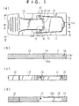
- Fig. 1 is a plan view of the structure of a pour opening unsealing device for a liquid container according to the present invention, with (a) being a plan view, (b) being a cross-sectional view taken along line A-A, (c) being a cross-sectional view taken along line B-B, and (d) being a cross-sectional view taken along line C-C.
- a pour opening unsealing device 10 which is formed of a resin material plate, comprises an unsealing portion 11, for unsealing a sealing member, such as a film-shaped sheet, that seals the pour opening of a liquid container; an actuating portion 12, for actuating (manipulating) the unsealing portion 11; and a support portion 13, for supporting the actuating portion 12 so as to secure the pour opening unsealing device in the vicinity of the pour opening of the liquid container.
- the unsealing portion 11, the actuating portion 12, and the support portion 13 are located along the same plane.
- the unsealing portion 11 and the actuating portion 13 are contiguous, being connected at the lower portion of a V-shaped portion 14, which is formed between the opposing ends of the unsealing portion 11 and the actuating portion 13, by a thin-walled portion 14a.
- the support portion 13 is so positioned that it encloses the unsealing portion 11 and a predetermined area of the contiguous actuating portion 12.
- the actuating portion 12 is supported by support bar members 15 having a predetermined length, which are provided on both sides a specified distance from the V-shaped groove 14, and is pivoted relative to the support portion 13.
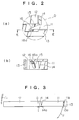
- Fig. 2(a) is an enlarged diagram showing portion D in Fig. 1(a), and Fig. 2(b) is a cross-sectional view taken along line E-E.
- one end of each support bar member 15 is coupled with the support portion 13, and the other end is inclined downward at a predetermined angle toward the actuating portion 12 and is coupled with the actuating portion 12.
- Engagement pieces 16 are formed at both sides at the end of the unsealing portion 11 nearest the actuating portion 12.
- the distal ends of the engagement pieces 16 have inclined surfaces 16a.
- the inclined surfaces 16a enable the engagement pieces 16 to smoothly move across collar portions 13b of the support portion 13 when the unsealing portion 11 is pivoted. Therefore, the inclined surfaces 16a are not always required.
- an engagement step 11a is formed at the distal end (the end away from the actuating portion 12) of the unsealing portion 11.
- An engagement step 13a is formed at a corresponding position on the support portion 13 to engage the engagement step 11a.
- the thin-walled collar portions 13b are formed on the sides of the support portion 13 that are opposite the two sides of the unsealing portion 11, as is shown in Fig. 1(d).
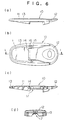
- the thus structured pour opening unsealing device 10 is so positioned and secured over the pour opening (not shown) of a liquid container 20, which is formed mainly of paper or a plastic material, as is shown in Fig. 5, that the unsealing portion 11 is located above a sealing member, such as a film-shaped sheet, that seals the pour opening.
- a sealing member such as a film-shaped sheet
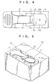
- Fig. 3 is a diagram for explaining the operation of the pour opening unsealing device 10.
- G denotes each of the support points (the centers of the connection between the support bar member 15 and the support portion 13) for the support bar members 15 at the support member 13
- H denotes each of the support points (the centers of the connection between the support bar member 15 and the actuating portion 12) for the support bar member 15 at the actuating portion 12.
- the sealing member that is disposed beneath the unsealing portion 11 for sealing the pour opening is torn off, and the pour opening is unsealed.
- the unsealing portion 11 is pivoted farther, it is rotated downward.
- the end of the unsealing portion 11 remote from the actuating portion is rotated downward, as is indicated by the arrow J.
- the sealing member that is located beneath the unsealing portion 11 for sealing the pour opening is torn, and the pour opening is unsealed.
- the unsealing portion 11 is also shifted back toward the position where it closes the opening.
- the distal end portions of the engagement pieces 16 are arrested by the collar portions 13b of the support portion 13, so that the unsealing portion 11 can not be returned to its former position and is held in this position.
- the opening K which has approximately the same shape as that of the unsealing portion 11, is maintained at the pour opening of the liquid container.
- the support bar members 15 are so located that they incline downward at a predetermined angle toward the sides of the unsealing portion 11. The need to exert excessive force to push the unsealing portion 11 is therefore effectively avoided.
- the distal end (the end farthest from the actuating portion 12) of the unsealing portion 11, is smoothly moved along the locus indicated by the arrow J.
- the disengagement of the engagement step 11a of the unsealing portion 11 from the engagement step 13a of the support portion 13 is also effected by slightly raising the end (the end farthest from the unsealing portion 11) of the actuating portion 12.
- this condition can be easily detected from the external appearance. Therefore, even if, for example, a third person uses a pour opening to introduce a noxious substance into the original contents of a liquid container that has been filled and sealed, this can be easily detected.
- the shapes and locations of the unsealing portion 11, the actuating portion 12 and the support portion 13 are not limited to those in this embodiment. Their shapes and locations may be varied so long as the unsealing portion, the actuating portion and the support portion that are formed of a resin material are located on the same plane; the unsealing portion and the actuating portion are connected at the base of a v-shaped groove, which is formed in the facing ends of these components, by a thin-walled portion; and the support portion is so positioned that it encloses the unsealing portion and a contiguous, predetermined portion of the actuating portion.
- the sealing member that covers the pour opening is not limited to the film-shaped sheet, and a plate cap that has the same shape as that of the pour opening, for example, may be used to seal the gap between its perimeter and the pour opening, or a small groove may be formed in the material at a position for a pour opening on a liquid container that can be easily perforated to provide a pour opening.
- any sealing member can be used that can be easily unsealed by the descending unsealing portion 11 and that functions to provide a good seal.
- Fig. 6 is a diagram illustrating the structure of another pour opening unsealing device for a liquid container according to the present invention, with (a) being a front view, (b) being a plan view, (c) being a cross-sectional view taken along line L-L, and (d) being a right side view.
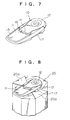
- Fig. 7 is a diagram illustrating the external appearance of the pour opening unsealing device.
- the same reference numerals as are used in Figs. 1 through 5 are also used in Figs. 6 and 7 to denote corresponding or identical components. The same applies to the other drawings.
- the above structured pour opening unsealing device 10 is attached to a pour opening (not shown) on the top of an octagonal liquid container 20, as is shown in Fig. 8.
- a pour opening (not shown) on the top of an octagonal liquid container 20, as is shown in Fig. 8.
- convex folded portions 20a of a package seal that runs across the pour opening atop the liquid container 20 fit into the groove 17.
- the pour opening unsealing device 10 can be stably attached. More specifically, since the groove 17 is formed in the bottom of the pour opening unsealing device 10, the pour opening unsealing device 10 can be attached either to a flat or to a convex package seal portion, so that when the pour opening unsealing device 10 is attached its positioning is less restricted. In other words, an available area, on the top of the liquid container 20, for forming a pour opening can be extended.
- the pour opening unsealing device 10 is so attached to the liquid container 20 that the unsealing portion 11 is located above the pour opening.
- a sealing member that is located on the lower surface of the unsealing portion 11 to seal the pour opening is torn by raising the actuating portion 12, and the pour opening is unsealed.
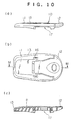
- Fig. 10 is a diagram illustrating the structure of an additional pour opening unsealing device for a liquid container according to the present invention, with (a) being a front view, (b) being a plan view, and (c) being a cross-sectional view taken along line M-M.
- Fig. 11 is a diagram illustrating the external appearance of the pour opening unsealing device.
- a difference between a pour opening unsealing device 10 shown in Figs. 10 and 11 and the pour opening unsealing device shown in Fig. 1 is that a groove 17 is formed in the bottom of the pour opening unsealing device 10.
- the other portions have the same structure and the same functions, even though their shapes differ slightly.
- Fig. 12 is a diagram showing the condition where the pour opening unsealing device 10 has been attached to the pour opening on the top of an octagonal liquid container 20. Formed atop the octagonal liquid container 20 are convex folded package seal portions 20a. The pour opening unsealing device 10 is stably attached by fitting the convex folded portions 20a into the groove 17. Since the unsealing of the pour opening is performed in the same manner as was explained while referring to Figs. 8 and 9, no explanation will be given here.
- the unsealing portion 11 that is connected to the actuating portion 12 is pivoted and tears a sealing member that is disposed on the lower side of the unsealing portion 11 and that seals the pour opening, thereby enabling the unsealing of the pour opening. Accordingly, there is no possibility of refuse being produced separately from the liquid container 20.
- the pour opening unsealing device 10 can be stably attached to the liquid container 20 as long as the convex portions are appropriately shaped and sized so that they fit into the groove 17.
- a pour opening unsealing device that is appropriate for the unsealing of a pour opening of a so-called non-resealable liquid container that once opened is not sealed again, and that is located over a sealing member, such as a film-shaped sheet, for covering and sealing the pour opening of a liquid container that is formed of packaging web made mainly of paper or plastic material.
Landscapes
- Engineering & Computer Science (AREA)
- Mechanical Engineering (AREA)
- Closures For Containers (AREA)
- Cartons (AREA)
Abstract
Description
Claims (4)
- A device (10) made of a resin material for unsealing a liquid container (20), at a position for a pour opening thereon, said device being located above said pour opening and said container being formed of packaging web made mainly of paper or plastic material, comprising:characterized in that said unsealing portion (11) and said actuating portion (12) are connected at a lower portion of a V-shaped groove (14), which is formed between facing end of said unsealing portion (11) and said actuating portion (12), by a thin-walled portion (14 a),an unsealing portion (11) for unsealing said sealing member,an actuating portion (12) for actuating said unsealing portion (11), anda support portion (13) for so supporting said actuating portion (12) that said pour opening unsealing device is secured to said liquid container (20),wherein said unsealing portion (11), said actuating portion (12) and said support portion (13) are disposed across the same plane, andwherein said support portion (13) is positioned so as to encompass said unsealing portion (11) and a predetermined portion of said actuating portion (12), which is a continuation of said unsealing portion (11),wherein said actuating portion (12) is supported by support bar members (15) having a predetermined length, which are provided on both sides a specified distance from said V-shaped groove (14), and pivots relative to said support portion (13), andwherein when the end of said actuating portion (12) that is farthest from said unsealing portion (11) is raised, the other end of said actuating portion (12) nearest said unsealing portion (11) pivots around said support bar members (15), and accordingly, said unsealing portion (11) is pivoted at said thin-walled portion (14 a) to unseal said sealing member that is located under said unsealing portion (11).
- A device according to claim 1, wherein a first engagement step (11 a) that is located at a first end of said unsealing portion (11) farthest from said actuating portion (12) engages a second engagement step (13 a) of said support portion (13), said support bar members (15) being inclined at a specified angle downward relative to said unsealing portion (11), wherein when a first end of said actuating portion (12) that is farthest from said unsealing portion (11) is raised, a second end of said actuating portion (12) nearest said unsealing portion (11) pivots at said support bar members (15), whereby said first engagement step (11 a) is disengaged from said second engagement step (13 a), and accordingly, said unsealing portion (11) is pivoted at said thin-walled portion (14 a), and wherein, as a result, said sealing member that is positioned on a lower side of said unsealing portion (11) is ripped off.
- A device according to claim 1 or 2, wherein engagement pieces (16) are formed on both sides at a second end of said unsealing portion (11) nearest said actuating portion (12), wherein when said unsealing portion (11) is pivoted downward at said thin-walled portion (14 a), said engagement pieces (16) engage collar portions (13 b) on the side portions of said support member (13), and wherein when said actuating portion (12) is returned to an original position, said engagement pieces (16) hold said unsealing portion (11) at said original position.
- A device according to any of claims 1-3, wherein a recessed portion (17) is formed in a bottom of said device, so that convex portions (20 a) at and near said pour opening of said device are fitted into said recessed portion (17).
Applications Claiming Priority (4)
| Application Number | Priority Date | Filing Date | Title |
|---|---|---|---|
| JP14549494 | 1994-06-02 | ||
| JP14549494 | 1994-06-02 | ||
| JP145494/94 | 1994-06-02 | ||
| PCT/JP1995/001060 WO1995033656A1 (en) | 1994-06-02 | 1995-05-31 | Spout seal opening device for a liquid container |
Publications (3)
| Publication Number | Publication Date |
|---|---|
| EP0760339A1 EP0760339A1 (en) | 1997-03-05 |
| EP0760339A4 EP0760339A4 (en) | 1999-09-29 |
| EP0760339B1 true EP0760339B1 (en) | 2001-04-04 |
Family
ID=15386565
Family Applications (1)
| Application Number | Title | Priority Date | Filing Date |
|---|---|---|---|
| EP95920224A Expired - Lifetime EP0760339B1 (en) | 1994-06-02 | 1995-05-31 | Spout seal opening device for a liquid container |
Country Status (11)
| Country | Link |
|---|---|
| US (1) | US5806757A (en) |
| EP (1) | EP0760339B1 (en) |
| KR (1) | KR100361061B1 (en) |
| CN (1) | CN1047992C (en) |
| AT (1) | ATE200260T1 (en) |
| DE (1) | DE69520572T2 (en) |
| DK (1) | DK0760339T3 (en) |
| ES (1) | ES2157328T3 (en) |
| PT (1) | PT760339E (en) |
| TW (1) | TW275608B (en) |
| WO (1) | WO1995033656A1 (en) |
Families Citing this family (25)
| Publication number | Priority date | Publication date | Assignee | Title |
|---|---|---|---|---|
| JP3607002B2 (en) * | 1996-04-30 | 2005-01-05 | テトラ ラバル ホールデイングス エ フイナンス ソシエテ アノニム | Container spout forming device |
| US6279769B1 (en) | 1996-04-30 | 2001-08-28 | Tetra Laval Holdings & Finance S.A. | Device for forming a mouth in a container |
| FR2751303B1 (en) * | 1996-07-19 | 1998-08-28 | Int Paper Emballages Liquides | DEVICE FOR OPENING AND CLOSING A PACKAGE, AND PACKAGE PROVIDED WITH SUCH A DEVICE |
| FR2754789B1 (en) * | 1996-10-22 | 1998-12-04 | Int Paper Emballages Liquides | DEVICE FOR OPENING AND CLOSING A PACKAGE AND PACKAGE PROVIDED WITH SUCH A DEVICE |
| WO1998033714A1 (en) * | 1997-01-30 | 1998-08-06 | Sig Combibloc Gmbh | Reclosable pouring element for applying on a flat top package |
| DE19805030C2 (en) * | 1998-02-09 | 2003-03-27 | Sig Combibloc Gmbh | Resealable pouring element and flat gable composite package provided with it |
| US6257449B1 (en) | 1998-09-11 | 2001-07-10 | J. L. Clark | Reclosable package fitment having rear intrusion and front spout lift |
| US6349866B1 (en) | 1999-02-13 | 2002-02-26 | Stone Container Corporation | Paperboard can with an integrated paperboard lid having a hinge on the lid |
| US6471122B1 (en) | 1999-02-13 | 2002-10-29 | Stone Container Corporation | Paperboard can with an integrated paperboard lid having a slide closure |
| JP2000302147A (en) * | 1999-02-16 | 2000-10-31 | Ishida Co Ltd | Container lid |
| US6682686B1 (en) | 1999-02-16 | 2004-01-27 | Ishida Co., Ltd. | Method of making a container closure |
| AU6052099A (en) * | 1999-09-22 | 2001-04-24 | J. L. Clark, Inc. | Rear intrusion front spout reclosable package fitment |
| KR200209059Y1 (en) * | 2000-07-20 | 2001-01-15 | 이한종 | Drinking can opener |
| US6354467B1 (en) * | 2001-02-12 | 2002-03-12 | International Paper Company | Device for opening and closing a package |
| US20030132230A1 (en) * | 2001-03-12 | 2003-07-17 | Bruce Gitelman | Articulated tab opener for container |
| US6575325B2 (en) * | 2001-03-12 | 2003-06-10 | Robert G. Dickie | Articulated pull tab opener for container |
| EP1461285A4 (en) * | 2001-12-06 | 2005-05-25 | Gabriel Cabelli | Hand held fluent dispensing containers |
| DE10244349A1 (en) | 2002-09-24 | 2004-04-15 | Sooth, Jürgen | Container seal with a pouring opening for a milk container is made of plastic and is inserted in and seals a cut-out in the container lid |
| WO2004028917A2 (en) * | 2002-09-24 | 2004-04-08 | Sooth Juergen | Container seal, container lid and container |
| US20040146618A1 (en) * | 2003-01-24 | 2004-07-29 | Stewart Noel G. | Perforated air-tight seal membrane for a canister containing a particulate-type product |
| US7934616B2 (en) * | 2004-02-18 | 2011-05-03 | Sig Technology Ltd. | Flip-top closure for composite and cardboard packaging |
| FR2910883A1 (en) * | 2006-12-29 | 2008-07-04 | Biomind Corp | Closing device for e.g. bottle containing soda, has cap formed by cleat that is movably mounted in opening around transversal axis for permitting tilting of cleat toward interior of cover, when tab is raised |
| WO2009144769A1 (en) * | 2008-05-30 | 2009-12-03 | Yoshihara Hiroshi | Integrally formed attachment cap with lid opened by single push |
| EA024048B1 (en) * | 2009-10-08 | 2016-08-31 | Якыджи, Месут | Liquid package cover with air duct |
| PL3424668T3 (en) * | 2017-07-05 | 2020-11-02 | Tetra Laval Holdings & Finance S.A. | A method of manufacturing an opening system for a container |
Family Cites Families (21)
| Publication number | Priority date | Publication date | Assignee | Title |
|---|---|---|---|---|
| US3301434A (en) * | 1964-12-11 | 1967-01-31 | Harvey Aluminum Inc | Can opener |
| US3952912A (en) * | 1972-03-02 | 1976-04-27 | Walter Merton Perry | Container with attached closure |
| US3967750A (en) * | 1974-09-16 | 1976-07-06 | Reynolds Metals Company | Easy-open wall |
| US3977591A (en) * | 1974-06-28 | 1976-08-31 | Ab Ziristor | Cover strip for the pouring opening in a packing container |
| US3981411A (en) * | 1976-01-26 | 1976-09-21 | Hofstetter Robert A | Safety can opener |
| US4210257A (en) * | 1979-06-21 | 1980-07-01 | American Can Company | Fracture and tear-resistant retained tab |
| JPS5931542Y2 (en) * | 1981-06-29 | 1984-09-06 | 日本製罐株式会社 | can opening device |
| JPS583436A (en) * | 1981-06-30 | 1983-01-10 | Toshiba Corp | Bus controller |
| JPS5813436A (en) * | 1981-07-17 | 1983-01-25 | Kitamura Gokin Seisakusho:Kk | Method and device for automatic molding of mold by blowing system |
| JPS5867776A (en) * | 1981-10-19 | 1983-04-22 | Sekisui Chem Co Ltd | Adhesive tape or sheet for remedy |
| JPS5867776U (en) * | 1981-10-29 | 1983-05-09 | 凸版印刷株式会社 | Container opening tool |
| JPS58145847A (en) * | 1982-02-25 | 1983-08-31 | Matsushita Electric Ind Co Ltd | Heat-pump type hot water supplying system |
| JPS58145847U (en) * | 1982-03-29 | 1983-09-30 | 岸本産業株式会社 | container lid |
| US4480763A (en) * | 1982-09-30 | 1984-11-06 | Schneider Fritz N | Beverage container opening means |
| US4553684A (en) * | 1984-11-30 | 1985-11-19 | Bennett Robert A | One piece press and lock tab for containers |
| GB2202213B (en) * | 1987-02-24 | 1990-12-05 | Profor Ab | Opening apparatus for packing containers |
| SE468805B (en) * | 1987-05-11 | 1993-03-22 | Profor Ab | OPENING DEVICE FOR PACKAGING CONTAINERS |
| US4934590A (en) * | 1989-02-27 | 1990-06-19 | Combibloc, Inc. | Package closure |
| US5147057A (en) * | 1990-10-18 | 1992-09-15 | Hoover Universal, Inc. | Inverted closures for beverage containers |
| GB2267896B (en) * | 1992-06-16 | 1996-01-17 | Tetra Pak Ltd | Reclosable containers |
| JP3202882B2 (en) * | 1994-02-25 | 2001-08-27 | 忠男 小林 | Tab |
-
1995
- 1995-05-31 US US08/750,100 patent/US5806757A/en not_active Expired - Lifetime
- 1995-05-31 PT PT95920224T patent/PT760339E/en unknown
- 1995-05-31 WO PCT/JP1995/001060 patent/WO1995033656A1/en not_active Ceased
- 1995-05-31 KR KR1019960706844A patent/KR100361061B1/en not_active Expired - Fee Related
- 1995-05-31 EP EP95920224A patent/EP0760339B1/en not_active Expired - Lifetime
- 1995-05-31 DE DE69520572T patent/DE69520572T2/en not_active Expired - Lifetime
- 1995-05-31 ES ES95920224T patent/ES2157328T3/en not_active Expired - Lifetime
- 1995-05-31 AT AT95920224T patent/ATE200260T1/en not_active IP Right Cessation
- 1995-05-31 CN CN95193725A patent/CN1047992C/en not_active Expired - Fee Related
- 1995-05-31 DK DK95920224T patent/DK0760339T3/en active
- 1995-08-02 TW TW084108043A patent/TW275608B/zh active
Also Published As
| Publication number | Publication date |
|---|---|
| WO1995033656A1 (en) | 1995-12-14 |
| EP0760339A4 (en) | 1999-09-29 |
| DE69520572T2 (en) | 2001-07-12 |
| ATE200260T1 (en) | 2001-04-15 |
| DE69520572D1 (en) | 2001-05-10 |
| ES2157328T3 (en) | 2001-08-16 |
| TW275608B (en) | 1996-05-11 |
| KR100361061B1 (en) | 2003-02-19 |
| CN1151141A (en) | 1997-06-04 |
| US5806757A (en) | 1998-09-15 |
| PT760339E (en) | 2001-09-28 |
| DK0760339T3 (en) | 2001-08-06 |
| EP0760339A1 (en) | 1997-03-05 |
| CN1047992C (en) | 2000-01-05 |
Similar Documents
| Publication | Publication Date | Title |
|---|---|---|
| US5806757A (en) | Device for unsealing pour opening of liquid container | |
| US5197624A (en) | Cup lid | |
| US5062542A (en) | Easy-open and reclosable container | |
| RU2183183C2 (en) | Integral closure | |
| RU2126348C1 (en) | Opener | |
| US20070164026A1 (en) | Automatic opening, venting, and closing re-sealable container closure | |
| EP1112943A1 (en) | Container with cap | |
| KR100523090B1 (en) | Reclosable pouring element and a flat gable composite packaging provided therewith | |
| CN101267993A (en) | Container Closure | |
| JP3312761B2 (en) | Opening device and manufacturing method thereof | |
| JPS6181949A (en) | Simple open-close vessel | |
| CA2427582C (en) | Opening device | |
| CA2251787A1 (en) | An opening arrangement for packaging containers | |
| US7225947B2 (en) | Pouring spout seal for composite packagings | |
| US6536627B1 (en) | Reclosable pourer spout for a container | |
| US5035343A (en) | Easy-open and reclosable container | |
| GB2267896A (en) | Reclosable containers | |
| EP0999144B1 (en) | Container of gabled roof type having top seal rib and top sealing device therefor | |
| EP0645315B1 (en) | Easy-open/reclosure device for flat top carton having deformable pour spout | |
| US5755359A (en) | Opening device for a liquid package | |
| JP2629023B2 (en) | Dispenser for paper containers | |
| EP0793602B1 (en) | Pull-tab for a liquid container | |
| JP3652407B2 (en) | Liquid container container opening device | |
| EP0015271A1 (en) | Reclosable container | |
| JP2593374Y2 (en) | Packaging containers |
Legal Events
| Date | Code | Title | Description |
|---|---|---|---|
| PUAI | Public reference made under article 153(3) epc to a published international application that has entered the european phase |
Free format text: ORIGINAL CODE: 0009012 |
|
| 17P | Request for examination filed |
Effective date: 19961225 |
|
| AK | Designated contracting states |
Kind code of ref document: A1 Designated state(s): AT BE CH DE DK ES FR GB GR IE IT LI LU NL PT SE |
|
| RIN1 | Information on inventor provided before grant (corrected) |
Inventor name: HYLTA, PATRICK Inventor name: MOCK, ELMAR Inventor name: OHLSSON, PER |
|
| A4 | Supplementary search report drawn up and despatched |
Effective date: 19990818 |
|
| AK | Designated contracting states |
Kind code of ref document: A4 Designated state(s): AT BE CH DE DK ES FR GB GR IE IT LI LU NL PT SE |
|
| 17Q | First examination report despatched |
Effective date: 20000216 |
|
| GRAG | Despatch of communication of intention to grant |
Free format text: ORIGINAL CODE: EPIDOS AGRA |
|
| GRAG | Despatch of communication of intention to grant |
Free format text: ORIGINAL CODE: EPIDOS AGRA |
|
| GRAH | Despatch of communication of intention to grant a patent |
Free format text: ORIGINAL CODE: EPIDOS IGRA |
|
| GRAH | Despatch of communication of intention to grant a patent |
Free format text: ORIGINAL CODE: EPIDOS IGRA |
|
| GRAA | (expected) grant |
Free format text: ORIGINAL CODE: 0009210 |
|
| ITF | It: translation for a ep patent filed | ||
| AK | Designated contracting states |
Kind code of ref document: B1 Designated state(s): AT BE CH DE DK ES FR GB GR IE IT LI LU NL PT SE |
|
| PG25 | Lapsed in a contracting state [announced via postgrant information from national office to epo] |
Ref country code: BE Free format text: LAPSE BECAUSE OF FAILURE TO SUBMIT A TRANSLATION OF THE DESCRIPTION OR TO PAY THE FEE WITHIN THE PRESCRIBED TIME-LIMIT Effective date: 20010404 |
|
| REF | Corresponds to: |
Ref document number: 200260 Country of ref document: AT Date of ref document: 20010415 Kind code of ref document: T |
|
| REG | Reference to a national code |
Ref country code: CH Ref legal event code: NV Representative=s name: A. BRAUN, BRAUN, HERITIER, ESCHMANN AG PATENTANWAE Ref country code: CH Ref legal event code: EP |
|
| REG | Reference to a national code |
Ref country code: IE Ref legal event code: FG4D |
|
| REF | Corresponds to: |
Ref document number: 69520572 Country of ref document: DE Date of ref document: 20010510 |
|
| PG25 | Lapsed in a contracting state [announced via postgrant information from national office to epo] |
Ref country code: LU Free format text: LAPSE BECAUSE OF NON-PAYMENT OF DUE FEES Effective date: 20010531 Ref country code: IE Free format text: LAPSE BECAUSE OF NON-PAYMENT OF DUE FEES Effective date: 20010531 |
|
| ET | Fr: translation filed | ||
| PG25 | Lapsed in a contracting state [announced via postgrant information from national office to epo] |
Ref country code: GR Free format text: LAPSE BECAUSE OF FAILURE TO SUBMIT A TRANSLATION OF THE DESCRIPTION OR TO PAY THE FEE WITHIN THE PRESCRIBED TIME-LIMIT Effective date: 20010706 |
|
| REG | Reference to a national code |
Ref country code: DK Ref legal event code: T3 |
|
| REG | Reference to a national code |
Ref country code: ES Ref legal event code: FG2A Ref document number: 2157328 Country of ref document: ES Kind code of ref document: T3 |
|
| REG | Reference to a national code |
Ref country code: PT Ref legal event code: SC4A Free format text: AVAILABILITY OF NATIONAL TRANSLATION Effective date: 20010619 |
|
| REG | Reference to a national code |
Ref country code: GB Ref legal event code: IF02 |
|
| PLBE | No opposition filed within time limit |
Free format text: ORIGINAL CODE: 0009261 |
|
| STAA | Information on the status of an ep patent application or granted ep patent |
Free format text: STATUS: NO OPPOSITION FILED WITHIN TIME LIMIT |
|
| REG | Reference to a national code |
Ref country code: IE Ref legal event code: MM4A |
|
| 26N | No opposition filed | ||
| PGFP | Annual fee paid to national office [announced via postgrant information from national office to epo] |
Ref country code: NL Payment date: 20050429 Year of fee payment: 11 |
|
| PGFP | Annual fee paid to national office [announced via postgrant information from national office to epo] |
Ref country code: PT Payment date: 20050505 Year of fee payment: 11 |
|
| PGFP | Annual fee paid to national office [announced via postgrant information from national office to epo] |
Ref country code: DK Payment date: 20050524 Year of fee payment: 11 |
|
| PG25 | Lapsed in a contracting state [announced via postgrant information from national office to epo] |
Ref country code: DK Free format text: LAPSE BECAUSE OF NON-PAYMENT OF DUE FEES Effective date: 20060531 |
|
| PG25 | Lapsed in a contracting state [announced via postgrant information from national office to epo] |
Ref country code: PT Free format text: LAPSE BECAUSE OF NON-PAYMENT OF DUE FEES Effective date: 20061130 |
|
| PG25 | Lapsed in a contracting state [announced via postgrant information from national office to epo] |
Ref country code: NL Free format text: LAPSE BECAUSE OF NON-PAYMENT OF DUE FEES Effective date: 20061201 |
|
| REG | Reference to a national code |
Ref country code: DK Ref legal event code: EBP |
|
| REG | Reference to a national code |
Ref country code: PT Ref legal event code: MM4A Free format text: LAPSE DUE TO NON-PAYMENT OF FEES Effective date: 20061130 |
|
| NLV4 | Nl: lapsed or anulled due to non-payment of the annual fee |
Effective date: 20061201 |
|
| PGFP | Annual fee paid to national office [announced via postgrant information from national office to epo] |
Ref country code: AT Payment date: 20070502 Year of fee payment: 13 |
|
| PGFP | Annual fee paid to national office [announced via postgrant information from national office to epo] |
Ref country code: SE Payment date: 20070529 Year of fee payment: 13 |
|
| PGFP | Annual fee paid to national office [announced via postgrant information from national office to epo] |
Ref country code: CH Payment date: 20070530 Year of fee payment: 13 |
|
| REG | Reference to a national code |
Ref country code: CH Ref legal event code: PFA Owner name: TETRA LAVAL HOLDINGS & FINANCE SA Free format text: TETRA LAVAL HOLDINGS & FINANCE SA#70, AVENUE GENERAL-GUISAN, P.O. BOX 430#1009 PULLY (CH) -TRANSFER TO- TETRA LAVAL HOLDINGS & FINANCE SA#70, AVENUE GENERAL-GUISAN, P.O. BOX 430#1009 PULLY (CH) |
|
| REG | Reference to a national code |
Ref country code: CH Ref legal event code: PL |
|
| PG25 | Lapsed in a contracting state [announced via postgrant information from national office to epo] |
Ref country code: LI Free format text: LAPSE BECAUSE OF NON-PAYMENT OF DUE FEES Effective date: 20080531 Ref country code: CH Free format text: LAPSE BECAUSE OF NON-PAYMENT OF DUE FEES Effective date: 20080531 |
|
| EUG | Se: european patent has lapsed | ||
| PG25 | Lapsed in a contracting state [announced via postgrant information from national office to epo] |
Ref country code: AT Free format text: LAPSE BECAUSE OF NON-PAYMENT OF DUE FEES Effective date: 20080531 |
|
| PGFP | Annual fee paid to national office [announced via postgrant information from national office to epo] |
Ref country code: IT Payment date: 20090528 Year of fee payment: 15 |
|
| PG25 | Lapsed in a contracting state [announced via postgrant information from national office to epo] |
Ref country code: SE Free format text: LAPSE BECAUSE OF NON-PAYMENT OF DUE FEES Effective date: 20080601 |
|
| PG25 | Lapsed in a contracting state [announced via postgrant information from national office to epo] |
Ref country code: IT Free format text: LAPSE BECAUSE OF NON-PAYMENT OF DUE FEES Effective date: 20100531 |
|
| PGFP | Annual fee paid to national office [announced via postgrant information from national office to epo] |
Ref country code: DE Payment date: 20120523 Year of fee payment: 18 |
|
| PGFP | Annual fee paid to national office [announced via postgrant information from national office to epo] |
Ref country code: FR Payment date: 20120608 Year of fee payment: 18 Ref country code: GB Payment date: 20120530 Year of fee payment: 18 |
|
| PGFP | Annual fee paid to national office [announced via postgrant information from national office to epo] |
Ref country code: ES Payment date: 20120607 Year of fee payment: 18 |
|
| GBPC | Gb: european patent ceased through non-payment of renewal fee |
Effective date: 20130531 |
|
| PG25 | Lapsed in a contracting state [announced via postgrant information from national office to epo] |
Ref country code: DE Free format text: LAPSE BECAUSE OF NON-PAYMENT OF DUE FEES Effective date: 20131203 |
|
| REG | Reference to a national code |
Ref country code: DE Ref legal event code: R119 Ref document number: 69520572 Country of ref document: DE Effective date: 20131203 |
|
| REG | Reference to a national code |
Ref country code: FR Ref legal event code: ST Effective date: 20140131 |
|
| PG25 | Lapsed in a contracting state [announced via postgrant information from national office to epo] |
Ref country code: GB Free format text: LAPSE BECAUSE OF NON-PAYMENT OF DUE FEES Effective date: 20130531 |
|
| PG25 | Lapsed in a contracting state [announced via postgrant information from national office to epo] |
Ref country code: FR Free format text: LAPSE BECAUSE OF NON-PAYMENT OF DUE FEES Effective date: 20130531 |
|
| REG | Reference to a national code |
Ref country code: ES Ref legal event code: FD2A Effective date: 20140610 |
|
| PG25 | Lapsed in a contracting state [announced via postgrant information from national office to epo] |
Ref country code: ES Free format text: LAPSE BECAUSE OF NON-PAYMENT OF DUE FEES Effective date: 20130601 |