EP0759623A1 - Storage installation for nuclear fuel assemblies and storage rack therefor - Google Patents
Storage installation for nuclear fuel assemblies and storage rack therefor Download PDFInfo
- Publication number
- EP0759623A1 EP0759623A1 EP96810541A EP96810541A EP0759623A1 EP 0759623 A1 EP0759623 A1 EP 0759623A1 EP 96810541 A EP96810541 A EP 96810541A EP 96810541 A EP96810541 A EP 96810541A EP 0759623 A1 EP0759623 A1 EP 0759623A1
- Authority
- EP
- European Patent Office
- Prior art keywords
- storage rack
- supported
- bearing arrangement
- fuel elements
- support structure
- Prior art date
- Legal status (The legal status is an assumption and is not a legal conclusion. Google has not performed a legal analysis and makes no representation as to the accuracy of the status listed.)
- Granted
Links
Images


Classifications
-
- G—PHYSICS
- G21—NUCLEAR PHYSICS; NUCLEAR ENGINEERING
- G21C—NUCLEAR REACTORS
- G21C19/00—Arrangements for treating, for handling, or for facilitating the handling of, fuel or other materials which are used within the reactor, e.g. within its pressure vessel
- G21C19/02—Details of handling arrangements
- G21C19/06—Magazines for holding fuel elements or control elements
- G21C19/07—Storage racks; Storage pools
-
- Y—GENERAL TAGGING OF NEW TECHNOLOGICAL DEVELOPMENTS; GENERAL TAGGING OF CROSS-SECTIONAL TECHNOLOGIES SPANNING OVER SEVERAL SECTIONS OF THE IPC; TECHNICAL SUBJECTS COVERED BY FORMER USPC CROSS-REFERENCE ART COLLECTIONS [XRACs] AND DIGESTS
- Y02—TECHNOLOGIES OR APPLICATIONS FOR MITIGATION OR ADAPTATION AGAINST CLIMATE CHANGE
- Y02E—REDUCTION OF GREENHOUSE GAS [GHG] EMISSIONS, RELATED TO ENERGY GENERATION, TRANSMISSION OR DISTRIBUTION
- Y02E30/00—Energy generation of nuclear origin
- Y02E30/30—Nuclear fission reactors
Definitions
- the invention relates to a bearing arrangement for storing nuclear fuel elements according to the preamble of claim 1 and a storage rack for such an arrangement.
- the vertical channels intended for receiving the fuel elements are formed by overlapping, intersecting metal strips.
- the sheet metal strips are arranged between a support structure in the form of a lower grid plate and an upper grid plate, which grid plates each have openings for inserting or locking the fuel elements.
- the fuel assemblies are supported on the lower grid plate, which is thus loaded by the weight of the channels and additionally by the weight of the fuel assemblies.
- the known bearing arrangement therefore requires a relatively complex, heavy-duty construction of the lower grid plate.
- the invention has for its object to provide a particularly improved bearing arrangement in this regard and a storage rack that can be produced with little labor and cost in a simplified, lightweight design compared to the previous embodiment, which at the same time enables an embodiment with load-bearing parts that are significantly less stressed than previous versions .
- An essential advantage of the bearing arrangement according to the invention is that the fuel elements differ from one another and from the nature, e.g. independent of any deformation of the support structure in the channels and can be placed on the floor without additional load on the storage rack.
- Another advantage of the bearing arrangement according to the invention is that it allows the use of a much lighter storage rack than in previous designs.
- the embodiment according to claim 2 allows any, possibly different height settings of the fuel elements to be supported on support pieces.
- the support pieces with stop parts formed on them can each be held at a distance from the support structure, which permits correspondingly limited vertical relative movements of the support pieces and the support structure, for example in the event of an earthquake.
- the embodiment according to claim 4 allows in a simple manner an increase in the storage rack and thus a corresponding increase, possibly a doubling, of the storage capacity.
- the fuel elements arranged in the second height position can also be supported on the floor via the fuel elements already located in the lower storage rack without additional load on the supporting structure of the lower storage rack.
- the upper fuel assemblies can be stored at any height from the lower fuel assemblies via spacers, which, according to claim 7, can be vertically supported relative to the storage rack on the lower fuel assemblies or, according to claim 8, can be fixed in the storage rack.
- the intermediate pieces can be arranged loosely or, according to claim 9, can each be connected to one of the fuel assemblies.
- the upper storage rack can be designed with a height that corresponds to only a fraction of the length of the upper fuel elements to be stored, so that the overall height of the two storage racks can be significantly less than twice the length of the fuel elements to be stored.
- a storage rack for the bearing arrangement according to the invention is the subject of claim 11.
- This embodiment permits precise centering and guiding of the support pieces which take up the weight of the fuel elements, of which a part number is at the same time as Supports for the support structure and thus for the entire storage rack can be used.
- the embodiment according to claim 13 allows an accurate positioning and leveling of the support structure in a predetermined, e.g. the circulation of the coolant favoring high altitude.
- the 1 contains a storage rack 1 which can be inserted into a storage pool and has a lower support structure 2, an upper support structure 3 and a plurality of vertical channels 4, which are arranged next to one another, for receiving nuclear fuel elements 5.
- the support and support structures 2 and 3, which can be implemented arbitrarily are in the drawing is shown in simplified form in the form of a base plate or a cover plate.
- the channels 4 are delimited by walls 6, which are formed by cross-arranged sheets made of a neutron-absorbing material, for example a boron alloy.
- the walls 6 can be formed from sheet metal parts running over the entire height of the storage rack 1 or, as is known, for example, from the aforementioned DE-OS 29 30 237, from sheet metal strips which can be placed one above the other and can be placed on top of one another.
- the support structure 2 can, as shown, be supported on the base parts of the storage basin (not shown) by foot parts 7 attached to it.
- the storage pool which can contain a plurality of storage racks 1 arranged next to one another, extends beyond the height of the storage rack 1 and is filled with a coolant, for example water, which also serves as a shield against radiation from the fuel elements.
- the fuel assemblies 5 are each arranged with a lateral play in openings 8 and 9 of the support and holding structures 2 and 3 and at a distance from the lower support structure 2, independently of this, each with a foot section 11 directly on the floor supported of the storage pool and guided vertically movable with a head part 12 in the upper holding structure 3.
- FIG. 2 essentially corresponds to that according to FIG. 1, with the difference that the fuel elements 5 with their base parts 11 are each supported on the floor of the storage pool via a support piece 14.
- the support pieces 14 are shown vertically movable in the support structure 2 and each have a head part projecting above the support structure 2, on which a stop part 23 is formed, which can be positioned at a distance A from the support structure 2.
- an upper bearing frame 1 a can be placed on the upper holding structure 3 of the bearing frame 1, which has a corresponding lower supporting structure 2a and an upper holding structure 3a and with channels 4a aligned with the channels 4 of the bearing frame 1 for receiving fuel elements 5a to be stored at a second altitude.
- the upper fuel assemblies 5a are supported with their foot sections 11 directly on the head sections 12 of the lower fuel assemblies 5, which can be provided with positioning parts for the foot sections 11. Accordingly, the weight of the upper fuel assemblies 5a can also be transferred to the floor of the storage pool 1 via the fuel assemblies 5 without additional loading of the storage rack 1.
- the upper fuel assemblies 5a are supported on the lower fuel assemblies 5 via intermediate pieces 16, each of which is designed in the form of a spacer arranged vertically movably in the corresponding channel 4a relative to the support structure 2a of the upper storage rack la, and on the upwardly projecting ones Head parts 12 of the fuel assemblies 5 are placed.
- the weight of the fuel assemblies 5a is transferred via the intermediate pieces 16 to the lower fuel assemblies 5 and via these directly to the bottom of the storage pool.
- the intermediate pieces 16 can, as shown, be designed with passage openings 15, which are the circulation of the coolant ensure within channels 4 and 4a.
- the intermediate pieces 16 can also be designed as positioning parts which are fixed or detachably connected to the fuel elements 5 or 5.
- the upper storage rack la is also designed with a height H1 which is smaller than the height H of the lower storage rack 1 and which therefore corresponds to only a fraction of the length of the fuel elements 5a.
- the upper fuel elements 5a are each arranged in a casing 19 made of a neutron-absorbing material surrounding them.
- the sleeves 19 are each firmly connected to the fuel assembly 5a concerned and shaped in such a way that they each form an installation unit which can be inserted into one of the upper channels 4a in the vertical direction with the fuel assemblies 5a.
- the walls 6a of the channels 4a can be made of a weldable material and can essentially be designed as a guide arrangement for the installation units formed by the fuel elements 5a and the sleeves 19.
- a support piece 14 according to FIG. 2 can also be provided between the lower fuel assemblies 5 and the bottom in these embodiments as well.
- intermediate pieces 16 can be provided between the lower and upper fuel elements 5 and 5a.
- the intermediate pieces 16 can be designed as supporting parts, via which the upper fuel elements 5a are supported on the support structure 2a of the upper storage frame 1 a, so that the weight of the upper one Fuel assemblies 5a, regardless of the lower fuel assemblies 5, are transferred via the channel walls 6 to the support structure 2 of the lower storage rack 1, which is relieved of the weight of the lower fuel assemblies 5.
- the support structure 2 is only stressed by supporting forces introduced via the channel walls 6, and thus appropriately cheap.
- the support structure 2 can therefore, although partially loaded by the weight of the upper fuel elements 5a, also be designed in a correspondingly light manner.
- the upper fuel elements 5a can also be supported directly on the support structure 2a of the upper storage rack la.
- An embodiment is also possible in which the upper fuel assemblies 5a are supported - directly or via corresponding intermediate pieces 16 - on the upper holding structure 3 of the lower storage rack 1, as a result of which the supporting structure 2a of the upper storage rack la is designed in a correspondingly light, simple construction can
- the support structure 2 is designed as a grating 17 which connects the lower end sections 6 'of the channel walls 6 and divides the channels 4 and which can be formed by metal sheets made of a weldable material.
- the end sections 6 ' can also be formed by sheets made of weldable material, which are aligned with the sheets made of neutron-absorbing material and connected to the grating 17 to form a dimensionally stable support structure for the channels 4.
- the holding structure 3 shown in the form of a plate in FIG. 5 can also be formed by the upper end sections of the channel walls 6.
- the grating 17 contains at least a part of the channels 4 at least one guide arrangement 18 for one of the vertically movable support pieces 14 or forms such a guide arrangement.
- the guide arrangements 18 can be formed by guide bushes or, as shown in FIG. 8, each by two pairs of cross-standing support plates 20 of the grating 17 which extend over a plurality of channels 4 and which together and with the plates form the end section 6 'or can be welded to the support structure 2. Most of the support pieces 14 are guided in the guide arrangements 18 so as to be freely displaceable in the vertical direction. A number of the intermediate pieces, shown as intermediate pieces 14 'distributed over the cross section of the storage rack 1, are coupled to the grating 17 via suspension means 22, by means of which the lower support structure 2 and thus the entire storage rack 1 are supported on these suspension pieces 14'.
- Threaded bushings fastened in the grating 17 as shown in the illustration can be provided as support means 22, in which the support pieces 14 ′, each provided with a corresponding thread, are guided in a height-adjustable and lockable manner.
- the intermediate pieces 14 and 14 ' can be designed with stop parts 23, which can be adjusted above the grating 17 at a distance A or B, respectively, which have corresponding vertical relative movements between the grating 17 and the intermediate pieces 14 ensures and prevents the weight of the fuel elements 5 supported on the intermediate pieces 14 from being transferred to the grating 17.
- the distances A are selected so that they have a small, predefinable movement of the storage rack 1, e.g. in the event of an earthquake, allow without loading the storage rack 1 by the weight of the fuel elements. In the event of a seismic load, stabilization of the storage rack 1 can also be achieved, since the shoulder-like stop parts 23 of the intermediate pieces 14 loaded by the fuel elements 5 limit the vertical movements of the grating 17 to a dimension corresponding to the distance A and thus a tilting movement of the storage rack 1 or Counteract storage racks 1 and 1 a.
- the distances B are used to adjust the height and to level the support structure 2, regardless of the nature of the floor of the storage pool.
- a storage rack 1 arranged in a storage pool contains a plurality of vertical channels 4 for receiving fuel elements 5.
- the channels 4, the walls 6 of which are formed by sheets of a neutron-absorbing material, are supported on a base of the storage pool that is relieved of the weight of the fuel elements 5
- Support structure 2 arranged.
- the fuel elements 5 are each supported at a distance from the support structure 2 on the bottom of the water basin. Accordingly, the storage rack 1 can be designed in an advantageously lightweight construction. At the same time, an optimal, even distribution of the building loads on the floor of the storage pool is achieved. Due to the relief of the support structure 2 from the weight of the fuel elements 5 and the uniform load distribution on the floor of the storage pool, favorable conditions for the construction of a second, upper one Layer of fuel elements to be stored created, whereby the storage capacity can be increased significantly.
Abstract
Description
Die Erfindung betrifft eine Lageranordnung zum Lagern nuklearer Brennelemente entsprechend dem Oberbegriff des Patentanspruchs 1 sowie ein Lagergestell für eine derartige Anordnung.The invention relates to a bearing arrangement for storing nuclear fuel elements according to the preamble of
Bei einer aus der DE-OS 29 30 237 bekannten Lageranordnung der genannten Art sind die zur Aufnahme der Brennelemente bestimmten vertikalen Kanäle durch übereinanderstehend angeordnete, sich kreuzende Blechstreifen gebildet. Die Blechstreifen sind zwischen einer Stützkonstruktion in Form einer unteren Gitterplatte und einer oberen Gitterplatte angeordnet, welche Gitterplatten je Oeffnungen zum Einführen bzw. Arretieren der Brennelemente aufweisen. Bei der bekannten Lageranordnung sind die Brennelemente auf der unteren Gitterplatte abgestützt, welche somit durch das Gewicht der Kanäle, und zusätzlich durch das Gewicht der Brennelemente belastet wird. Die bekannte Lageranordnung erfordert daher eine relativ aufwendige, hoch belastbare Konstruktion der unteren Gitterplatte.In a bearing arrangement of the type mentioned known from DE-OS 29 30 237, the vertical channels intended for receiving the fuel elements are formed by overlapping, intersecting metal strips. The sheet metal strips are arranged between a support structure in the form of a lower grid plate and an upper grid plate, which grid plates each have openings for inserting or locking the fuel elements. In the known bearing arrangement, the fuel assemblies are supported on the lower grid plate, which is thus loaded by the weight of the channels and additionally by the weight of the fuel assemblies. The known bearing arrangement therefore requires a relatively complex, heavy-duty construction of the lower grid plate.
Der Erfindung liegt die Aufgabe zugrunde, eine insbesondere in dieser Hinsicht verbesserte Lageranordnung sowie ein mit geringem Arbeits- und Kostenaufwand herstellbares Lagergestell in einer gegenüber bisherigen Ausführung vereinfachten, leichten Bauweise zu schaffen, welche zugleich eine Ausführung mit gegenüber bisherigen Ausführungen wesentlich geringer beanspruchten tragenden Teilen ermöglicht.The invention has for its object to provide a particularly improved bearing arrangement in this regard and a storage rack that can be produced with little labor and cost in a simplified, lightweight design compared to the previous embodiment, which at the same time enables an embodiment with load-bearing parts that are significantly less stressed than previous versions .
Diese Aufgabe wird erfindungsgemäss durch die kennzeichnenden Merkmale des Patentanspruchs 1 gelöst.According to the invention, this object is achieved by the characterizing features of
Ein wesentlicher Vorteil der erfindungsgemässen Lageranordnung besteht darin, dass die Brennelemente voneinander und von der Beschaffenheit, z.B. von allfälligen Verformungen der Stützkonstruktion unabhängig in die Kanäle eingeführt und ohne zusätzliche Belastung des Lagergestells auf den Boden abgesetzt werden können. Ein weiterer Vorteil der erfindungsgemässen Lageranordnung besteht darin, dass sie die Verwendung eines wesentlich leichteren Lagergestells als bei bisherigen Ausführungen gestattet.An essential advantage of the bearing arrangement according to the invention is that the fuel elements differ from one another and from the nature, e.g. independent of any deformation of the support structure in the channels and can be placed on the floor without additional load on the storage rack. Another advantage of the bearing arrangement according to the invention is that it allows the use of a much lighter storage rack than in previous designs.
Ausgestaltungen des Erfindungsgegenstandes sind in den abhängigen Ansprüchen angegeben.Embodiments of the subject matter of the invention are specified in the dependent claims.
Die Ausführung nach Anspruch 2 gestattet beliebige, gegebenenfalls unterschiedliche Höheneinstellungen der auf Tragstücken zu lagernden Brennelemente.The embodiment according to
Gemäss Anspruch 3 können die Tragstücke mit an ihnen ausgebildeten Anschlagpartien je in einem Abstand von der Stützkonstruktion gehalten werden, der entsprechend begrenzte vertikale Relativbewegungen der Tragstücke und der Stützkonstruktion, z.B. im Falle eines Erdbebens zulässt.According to
Die Ausführung nach Anspruch 4 gestattet auf einfache Weise eine Aufstockung des Lagergestells und damit eine entsprechende Vergrösserung, gegebenenfalls eine Verdoppelung, der Lagerkapazität.The embodiment according to
Gemäss Anspruch 5 können auch die in der zweiten Höhenlage angeordneten Brennelemente - über die bereits im unteren Lagergestell befindlichen Brennelemente - ohne zusätzliche Belastung der Stützkonstruktion des unteren Lagergestells auf dem Boden abgestützt werden.According to
Gemäss Anspruch 6 können auch die oberen Brennelemente in beliebigen Höhenabständen von den unteren Brennelementen über Zwischenstücke gelagert werden, welche gemäss Anspruch 7 relativ zum Lagergestell vertikal beweglich auf den unteren Brennelementen abgestützt oder,gemäss Anspruch 8, im Lagergestell feststehend angeordnet sein können.According to
Die Zwischenstücke können lose angeordnet oder, gemäss Anspruch 9, je mit einem der Brennelemente verbunden sein.The intermediate pieces can be arranged loosely or, according to
Gemäss Anspruch 10 kann das obere Lagergestell mit einer Bauhöhe ausgeführt werden, die nur einem Bruchteil der Länge der zu lagernden oberen Brennelemente entspricht, so dass die gesamte Bauhöhe der beiden Lagergestelle wesentlich kleiner sein kann als die doppelte Länge der zu lagernden Brennelemente.According to
Ein Lagergestell für die erfindungsgemässe Lageranordnung ist Gegenstand des Anspruchs 11. Diese Ausführung gestattet eine genaue Zentrierung und Führung der das Gewicht der Brennelemente aufnehmenden Tragstücke, von denen gemäss Anspruch 12 eine Teilzahl zugleich als Abstützungen für die Stützkonstruktion und damit für das gesamte Lagergestell verwendbar sind.A storage rack for the bearing arrangement according to the invention is the subject of
Die Ausführung nach Anspruch 13 gestattet eine von der Beschaffenheit des Bodens des Lagerbeckens unabhängige, genaue Positionierung und Nivellierung der Stützkonstruktion in einer vorbestimmten, z.B. die Zirkulation des Kühlmittels begünstigenden Höhenlage.The embodiment according to claim 13 allows an accurate positioning and leveling of the support structure in a predetermined, e.g. the circulation of the coolant favoring high altitude.
Die Erfindung wird anhand von in der Zeichnung schematisch dargestellten Ausführungsbeispielen erläutert. Es zeigen:The invention is explained on the basis of exemplary embodiments shown schematically in the drawing. Show it:
- Fig. 1 bis 51 to 5
- Teil-Längsschnitte von erfindungsgemäss ausgebildeten Lageranordnungen für nukleare Brennelemente, je nach einer anderen Ausführungsform,Partial longitudinal sections of bearing arrangements designed according to the invention for nuclear fuel elements, depending on another embodiment,
- Fig. 4aFig. 4a
- eine Einzelheit einer Lageranordnung gemäss Fig.4, nach einer weiteren Ausführungsform,a detail of a bearing arrangement according to Figure 4, according to another embodiment,
- Fig. 6 und 76 and 7
- je eine Einzelheit VI bzw. VII der Lageranordnung nach Fig. 5, in einer grösseren Darstellung,5 a detail VI or VII of the bearing arrangement according to FIG. 5, in a larger representation,
- Fig. 8Fig. 8
- einen Horizontalschnitt der Lageranordnung nach der Linie VIII-VIII in Fig. 5.a horizontal section of the bearing arrangement along the line VIII-VIII in Fig. 5th
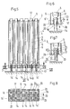
Die Lageranordnung nach Fig. 1 enthält ein in ein Lagerbecken einsetzbares Lagergestell 1 mit einer unteren Stützkonstruktion 2, einer oberen Haltekonstruktion 3 und mehreren, zwischen diesen nebeneinander angeordneten vertikalen Kanälen 4 zur Aufnahme von nuklearen Brennelementen 5. Die Stütz- und Haltekonstruktionen 2 und 3, welche beliebig ausgeführt sein können, sind in der Zeichnung vereinfacht je in Form einer Grundplatte bzw. einer Deckplatte dargestellt. Die Kanäle 4 sind durch Wände 6 begrenzt, die durch kreuzweise angeordnete Bleche aus einem neutronenabsorbierenden Werkstoff, z.B. einer Borlegierung, gebildet sind. Die Wände 6 können aus über die ganze Höhe des Lagergestells 1 verlaufenden Blechteilen oder, wie z.B. aus der eingangs genannten DE-OS 29 30 237 bekannt, aus übereinander angeordneten, aufeinander aufsetzbaren Blechstreifen gebildet sein. Die Stützkonstruktion 2 kann darstellungsgemäss über an ihr angebrachte Fussteile 7 auf dem Boden des nicht weiter dargestellten Lagerbeckens abgestützt sein. Das Lagerbecken, welches mehrere, nebeneinander angeordnete Lagergestelle 1 enthalten kann, erstreckt sich über die Höhe des Lagergestells 1 hinaus und ist mit einem Kühlmittel, z.B. Wasser, gefüllt, das zugleich als Abschirmung gegen Strahlung der Brennelemente dient. Bei der dargestellten Ausführung sind die Brennelemente 5 je mit einem seitlichen Spiel in Oeffnungen 8 und 9 der Stütz- und Haltekonstruktionen 2 bzw. 3 angeordnet und im Abstand von der unteren Stützkonstruktion 2, von dieser unabhängig, je mit einer Fusspartie 11 unmittelbar auf dem Boden des Lagerbeckens abgestützt und mit einer Kopfpartie 12 in der oberen Haltekonstruktion 3 vertikal beweglich geführt. Die entsprechend vom Gewicht der Brennelemente 5 entlastete Stützkonstruktion 2 braucht somit lediglich als Traganordnung für das Lagergestell dimensioniert zu werden und kann in einer entsprechend leichten Bauweise ausgeführt werden.1 contains a
In den Zeichnungsfiguren sind aneinander entsprechende Teile mit gleichen Bezugszeichen versehen. Die Ausführung nach Fig. 2 entspricht im wesentlichen derjenigen nach Fig. 1, mit dem Unterschied, dass die Brennelemente 5 mit ihren Fusspartien 11 je über ein Tragstück 14 auf dem Boden des Lagerbeckens abgestützt sind. Die Tragstücke 14 sind darstellungsgemäss in der Stützkonstruktion 2 vertikal beweglich angeordnet und je mit einem über die Stützkonstruktion 2 vorstehenden Kopfteil ausgeführt, an dem eine Anschlagpartie 23 ausgebildet ist, die in einem Abstand A von der Stützkonstruktion 2 positionierbar ist.In the drawing figures, parts which correspond to one another are provided with the same reference symbols. The embodiment according to FIG. 2 essentially corresponds to that according to FIG. 1, with the difference that the
Entsprechend der Darstellung nach Fig. 3 kann auf der oberen Haltekonstruktion 3 des Lagergestells 1 ein oberes Lagergestell la aufgesetzt sein, welches eine entsprechende untere Stützkonstruktion 2a und eine obere Haltekonstruktion 3a aufweist und mit zu den Kanälen 4 des Lagergestells 1 fluchtenden Kanälen 4a zur Aufnahme von in einer zweiten Höhenlage einzulagernden Brennelementen 5a versehen ist. Bei dieser Ausführung sind die oberen Brennelemente 5a mit ihren Fusspartien 11 unmittelbar auf den Kopfpartien 12 der unteren Brennelemente 5 abgestützt, welche mit Positionierteilen für die Fusspartien 11 versehen sein können. Entsprechend kann auch das Gewicht der oberen Brennelemente 5a über die Brennelemente 5 ohne zusätzliche Belastung des Lagergestells 1 auf den Boden des Lagerbeckens 1 übertragen werden.3, an upper bearing frame 1 a can be placed on the
Bei der Ausführung nach Fig. 4 sind die oberen Brennelemente 5a auf den unteren Brennelementen 5 über Zwischenstücke 16 abgestützt, welche je in Form eines im entsprechenden Kanal 4a relativ zur Stützkonstruktion 2a des oberen Lagergestells la vertikal beweglich angeordneten Distanzhalters ausgeführt und auf die nach oben vorstehenden Kopfpartien 12 der Brennelemente 5 aufgesetzt sind. Entsprechend wird das Gewicht der Brennelemente 5a über die Zwischenstücke 16 auf die unteren Brennelemente 5 und über diese je unmittelbar auf den Boden des Lagerbeckens übertragen. Die Zwischenstücke 16 können darstellungsgemäss mit Durchtrittsöffnungen 15 ausgeführt sein, welche die Zirkulation des Kühlmittels innerhalb der Kanäle 4 und 4a sicherstellen. Die Zwischenstücke 16 können auch als mit den Brennelementen 5 - oder 5a- fest oder lösbar verbundene Positionierteile ausgebildet sein.4, the upper fuel assemblies 5a are supported on the
Bei dieser Ausführung ist ferner das obere Lagergestell la mit einer Bauhöhe H1 ausgeführt, welche kleiner ist als die Bauhöhe H des unteren Lagergestells 1 und welche daher nur einem Bruchteil der Länge der Brennelemente 5a entspricht. Wie aus der Fig. 4 weiter hervorgeht, sind die oberen Brennelemente 5a je in einer sie umgebenden Hülle 19 aus einem neutronenabsorbierenden Werkstoff angeordnet. Die Hüllen 19 sind je mit dem betreffenden Brennelement 5a fest verbunden und so geformt, dass sie mit den Brennelementen 5a je eine in einen der oberen Kanäle 4a in vertikaler Richtung einführbare Einbaueinheit bilden. Bei dieser Ausführung können die Wände 6a der Kanäle 4a aus einem schweissbaren Werkstoff bestehen und im wesentlichen als Führungsanordnung für die durch die Brennelemente 5a und die Hüllen 19 gebildeten Einbaueinheiten ausgebildet sein.In this embodiment, the upper storage rack la is also designed with a height H1 which is smaller than the height H of the
Es versteht sich, dass anstelle der in den Figuren 3 und 4 dargestellten unmittelbaren Abstützung der unteren Brennelemente 5 auch bei diesen Ausführungen zwischen den unteren Brennelementen 5 und dem Boden je ein Tragstück 14 gemäss Fig. 2 vorgesehen sein kann. Ebenso können bei der Ausführung gemäss Fig. 3 Zwischenstücke 16 zwischen den unteren und oberen Brennelementen 5 bzw. 5a vorgesehen sein.It goes without saying that instead of the direct support of the
Entsprechend der Darstellung nach Fig. 4a können die Zwischenstücke 16 als Tragteile ausgebildet sein, über welche die oberen Brennelemente 5a auf der Stützkonstruktion 2a des oberen Lagergestells la abgestützt sind, so dass das Gewicht der oberen Brennelemente 5a, unabhängig von den unteren Brennelementen 5, über die Kanalwände 6 auf die vom Gewicht der unteren Brennelemente 5 entlastete Stützkonstruktion 2 des unteren Lagergestells 1 übertragen wird. Dabei wird die Stützkonstruktion 2 lediglich durch über die Kanalwände 6 eingeleitete Stützkräfte, und damit entsprechend günstig, beansprucht. Die Stützkonstruktion 2 kann daher, obwohl durch das Gewicht der oberen Brennelemente 5a teilbelastet, ebenfalls in einer entsprechend leichten Bauweise ausgeführt werden.4a, the
Nach einer weiteren, nicht dargestellten Ausführungsform können die oberen Brennelemente 5a auch unmittelbar auf der Stützkonstruktion 2a des oberen Lagergestells la abgestützt sein. Es ist auch eine Ausführung möglich, bei der die oberen Brennelemente 5a - unmittelbar oder über entsprechende Zwischenstücke 16 - auf der oberen Haltekonstruktion 3 des unteren Lagergestells 1 abgestützt sind, wodurch die Stützkonstruktion 2a des oberen Lagergestells la in einer entsprechenden leichten, einfachen Bauweise ausgeführt werden kannAccording to a further embodiment, not shown, the upper fuel elements 5a can also be supported directly on the support structure 2a of the upper storage rack la. An embodiment is also possible in which the upper fuel assemblies 5a are supported - directly or via corresponding intermediate pieces 16 - on the
Bei der Ausführung nach den Figuren 5 und 8 ist die Stützkonstruktion 2 als ein die unteren Endabschnitte 6' der Kanalwände 6 verbindender, die Kanäle 4 unterteilender Gitterrost 17 ausgeführt, der durch Bleche aus einem schweissbaren Material gebildet sein kann. Die Endabschnitte 6' können ebenfalls durch Bleche aus schweissbarem Material gebildet sein, welche mit den Blechen aus neutronenabsorbierendem Material fluchtend angeordnet und mit dem Gitterrost 17 zu einer formstabilen Tragstruktur für die Kanäle 4 verbunden sind. In entsprechender Weise kann auch die in Fig. 5 in Form einer Platte dargestellte Haltekonstruktion 3 durch die oberen Endabschnitte der Kanalwände 6 gebildet sein.In the embodiment according to FIGS. 5 and 8, the
Der Gitterrost 17 enthält zumindest in einer Teilzahl der Kanäle 4 mindestens je eine Führungsanordnung 18 für eines der vertikal beweglichen Tragstücke 14 oder bildet eine solche Führungsanordnung.The
Die Führungsanordnungen 18 können durch Führungsbüchsen oder, wie in Fig. 8 dargestellt, je durch zwei Paar kreuzweise angeordnete, über mehrere Kanäle 4 sich erstreckende, stehende Tragbleche 20 des Gitterrosts 17 gebildet sein, welche miteinander und mit den Blechen der Endabschnitt 6' bzw. mit der Stützkonstruktion 2 verschweisst sein können. Die meisten Tragstücke 14 sind in den Führungsanordnungen 18 in vertikaler Richtung frei verschiebbar geführt. Eine über den Querschnitt des Lagergestells 1 verteilt angeordnete Teilzahl der Zwischenstücke, darstellungsgemäss Zwischenstücke 14', sind mit dem Gitterrost 17 über Tragmittel 22 gekoppelt, über welche die untere Stützkonstruktion 2 und damit das ganze Lagergestell 1 auf diesen Tragstücken 14' abgestützt sind. Als Tragmittel 22 können darstellungsgemäss im Gitterrost 17 befestigte Gewindebüchsen vorgesehen sein, in denen die je mit einem entsprechenden Gewinde versehenen Tragstücke 14' höhenverstellbar und feststellbar geführt sind. Wie insbesondere aus den Figuren 6 und 7 hervorgeht, können die Zwischenstücke 14 und 14' mit Anschlagpartien 23 ausgeführt sein, die oberhalb des Gitterrosts 17 je in einem Abstand A bzw. B einstellbar sind, welcher entsprechende vertikale Relativbewegungen zwischen dem Gitterrost 17 und den Zwischenstücken 14 gewährleistet und eine Uebertragung des Gewichts der auf den Zwischenstücken 14 abgestützten Brennelemente 5 auf den Gitterrost 17 verhindert.The
Die Abstände A werden so gewählt, dass sie eine kleine, voraus definierbare Bewegung des Lagergestells 1, z.B. im Erdbebenfall, zulassen ohne Belastung des Lagergestells 1 durch das Gewicht der Brennelemente. Bei einer seismischen Belastung ist zugleich eine Stabilisierung des Lagergestells 1 erzielbar, da die schulterartigen Anschlagpartien 23 der durch die Brennelemente 5 belasteten Zwischenstücke 14 die vertikalen Bewegungen des Gitterrosts 17 auf ein dem Abstand A entsprechendes Mass begrenzen und damit einer Kippbewegung des Lagergestells 1 bzw. der Lagergestelle 1 und la entgegenwirken. Die Abstände B dienen zur Einstellung der Höhenlage und zur Nivellierung der Stützkonstruktion 2, unabhängig von der Beschaffenheit des Bodens des Lagerbeckens.The distances A are selected so that they have a small, predefinable movement of the
Zusammenfassend lässt sich die Erfindung wie folgt beschreiben:In summary, the invention can be described as follows:
Ein in einem Lagerbecken angeordnetes Lagergestell 1 enthält mehrere vertikale Kanäle 4 zur Aufnahme von Brennelementen 5. Die Kanäle 4, deren Wände 6 durch Bleche aus einem neutronenabsorbierenden Werkstoff gebildet sind, sind auf einer auf dem Boden des Lagerbeckens abstützbaren, vom Gewicht der Brennelemente 5 entlasteten Stützkonstruktion 2 angeordnet. Die Brennelemente 5 sind je für sich im Abstand von der Stützkonstruktion 2 auf dem Boden des Wasserbeckens abgestützt. Entsprechend kann das Lagergestell 1 in einer vorteilhaft leichten Bauweise ausgeführt werden. Zugleich wird eine optimale, gleichmässige Verteilung der Baulasten auf den Boden des Lagerbeckens erzielt. Aufgrund der Entlastung der Stützkonstruktion 2 vom Gewicht der Brennelemente 5 und der gleichmässigen Lastverteilung auf den Boden des Lagerbeckens sind günstige Bedingungen für den Aufbau einer zweiten, oberen Schicht von einzulagernden Brennelementen geschaffen, wodurch die Lagerkapazität wesentlich erhöht werden kann.A
Claims (13)
Priority Applications (2)
| Application Number | Priority Date | Filing Date | Title |
|---|---|---|---|
| ES96810541T ES2143744T3 (en) | 1995-08-21 | 1996-08-14 | STORAGE INSTALLATION FOR NUCLEAR FUEL ASSEMBLIES AND CORRESPONDING STORAGE FRAME. |
| EP96810541A EP0759623B1 (en) | 1995-08-21 | 1996-08-14 | Storage installation for nuclear fuel assemblies and storage rack therefor |
Applications Claiming Priority (3)
| Application Number | Priority Date | Filing Date | Title |
|---|---|---|---|
| EP95810523 | 1995-08-21 | ||
| EP95810523 | 1995-08-21 | ||
| EP96810541A EP0759623B1 (en) | 1995-08-21 | 1996-08-14 | Storage installation for nuclear fuel assemblies and storage rack therefor |
Publications (2)
| Publication Number | Publication Date |
|---|---|
| EP0759623A1 true EP0759623A1 (en) | 1997-02-26 |
| EP0759623B1 EP0759623B1 (en) | 2000-02-02 |
Family
ID=26140698
Family Applications (1)
| Application Number | Title | Priority Date | Filing Date |
|---|---|---|---|
| EP96810541A Expired - Lifetime EP0759623B1 (en) | 1995-08-21 | 1996-08-14 | Storage installation for nuclear fuel assemblies and storage rack therefor |
Country Status (2)
| Country | Link |
|---|---|
| EP (1) | EP0759623B1 (en) |
| ES (1) | ES2143744T3 (en) |
Cited By (2)
| Publication number | Priority date | Publication date | Assignee | Title |
|---|---|---|---|---|
| US6674827B2 (en) | 2001-05-24 | 2004-01-06 | Equipos Nucleares S.A. | Segmented lattice rack to store fuels coming from nuclear reactors |
| EP2146352A1 (en) | 2008-06-19 | 2010-01-20 | Cci Ag | Storage rack for storing nuclear fuel assemblies |
Citations (5)
| Publication number | Priority date | Publication date | Assignee | Title |
|---|---|---|---|---|
| US4042828A (en) * | 1975-11-17 | 1977-08-16 | Nuclear Services Corporation | Rack for nuclear fuel elements |
| US4187433A (en) * | 1977-08-05 | 1980-02-05 | Automation Industries, Inc. | High density fuel storage rack |
| FR2455339A1 (en) * | 1979-04-23 | 1980-11-21 | Sulzer Ag | CHASSIS-SUPPORT FOR STORING NUCLEAR FUEL ELEMENT BEAMS |
| FR2462767A2 (en) * | 1978-08-12 | 1981-02-13 | Babcock Brown Boveri Reaktor | Nuclear fuel element storage frame - with freedom of motion for grid sheets relative to structure |
| FR2516694A1 (en) * | 1981-11-13 | 1983-05-20 | Alkem Gmbh | STORAGE DEVICE FOR FUEL BARS OF NUCLEAR REACTOR COMBUSTIBLE ELEMENTS |
-
1996
- 1996-08-14 EP EP96810541A patent/EP0759623B1/en not_active Expired - Lifetime
- 1996-08-14 ES ES96810541T patent/ES2143744T3/en not_active Expired - Lifetime
Patent Citations (5)
| Publication number | Priority date | Publication date | Assignee | Title |
|---|---|---|---|---|
| US4042828A (en) * | 1975-11-17 | 1977-08-16 | Nuclear Services Corporation | Rack for nuclear fuel elements |
| US4187433A (en) * | 1977-08-05 | 1980-02-05 | Automation Industries, Inc. | High density fuel storage rack |
| FR2462767A2 (en) * | 1978-08-12 | 1981-02-13 | Babcock Brown Boveri Reaktor | Nuclear fuel element storage frame - with freedom of motion for grid sheets relative to structure |
| FR2455339A1 (en) * | 1979-04-23 | 1980-11-21 | Sulzer Ag | CHASSIS-SUPPORT FOR STORING NUCLEAR FUEL ELEMENT BEAMS |
| FR2516694A1 (en) * | 1981-11-13 | 1983-05-20 | Alkem Gmbh | STORAGE DEVICE FOR FUEL BARS OF NUCLEAR REACTOR COMBUSTIBLE ELEMENTS |
Cited By (2)
| Publication number | Priority date | Publication date | Assignee | Title |
|---|---|---|---|---|
| US6674827B2 (en) | 2001-05-24 | 2004-01-06 | Equipos Nucleares S.A. | Segmented lattice rack to store fuels coming from nuclear reactors |
| EP2146352A1 (en) | 2008-06-19 | 2010-01-20 | Cci Ag | Storage rack for storing nuclear fuel assemblies |
Also Published As
| Publication number | Publication date |
|---|---|
| ES2143744T3 (en) | 2000-05-16 |
| EP0759623B1 (en) | 2000-02-02 |
Similar Documents
| Publication | Publication Date | Title |
|---|---|---|
| EP2209125B1 (en) | Storage rack assembly for storing nuclear fuel elements | |
| DE2742946C2 (en) | Spring element for holding down nuclear reactor fuel elements | |
| DE2836762C3 (en) | Device for the vertical storage of elongated nuclear fuel units | |
| EP0015982B1 (en) | Frame for the intermediate storing of fuel elements for a nuclear reactor | |
| EP2146353B1 (en) | Storage rack system for storing nuclear reactor fuel assemblies | |
| EP0537615B1 (en) | Storage rack for nuclear fuel assemblies | |
| DE3147045A1 (en) | Multi-seat arrangement, in particular double-seat arrangement for buses | |
| DE4203662A1 (en) | FUEL ELEMENT FOR A LIGHTWATER REACTOR | |
| CH639793A5 (en) | Storage rack for nuclear reactor fuel elements | |
| EP3976503B1 (en) | Rack storage system and rack frame part for a rack storage system | |
| EP2146352B1 (en) | Storage rack for storing nuclear fuel assemblies | |
| DE8018747U1 (en) | Pull-out guide for a drawer | |
| DE202006006539U1 (en) | storage lift | |
| EP0759623B1 (en) | Storage installation for nuclear fuel assemblies and storage rack therefor | |
| DE2837580C2 (en) | Frame for the temporary storage of bundles of fuel assemblies | |
| EP0713600B1 (en) | Fuel element for a boiling water reactor with adjustable by-pass | |
| EP0385187B1 (en) | Fuel element storage rack | |
| DE3221860C2 (en) | Support device on a pressure vessel, in particular a reactor pressure vessel, against horizontal forces | |
| DE2926780C2 (en) | Formwork panel | |
| DE2904362C2 (en) | Storage rack for nuclear reactor fuel elements | |
| CH646542A5 (en) | Storage rack for nuclear reactor fuel elements | |
| DE2758670C2 (en) | Water-filled storage pool for fuel elements of a light water reactor | |
| CH638335A5 (en) | Cooling pond for spent fuel elements of light water nuclear reactors | |
| EP0769785B1 (en) | Storage rack for storing nuclear fuel elements and storage facility with at least one such storage rack | |
| DE202019102977U1 (en) | Shelf storage system and shelf frame part for a shelf storage system |
Legal Events
| Date | Code | Title | Description |
|---|---|---|---|
| PUAI | Public reference made under article 153(3) epc to a published international application that has entered the european phase |
Free format text: ORIGINAL CODE: 0009012 |
|
| AK | Designated contracting states |
Kind code of ref document: A1 Designated state(s): BE CH DE ES FR GB LI NL SE |
|
| 17P | Request for examination filed |
Effective date: 19970731 |
|
| 17Q | First examination report despatched |
Effective date: 19980609 |
|
| GRAG | Despatch of communication of intention to grant |
Free format text: ORIGINAL CODE: EPIDOS AGRA |
|
| GRAG | Despatch of communication of intention to grant |
Free format text: ORIGINAL CODE: EPIDOS AGRA |
|
| GRAH | Despatch of communication of intention to grant a patent |
Free format text: ORIGINAL CODE: EPIDOS IGRA |
|
| RAP1 | Party data changed (applicant data changed or rights of an application transferred) |
Owner name: CCI AG |
|
| GRAH | Despatch of communication of intention to grant a patent |
Free format text: ORIGINAL CODE: EPIDOS IGRA |
|
| GRAA | (expected) grant |
Free format text: ORIGINAL CODE: 0009210 |
|
| AK | Designated contracting states |
Kind code of ref document: B1 Designated state(s): BE CH DE ES FR GB LI NL SE |
|
| REG | Reference to a national code |
Ref country code: CH Ref legal event code: NV Representative=s name: SULZER MANAGEMENT AG Ref country code: CH Ref legal event code: EP |
|
| GBT | Gb: translation of ep patent filed (gb section 77(6)(a)/1977) |
Effective date: 20000202 |
|
| REF | Corresponds to: |
Ref document number: 59604355 Country of ref document: DE Date of ref document: 20000309 |
|
| ET | Fr: translation filed | ||
| REG | Reference to a national code |
Ref country code: ES Ref legal event code: FG2A Ref document number: 2143744 Country of ref document: ES Kind code of ref document: T3 |
|
| PLBE | No opposition filed within time limit |
Free format text: ORIGINAL CODE: 0009261 |
|
| STAA | Information on the status of an ep patent application or granted ep patent |
Free format text: STATUS: NO OPPOSITION FILED WITHIN TIME LIMIT |
|
| 26N | No opposition filed | ||
| REG | Reference to a national code |
Ref country code: GB Ref legal event code: IF02 |
|
| REG | Reference to a national code |
Ref country code: CH Ref legal event code: NV Representative=s name: INTELLECTUAL PROPERTY SERVICES GMBH, CH |
|
| REG | Reference to a national code |
Ref country code: FR Ref legal event code: PLFP Year of fee payment: 20 |
|
| PGFP | Annual fee paid to national office [announced via postgrant information from national office to epo] |
Ref country code: ES Payment date: 20150827 Year of fee payment: 20 Ref country code: DE Payment date: 20150821 Year of fee payment: 20 Ref country code: GB Payment date: 20150819 Year of fee payment: 20 Ref country code: CH Payment date: 20150819 Year of fee payment: 20 |
|
| PGFP | Annual fee paid to national office [announced via postgrant information from national office to epo] |
Ref country code: BE Payment date: 20150819 Year of fee payment: 20 Ref country code: SE Payment date: 20150819 Year of fee payment: 20 Ref country code: NL Payment date: 20150830 Year of fee payment: 20 Ref country code: FR Payment date: 20150820 Year of fee payment: 20 |
|
| REG | Reference to a national code |
Ref country code: DE Ref legal event code: R071 Ref document number: 59604355 Country of ref document: DE |
|
| REG | Reference to a national code |
Ref country code: CH Ref legal event code: PL |
|
| REG | Reference to a national code |
Ref country code: NL Ref legal event code: MK Effective date: 20160813 |
|
| REG | Reference to a national code |
Ref country code: GB Ref legal event code: PE20 Expiry date: 20160813 |
|
| REG | Reference to a national code |
Ref country code: SE Ref legal event code: EUG |
|
| PG25 | Lapsed in a contracting state [announced via postgrant information from national office to epo] |
Ref country code: GB Free format text: LAPSE BECAUSE OF EXPIRATION OF PROTECTION Effective date: 20160813 |
|
| REG | Reference to a national code |
Ref country code: ES Ref legal event code: FD2A Effective date: 20161125 |
|
| PG25 | Lapsed in a contracting state [announced via postgrant information from national office to epo] |
Ref country code: ES Free format text: LAPSE BECAUSE OF EXPIRATION OF PROTECTION Effective date: 20160815 |