EP0759361A2 - Laminated ink jet recording head - Google Patents
Laminated ink jet recording head Download PDFInfo
- Publication number
- EP0759361A2 EP0759361A2 EP96113563A EP96113563A EP0759361A2 EP 0759361 A2 EP0759361 A2 EP 0759361A2 EP 96113563 A EP96113563 A EP 96113563A EP 96113563 A EP96113563 A EP 96113563A EP 0759361 A2 EP0759361 A2 EP 0759361A2
- Authority
- EP
- European Patent Office
- Prior art keywords
- recess
- recording head
- jet recording
- laminated
- ink jet
- Prior art date
- Legal status (The legal status is an assumption and is not a legal conclusion. Google has not performed a legal analysis and makes no representation as to the accuracy of the status listed.)
- Granted
Links
- 239000000758 substrate Substances 0.000 claims abstract description 43
- 239000002184 metal Substances 0.000 claims description 27
- 238000005530 etching Methods 0.000 claims description 18
- 238000004891 communication Methods 0.000 claims description 9
- 239000012790 adhesive layer Substances 0.000 claims description 7
- 230000001965 increasing effect Effects 0.000 claims description 6
- 125000006850 spacer group Chemical group 0.000 claims description 6
- 239000002985 plastic film Substances 0.000 claims 2
- 229920006255 plastic film Polymers 0.000 claims 2
- 238000007789 sealing Methods 0.000 claims 1
- 238000000034 method Methods 0.000 description 11
- 239000002313 adhesive film Substances 0.000 description 9
- MCMNRKCIXSYSNV-UHFFFAOYSA-N Zirconium dioxide Chemical compound O=[Zr]=O MCMNRKCIXSYSNV-UHFFFAOYSA-N 0.000 description 8
- 238000010586 diagram Methods 0.000 description 6
- 239000010410 layer Substances 0.000 description 6
- 238000000926 separation method Methods 0.000 description 6
- 239000000853 adhesive Substances 0.000 description 5
- 230000001070 adhesive effect Effects 0.000 description 5
- 230000002829 reductive effect Effects 0.000 description 5
- 239000000919 ceramic Substances 0.000 description 4
- 238000010030 laminating Methods 0.000 description 4
- 239000000463 material Substances 0.000 description 4
- 230000008569 process Effects 0.000 description 4
- 230000001681 protective effect Effects 0.000 description 4
- 238000010438 heat treatment Methods 0.000 description 3
- 229910010293 ceramic material Inorganic materials 0.000 description 2
- JEIPFZHSYJVQDO-UHFFFAOYSA-N iron(III) oxide Inorganic materials O=[Fe]O[Fe]=O JEIPFZHSYJVQDO-UHFFFAOYSA-N 0.000 description 2
- 230000003449 preventive effect Effects 0.000 description 2
- 230000000644 propagated effect Effects 0.000 description 2
- 238000005245 sintering Methods 0.000 description 2
- 229910000831 Steel Inorganic materials 0.000 description 1
- 238000010521 absorption reaction Methods 0.000 description 1
- 238000003491 array Methods 0.000 description 1
- 230000005540 biological transmission Effects 0.000 description 1
- 230000008859 change Effects 0.000 description 1
- 239000012141 concentrate Substances 0.000 description 1
- 238000010276 construction Methods 0.000 description 1
- 238000005260 corrosion Methods 0.000 description 1
- 230000007797 corrosion Effects 0.000 description 1
- 230000002950 deficient Effects 0.000 description 1
- 230000001419 dependent effect Effects 0.000 description 1
- 238000006073 displacement reaction Methods 0.000 description 1
- 238000005323 electroforming Methods 0.000 description 1
- 238000007667 floating Methods 0.000 description 1
- 230000001771 impaired effect Effects 0.000 description 1
- 230000001939 inductive effect Effects 0.000 description 1
- 230000000670 limiting effect Effects 0.000 description 1
- 238000003754 machining Methods 0.000 description 1
- 230000000873 masking effect Effects 0.000 description 1
- 230000005499 meniscus Effects 0.000 description 1
- 238000000465 moulding Methods 0.000 description 1
- 238000007639 printing Methods 0.000 description 1
- 239000011241 protective layer Substances 0.000 description 1
- 230000004044 response Effects 0.000 description 1
- 238000004904 shortening Methods 0.000 description 1
- 229910001220 stainless steel Inorganic materials 0.000 description 1
- 239000010935 stainless steel Substances 0.000 description 1
- 239000010959 steel Substances 0.000 description 1
Images


Classifications
-
- B—PERFORMING OPERATIONS; TRANSPORTING
- B41—PRINTING; LINING MACHINES; TYPEWRITERS; STAMPS
- B41J—TYPEWRITERS; SELECTIVE PRINTING MECHANISMS, i.e. MECHANISMS PRINTING OTHERWISE THAN FROM A FORME; CORRECTION OF TYPOGRAPHICAL ERRORS
- B41J2/00—Typewriters or selective printing mechanisms characterised by the printing or marking process for which they are designed
- B41J2/005—Typewriters or selective printing mechanisms characterised by the printing or marking process for which they are designed characterised by bringing liquid or particles selectively into contact with a printing material
- B41J2/01—Ink jet
- B41J2/135—Nozzles
- B41J2/16—Production of nozzles
- B41J2/1621—Manufacturing processes
- B41J2/1623—Manufacturing processes bonding and adhesion
-
- B—PERFORMING OPERATIONS; TRANSPORTING
- B41—PRINTING; LINING MACHINES; TYPEWRITERS; STAMPS
- B41J—TYPEWRITERS; SELECTIVE PRINTING MECHANISMS, i.e. MECHANISMS PRINTING OTHERWISE THAN FROM A FORME; CORRECTION OF TYPOGRAPHICAL ERRORS
- B41J2/00—Typewriters or selective printing mechanisms characterised by the printing or marking process for which they are designed
- B41J2/005—Typewriters or selective printing mechanisms characterised by the printing or marking process for which they are designed characterised by bringing liquid or particles selectively into contact with a printing material
- B41J2/01—Ink jet
- B41J2/015—Ink jet characterised by the jet generation process
- B41J2/04—Ink jet characterised by the jet generation process generating single droplets or particles on demand
- B41J2/045—Ink jet characterised by the jet generation process generating single droplets or particles on demand by pressure, e.g. electromechanical transducers
- B41J2/055—Devices for absorbing or preventing back-pressure
-
- B—PERFORMING OPERATIONS; TRANSPORTING
- B41—PRINTING; LINING MACHINES; TYPEWRITERS; STAMPS
- B41J—TYPEWRITERS; SELECTIVE PRINTING MECHANISMS, i.e. MECHANISMS PRINTING OTHERWISE THAN FROM A FORME; CORRECTION OF TYPOGRAPHICAL ERRORS
- B41J2/00—Typewriters or selective printing mechanisms characterised by the printing or marking process for which they are designed
- B41J2/005—Typewriters or selective printing mechanisms characterised by the printing or marking process for which they are designed characterised by bringing liquid or particles selectively into contact with a printing material
- B41J2/01—Ink jet
- B41J2/135—Nozzles
- B41J2/14—Structure thereof only for on-demand ink jet heads
- B41J2/14201—Structure of print heads with piezoelectric elements
- B41J2/14233—Structure of print heads with piezoelectric elements of film type, deformed by bending and disposed on a diaphragm
-
- B—PERFORMING OPERATIONS; TRANSPORTING
- B41—PRINTING; LINING MACHINES; TYPEWRITERS; STAMPS
- B41J—TYPEWRITERS; SELECTIVE PRINTING MECHANISMS, i.e. MECHANISMS PRINTING OTHERWISE THAN FROM A FORME; CORRECTION OF TYPOGRAPHICAL ERRORS
- B41J2/00—Typewriters or selective printing mechanisms characterised by the printing or marking process for which they are designed
- B41J2/005—Typewriters or selective printing mechanisms characterised by the printing or marking process for which they are designed characterised by bringing liquid or particles selectively into contact with a printing material
- B41J2/01—Ink jet
- B41J2/135—Nozzles
- B41J2/16—Production of nozzles
- B41J2/1607—Production of print heads with piezoelectric elements
- B41J2/161—Production of print heads with piezoelectric elements of film type, deformed by bending and disposed on a diaphragm
-
- B—PERFORMING OPERATIONS; TRANSPORTING
- B41—PRINTING; LINING MACHINES; TYPEWRITERS; STAMPS
- B41J—TYPEWRITERS; SELECTIVE PRINTING MECHANISMS, i.e. MECHANISMS PRINTING OTHERWISE THAN FROM A FORME; CORRECTION OF TYPOGRAPHICAL ERRORS
- B41J2/00—Typewriters or selective printing mechanisms characterised by the printing or marking process for which they are designed
- B41J2/005—Typewriters or selective printing mechanisms characterised by the printing or marking process for which they are designed characterised by bringing liquid or particles selectively into contact with a printing material
- B41J2/01—Ink jet
- B41J2/135—Nozzles
- B41J2/16—Production of nozzles
- B41J2/1621—Manufacturing processes
- B41J2/1625—Manufacturing processes electroforming
-
- B—PERFORMING OPERATIONS; TRANSPORTING
- B41—PRINTING; LINING MACHINES; TYPEWRITERS; STAMPS
- B41J—TYPEWRITERS; SELECTIVE PRINTING MECHANISMS, i.e. MECHANISMS PRINTING OTHERWISE THAN FROM A FORME; CORRECTION OF TYPOGRAPHICAL ERRORS
- B41J2/00—Typewriters or selective printing mechanisms characterised by the printing or marking process for which they are designed
- B41J2/005—Typewriters or selective printing mechanisms characterised by the printing or marking process for which they are designed characterised by bringing liquid or particles selectively into contact with a printing material
- B41J2/01—Ink jet
- B41J2/135—Nozzles
- B41J2/16—Production of nozzles
- B41J2/1621—Manufacturing processes
- B41J2/1626—Manufacturing processes etching
-
- B—PERFORMING OPERATIONS; TRANSPORTING
- B41—PRINTING; LINING MACHINES; TYPEWRITERS; STAMPS
- B41J—TYPEWRITERS; SELECTIVE PRINTING MECHANISMS, i.e. MECHANISMS PRINTING OTHERWISE THAN FROM A FORME; CORRECTION OF TYPOGRAPHICAL ERRORS
- B41J2/00—Typewriters or selective printing mechanisms characterised by the printing or marking process for which they are designed
- B41J2/005—Typewriters or selective printing mechanisms characterised by the printing or marking process for which they are designed characterised by bringing liquid or particles selectively into contact with a printing material
- B41J2/01—Ink jet
- B41J2/135—Nozzles
- B41J2/16—Production of nozzles
- B41J2/1621—Manufacturing processes
- B41J2/1632—Manufacturing processes machining
-
- B—PERFORMING OPERATIONS; TRANSPORTING
- B41—PRINTING; LINING MACHINES; TYPEWRITERS; STAMPS
- B41J—TYPEWRITERS; SELECTIVE PRINTING MECHANISMS, i.e. MECHANISMS PRINTING OTHERWISE THAN FROM A FORME; CORRECTION OF TYPOGRAPHICAL ERRORS
- B41J2/00—Typewriters or selective printing mechanisms characterised by the printing or marking process for which they are designed
- B41J2/005—Typewriters or selective printing mechanisms characterised by the printing or marking process for which they are designed characterised by bringing liquid or particles selectively into contact with a printing material
- B41J2/01—Ink jet
- B41J2/135—Nozzles
- B41J2/14—Structure thereof only for on-demand ink jet heads
- B41J2/14201—Structure of print heads with piezoelectric elements
- B41J2002/14306—Flow passage between manifold and chamber
-
- B—PERFORMING OPERATIONS; TRANSPORTING
- B41—PRINTING; LINING MACHINES; TYPEWRITERS; STAMPS
- B41J—TYPEWRITERS; SELECTIVE PRINTING MECHANISMS, i.e. MECHANISMS PRINTING OTHERWISE THAN FROM A FORME; CORRECTION OF TYPOGRAPHICAL ERRORS
- B41J2/00—Typewriters or selective printing mechanisms characterised by the printing or marking process for which they are designed
- B41J2/005—Typewriters or selective printing mechanisms characterised by the printing or marking process for which they are designed characterised by bringing liquid or particles selectively into contact with a printing material
- B41J2/01—Ink jet
- B41J2/135—Nozzles
- B41J2/14—Structure thereof only for on-demand ink jet heads
- B41J2002/14419—Manifold
Definitions
- the invention relates to a laminated ink jet recording head.
- an ink jet recording head is designed so that piezoelectric vibrators are stuck to a part of a resilient plate forming a pressure generating chamber and the volume of each pressure generating chamber is changed by flexural displacement of the corresponding piezoelectric vibrator. Therefore, the ink jet recording head can displace a wide area of the pressure generating chamber. Therefore, such an ink jet recording head can produce ink droplets stably.
- such a recording head can be roughly divided into actuator units A, B, C and a single flow path unit D.
- the plurality of actuator units A, B, C are prepared by sintering a ceramic material into pressure generating chambers, vibration plates, and piezoelectric vibrators.
- the flow path unit D is made of a metal plate formed so as to correspond to a plurality of arrays of nozzle openings.
- the plurality of actuator units A, B, C and the flow path unit D are fixed to one another using an adhesive.
- the plurality of actuator units are fixed to the flow path unit by means of a thermally fusing method in which a fusible film is interposed between the actuator units and the flow path unit and in which the fusible film is fused by heating with pressure being applied thereto.
- the bonding area is large, the air contained between the fusible film and the actuator units/the flow path unit expands and thereby causes defective bonding. Further, since the materials are heated for a long period of time, a difference in thermal expansion due to a difference in materials causes warp and the like.
- the present invention intends to overcome the aforementioned problems.
- the object is solved by the laminated ink jet recording head according to independent claim 1. Further advantages, features, aspects and details of the invention are evident from the dependent claims, the description and the accompanying drawings.
- the claims are intended to be understood as a first non-limiting approach of defining the invention in general terms.
- the invention generally relates to a laminated ink jet recording head formed by bonding an actuator unit made of ceramic and a flow path substrate formed of metal together.
- An aspect of the invention is therefore to provide a laminated ink jet recording head that can give a solution to the inconvenience attributable to thermal bonding between the flow path unit and the actuator unit as well as the problem of crosstalk and the like at once.
- a laminated ink jet recording head comprising: an actuator unit having a piezoelectric vibrator on one surface thereof and a pressure generating chamber formed therein; and a flow path unit laminated on another surface of the actuator unit with a first surface thereof, the flow path unit having a common ink chamber formed therein; wherein a recess is formed on the first surface of the flow path unit in such a manner that the recess confronts said common ink chamber.
- the thermally expanded air is released into this recess to thereby reduce pressure.
- the air layer formed by the recess shields the propagation of vibrations from the piezoelectric vibration elements to the common ink chambers.
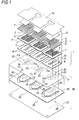
- Fig. 1 is an exploded perspective view for assembling showing the entire part of a recording head with fusible films omitted; and Fig. 2 is a sectional view showing a structure in the vicinity of a pressure generating chamber of a single actuator unit.
- reference numeral 2 denotes a first cover body, that is constructed of a zirconia thin plate having a thickness of about 10 ⁇ m and has drive electrodes 5 formed on a surface thereof so as to confront pressure generating chambers 4 that will be described later.
- Piezoelectric vibrators 3 made of PZT or the like are fixed on the electrodes 5.
- Each pressure generating chamber 4 contracts or expands in response to a flexural vibration of the corresponding piezoelectric vibrator 3 and thereby not only jets an ink droplet from a corresponding nozzle opening 28, but also sucks up ink from a common ink chamber 23 through an ink supply inlet 20.
- Reference numeral 7 denotes a spacer, which is constructed by forming through holes in a ceramic plate made of zirconia (ZrO 2 ) having a thickness suitable for forming the pressure generating chambers 4, e.g., 150 ⁇ m.
- the spacer 7 has both surfaces thereof sealed by a second cover body 8 that will be described later and by the first cover body 2 to form the pressure generating chambers 4, respectively.
- Reference numeral 8 denotes a second cover body, which is constructed by forming communication holes 9 and communication holes 10, which will be described later, in a ceramic plate made of zirconia or the like.
- Each communication hole 9 connects a corresponding ink supply inlet 20 and one end of a corresponding pressure generating chamber 4.
- Each communication hole 10 connects a corresponding nozzle opening 28 to the other end of the corresponding pressure generating chamber 4.
- the second cover body 8 is fixed to the other surface of the spacer 7.
- These members 2, 7, 8 are assembled to an actuator unit 1 by molding a clay-like ceramic material into predetermined shapes and by laminating and sintering the shapes without using any adhesive.
- Reference numeral 21 denotes an ink supply inlet forming substrate that serves also as an actuator unit 1 fixing substrate.
- a maximum rigidity is required for the ink supply inlet forming substrate 21 among the recording head forming members so that ink tank connecting members can also be arranged on the ink supply inlet forming substrate.
- metal such as a rust preventive steel or ceramic having ink repellency is selected as a material.
- Recesses 21a are formed on a surface of the ink supply inlet forming substrate 21 confronting the common ink chambers 23. Each recess 21a opens onto a position confronting the pressure generating chamber 4 and onto an outer side, i.e., toward the actuator unit 1 as shown in Figs. 2 and 3.
- Such a recess 21a is finished into a flat surface (Fig. 4 (c)) by forming a recess 40 in a surface confronting the common ink chamber 23 of the ink supply inlet forming substrate 21 (Fig. 4 (a)) and grinding a projection 41 on the other surface (Fig. 4 (b)) when a metal is used to form the ink supply inlet forming substrate 21.
- the technique involves the steps of: forming an etching protective coat 43 having a window 42 in a surface of the ink supply inlet forming substrate 21 confronting the common ink chamber (Fig. 5 (a)); forming a recess 44 by etching only a single surface (Fig. 5 (b)); and removing the etching protective coat 43 thereafter (Fig. 5 (c)).
- this technique involves the steps of: preparing a plate member formed by laminating and bonding two rust preventive metal thin plates 50, 51 through an adhesive film 52; and selectively removing a portion corresponding to the recess 21a of one of the metal thin plates 50 by etching with the adhesive film 52 as an etching stopper.
- this technique which is characterized as forming a thick-walled portion by electroforming while masking a portion corresponding to the recess 21a on a surface of the substrate.
- Fig. 7 there still is another technique, which involves the steps of: laminating and bonding two metal thin plates 50, 51 while interposing a PPS or PI film 54 between the two metal thin plates 50, 51 through adhesive films 55, 56; and selectively removing a portion corresponding to the recess 21a of one of the metal thin plates 50 by etching with the film 54 as an etching stopper.
- the ink supply inlet forming substrate 21 has the ink supply inlets 20 formed on one side of the pressure generating chambers 4 and communication holes 24 on the other side of the pressure generating chambers 4.
- Each ink supply inlet 20 connects the common ink chamber 23 to be described later to the corresponding pressure generating chamber 4.
- Each communication hole 24 connects the pressure generating chamber 4 to the corresponding nozzle opening 28.
- ink introducing ports 22, 22, 22 are formed at positions off an actuator unit 1 fixing region.
- the ink introducing ports allow the ink to flow in from a not shown ink tank.
- Reference numeral 25 denotes a common ink chamber forming substrate that is constructed by forming through holes and communication holes 26.
- the common ink chamber forming substrate 25 is constructed of a plate member having a thickness suitable for forming the common ink chambers 23, i.e., a corrosion resistant plate member such as a 150 ⁇ m-thick stainless steel.
- the through holes correspond to the shapes of the common ink chambers 23.
- Each communication hole 26 connects to a corresponding nozzle opening 28 formed in a nozzle plate 27.
- the ink supply inlet forming substrate 21, the common ink chamber forming substrate 25, and the nozzle plate 27 are assembled to a flow path unit 30 while fixed with adhesive layers 32, 33 such as fusible films or adhesives interposed therebetween.
- the fusible film 31 and the actuator unit 1 are sequentially laminated one upon another on a surface of the ink supply inlet forming substrate 21 of the flow path unit 30 as shown in Fig. 8 and thereafter heated while pressed, the flexible film 31 rapidly softens and fuses as the temperature of the bonding region increases rapidly.
- the heating causes the air confined between the fusible film 31 and the actuator unit 1/the flow path unit 30 to expand, an increase in pressure is reduced by a space formed by the recess 21a of the ink supply inlet forming substrate 21 and a window 31a of the fusible film 31. Therefore, the bonding surface can be bonded reliably.
- the recess 21a when a recess 21a having a length L of 8.73 mm, a width W of 1.74 mm, and a thin walled portion thickness ranging from 15 to 25 ⁇ m is formed in the ink supply inlet forming substrate 21, the recess 21a exhibits a resiliency of about 1 x 10 -15 m 3 /Pa. Therefore, the increase in pressure caused by thermally expanded air at the time of bonding can be sufficiently absorbed.
- a thickness T' (Fig. 2) of an air layer formed between the recess 21a and the adhesive layer functions as an appropriate vibration shielding member with respect to vibrations propagated from the actuator unit 1.
- This construction contributes to preventing the ink from being supplied to the pressure generating chambers 4 defectively. That is, vibrations caused at the pressure generating chambers 4 at the time of jetting ink droplets are propagated to the common ink chamber 23, and this propagation to the common ink chamber 23 induces vibrations to the ink in the common ink chamber, which in turn affects the supply of the ink to the pressure generating chambers.
- reference numeral 14 in Figs. 1 and 2 denotes a common electrode formed on the surface of the piezoelectric vibrator 3 and that reference numeral 15 denotes a flexible cable that connects the actuator unit to an external device.
- vibrations of the piezoelectric vibrator 3 transmitted through the actuator unit 1 reach the common ink chamber 23 after having being damped by reflection and absorption due to an extremely large difference in impedance caused by the air layer in the recess 21a of the ink supply inlet forming substrate 21. Therefore, transmission of vibrations inducing pressure fluctuations in other pressure generating chambers 4 through the common ink chamber 23, which has heretofore been a problem, can be reduced significantly.
- the bonding area between the ink supply inlet forming substrate 21 and the actuator unit 1 can be limited easily, the durability of the adhesive with respect to a heat cycle can be improved by absorbing a difference in thermal expansion caused by a difference in the materials of which both members are made.
- Fig. 9 shows an embodiment that is applicable to a case where the recess 21a is formed by etching one surface with two such metal thin plates 50, 51 bonded through the adhesive film 52.
- the position of the recess 21a is displaced by a predetermined distance ⁇ d with regard to the edge of the common ink chamber 23, so that the recess 21a is easy to flex at this region.
- the metal thin plates 50, 51 and the layer formed of the fusible film 52 are resiliently deformed integrally even if stresses are applied to part of the recess 21a with pressure being applied during the fusing operation. Therefore, promotion of the separation of the thin plate 50 due to expansion of the air can be controlled by preventing intensive stress concentration at the boundary 51a.
- Fig. 11 shows another embodiment that is applied to avoid the problem caused when two metal thin plates 50, 51 are bonded through the adhesive film 52.
- a plurality of recesses 21b, 21c, 21d are formed by etching the metal thin plate 50 to be etched in such a manner that ribs 50b, 50c extending in the width direction are left arranged at a predetermined interval in the nozzle opening arrangement direction. More preferably, intervals L1, L2, L3 at which the ribs 50b, 50c are positioned are increased (L1 ⁇ L2 ⁇ L3) with increasing distance from the ink introducing port 22.
- the metal thin plate 50 and the adhesive film 52 are relatively susceptible to be separated from each other along the boundaries of the recesses 21b, 21c, 21d in the longitudinal direction due to receiving stresses.
- the boundaries in the longitudinal direction are designed so as to mutually be pulled toward each other by the ribs 50b, 50c. Therefore, the floating of the metal thin plate 50 from the adhesive film 52 can be prevented.
- the intervals L1, L2, L3 at which the ribs 50b, 50c are arranged are increased as the ribs 50b, 50c get away from the ink introducing port 22, and the area of the recess 21d that is the remotest from the ink introducing port 22 is increased. Therefore, separation can be prevented without controling compliance in the depth of the common ink chamber uselessly.
- Fig. 12 shows another embodiment that is designed to prevent the separation.
- projections 50d, 50d ⁇ ⁇ are arranged at a predetermined interval along the boundaries of the metal thin plate 50 in the longitudinal direction confronting the recesses 21a, the metal thin plate 50 forming the recesses 21a.
- the bonding area at the boundaries can be increased by the projections 50d, 50d ⁇ ⁇ , which in turn prevents separation.
- shallow recesses 21e, 21f can be formed so as to confront each other from both surfaces of the ink supply inlet forming substrate 21 as shown in Fig. 13 if it is difficult to machine a deep recess 21a in the ink supply inlet forming substrate 21 with high accuracy.
- This embodiment can also absorb pressure increase caused by thermal expansion at the time of the fusing operation using one of the recesses 21e.
- not only propagation of vibrations from the actuator unit 1 to the common ink chamber can be prevented together with the other recess 21f, but also the bonding area of the actuator unit 1 is reduced as much as possible to thereby allow the thermal expansion differences to be absorbed.
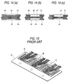
- such ink supply inlet forming substrate can be formed by arranging etching protective coats 43, 46 having windows 42, 45 at positions confronting the recesses 21e, 21f of the ink supply inlet forming substrate 21 on both surfaces thereof (Fig. 14 (a)), forming the recesses 21e, 21f by etching both surfaces thereafter (Fig. 14 (b)), and removing the etching protective coats 43, 46 (Fig. 14 (c)).
- the arrangement of the recesses 21e, 21f on both surfaces is helpful not only in shortening the machining time as well as ensuring accuracy because the etching depth is small.
- the pressure generating means comprises the first cover body 2, the piezoelectric vibrators 3 and the drive electrodes 5 as shown in Figs. 1 and 2.
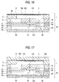
- the pressure generating means which comprises piezoelectric vibrating plates 100, lower electrodes 101 and upper electrodes 102 so as to seal a surface of the spacer 7 may be applied as shown in Fig. 16.
- the pressure generating means comprising cover plates 106, electrically conductive layer 103, heating elements 104 and protective layer 105 may be used as shown in Fig. 17.
- Other constitutions which make the pressure in the pressure generating chamber change may be used for the present invention.
- the invention is characterized as reducing pressure by allowing the recess to release the thermally expanded air during bonding into a surface of the ink supply inlet forming substrate confronting the actuator unit, and the bonding area is reduced to a minimum to allow thermal expansion differences between both members to be absorbed by the adhesive layer.
- the air layer formed by the recess functions as a vibration shielding member, which in turn contributes to preventing the propagation of vibrations from the piezoelectric vibrators to the common ink chamber.
Landscapes
- Engineering & Computer Science (AREA)
- Manufacturing & Machinery (AREA)
- Particle Formation And Scattering Control In Inkjet Printers (AREA)
Abstract
Description
- The invention relates to a laminated ink jet recording head.
- For example, as shown in Japanese Patent Publication No. Hei. 6-40035, an ink jet recording head is designed so that piezoelectric vibrators are stuck to a part of a resilient plate forming a pressure generating chamber and the volume of each pressure generating chamber is changed by flexural displacement of the corresponding piezoelectric vibrator. Therefore, the ink jet recording head can displace a wide area of the pressure generating chamber. Therefore, such an ink jet recording head can produce ink droplets stably.
- As shown in Fig. 15, such a recording head can be roughly divided into actuator units A, B, C and a single flow path unit D. The plurality of actuator units A, B, C are prepared by sintering a ceramic material into pressure generating chambers, vibration plates, and piezoelectric vibrators. The flow path unit D is made of a metal plate formed so as to correspond to a plurality of arrays of nozzle openings. The plurality of actuator units A, B, C and the flow path unit D are fixed to one another using an adhesive.
- As described above, the plurality of actuator units are fixed to the flow path unit by means of a thermally fusing method in which a fusible film is interposed between the actuator units and the flow path unit and in which the fusible film is fused by heating with pressure being applied thereto.
- However, since the bonding area is large, the air contained between the fusible film and the actuator units/the flow path unit expands and thereby causes defective bonding. Further, since the materials are heated for a long period of time, a difference in thermal expansion due to a difference in materials causes warp and the like.
- In addition to these problems, with a progress in the downsizing of recording heads, the problem of so-called "crosstalk" occurs because vibrations of the piezoelectric vibrators propagate to the common ink chambers, and this in turn causes the meniscuses of the other pressure generating chambers through the ink in the common ink chamber. As a result, the problem of impaired printing quality, e.g., is encountered.
- The present invention intends to overcome the aforementioned problems. The object is solved by the laminated ink jet recording head according to
independent claim 1. Further advantages, features, aspects and details of the invention are evident from the dependent claims, the description and the accompanying drawings. The claims are intended to be understood as a first non-limiting approach of defining the invention in general terms. - The invention generally relates to a laminated ink jet recording head formed by bonding an actuator unit made of ceramic and a flow path substrate formed of metal together.
- An aspect of the invention is therefore to provide a laminated ink jet recording head that can give a solution to the inconvenience attributable to thermal bonding between the flow path unit and the actuator unit as well as the problem of crosstalk and the like at once.
- There is provided a laminated ink jet recording head comprising: an actuator unit having a piezoelectric vibrator on one surface thereof and a pressure generating chamber formed therein; and a flow path unit laminated on another surface of the actuator unit with a first surface thereof, the flow path unit having a common ink chamber formed therein; wherein a recess is formed on the first surface of the flow path unit in such a manner that the recess confronts said common ink chamber.
- Since the recess of the flow path unit provides a space with respect to the actuator unit, the thermally expanded air is released into this recess to thereby reduce pressure. In addition, the air layer formed by the recess shields the propagation of vibrations from the piezoelectric vibration elements to the common ink chambers.
- The invention will be better understood by reference to the following description of embodiments of the invention taken in conjunction with the accompanying drawings, wherein
- Fig. 1 is an exploded perspective view for assembling an ink jet recording head which is an embodiment of the invention;
- Fig. 2 is a sectional view of the ink jet recording head shown in Fig. 1;
- Fig. 3 is a diagram showing a positional relationship between recesses and a common ink chamber formed in an ink supply inlet forming substrate;
- Figs. 4(a) to 4(c) are diagrams showing a process for forming a recess in the ink supply inlet forming substrate;
- Figs. 5(a) to 5(c) are diagrams showing another exemplary process for forming a recess in the ink supply inlet forming substrate;
- Fig. 6 is a sectional view showing another exemplary ink supply inlet forming substrate;
- Fig. 7 is a sectional view showing another exemplary ink supply inlet forming substrate;
- Fig. 8 is a diagram showing a process for bonding the actuator unit to a flow path unit;
- Fig. 9 is a sectional view showing an embodiment of the invention using an ink supply inlet forming substrate formed by bonding two thin plates together;
- Fig. 10 is a diagram showing the vicinity of a recess in enlarged form;
- Fig. 11 is a plan view showing another embodiment of the invention using an ink supply inlet forming substrate formed by bonding two thin plates together;
- Fig. 12 is a plan view showing another embodiment of the invention using an ink supply inlet forming substrate formed by bonding two thin plates together;
- Fig. 13 is a sectional view showing an ink jet recording head, which is another embodiment of the invention, in the form of a structure in the vicinity of a pressure generating chamber of a single actuator unit;
- Figs. 14(a) to 14(c) are diagrams showing an exemplary process for fabricating an ink supply inlet forming substrate of the recording head shown in Fig. 13;
- Fig. 15 is a perspective view showing an ink jet recording head of the prior art having a plurality of actuator units on a flow path unit;
- Fig. 16 is a sectional view showing an ink jet recording head, which is another embodiment of the invention, in the form of a structure in the vicinity of a pressure generating chamber of a single actuator unit; and
- Fig. 17 is a sectional view showing an ink jet recording head, which is still another embodiment of the invention, in the form of a structure in the vicinity of a pressure generating chamber of a single actuator unit.
- Fig. 1 is an exploded perspective view for assembling showing the entire part of a recording head with fusible films omitted; and Fig. 2 is a sectional view showing a structure in the vicinity of a pressure generating chamber of a single actuator unit. In Figs. 1 and 2,
reference numeral 2 denotes a first cover body, that is constructed of a zirconia thin plate having a thickness of about 10 µm and has driveelectrodes 5 formed on a surface thereof so as to confrontpressure generating chambers 4 that will be described later.Piezoelectric vibrators 3 made of PZT or the like are fixed on theelectrodes 5. - Each
pressure generating chamber 4 contracts or expands in response to a flexural vibration of the correspondingpiezoelectric vibrator 3 and thereby not only jets an ink droplet from a corresponding nozzle opening 28, but also sucks up ink from acommon ink chamber 23 through anink supply inlet 20. -
Reference numeral 7 denotes a spacer, which is constructed by forming through holes in a ceramic plate made of zirconia (ZrO2) having a thickness suitable for forming thepressure generating chambers 4, e.g., 150 µm. Thespacer 7 has both surfaces thereof sealed by asecond cover body 8 that will be described later and by thefirst cover body 2 to form thepressure generating chambers 4, respectively. -
Reference numeral 8 denotes a second cover body, which is constructed by formingcommunication holes 9 andcommunication holes 10, which will be described later, in a ceramic plate made of zirconia or the like. Eachcommunication hole 9 connects a correspondingink supply inlet 20 and one end of a correspondingpressure generating chamber 4. Eachcommunication hole 10 connects a corresponding nozzle opening 28 to the other end of the correspondingpressure generating chamber 4. Thesecond cover body 8 is fixed to the other surface of thespacer 7. - These
members actuator unit 1 by molding a clay-like ceramic material into predetermined shapes and by laminating and sintering the shapes without using any adhesive. -
Reference numeral 21 denotes an ink supply inlet forming substrate that serves also as anactuator unit 1 fixing substrate. A maximum rigidity is required for the ink supplyinlet forming substrate 21 among the recording head forming members so that ink tank connecting members can also be arranged on the ink supply inlet forming substrate. As a result, metal such as a rust preventive steel or ceramic having ink repellency is selected as a material. -
Recesses 21a are formed on a surface of the ink supplyinlet forming substrate 21 confronting thecommon ink chambers 23. Eachrecess 21a opens onto a position confronting thepressure generating chamber 4 and onto an outer side, i.e., toward theactuator unit 1 as shown in Figs. 2 and 3. - Such a
recess 21a is finished into a flat surface (Fig. 4 (c)) by forming arecess 40 in a surface confronting thecommon ink chamber 23 of the ink supply inlet forming substrate 21 (Fig. 4 (a)) and grinding aprojection 41 on the other surface (Fig. 4 (b)) when a metal is used to form the ink supplyinlet forming substrate 21. - Another technique may be also applicable. The technique involves the steps of: forming an etching
protective coat 43 having awindow 42 in a surface of the ink supplyinlet forming substrate 21 confronting the common ink chamber (Fig. 5 (a)); forming arecess 44 by etching only a single surface (Fig. 5 (b)); and removing the etchingprotective coat 43 thereafter (Fig. 5 (c)). - Still another technique is also applicable. As shown in Fig. 6, this technique involves the steps of: preparing a plate member formed by laminating and bonding two rust preventive metal
thin plates adhesive film 52; and selectively removing a portion corresponding to therecess 21a of one of the metalthin plates 50 by etching with theadhesive film 52 as an etching stopper. There still is another technique, which is characterized as forming a thick-walled portion by electroforming while masking a portion corresponding to therecess 21a on a surface of the substrate. - As shown in Fig. 7, there still is another technique, which involves the steps of: laminating and bonding two metal
thin plates thin plates adhesive films recess 21a of one of the metalthin plates 50 by etching with the film 54 as an etching stopper. - As shown in Figs. 1 and 2, the ink supply
inlet forming substrate 21 has theink supply inlets 20 formed on one side of thepressure generating chambers 4 andcommunication holes 24 on the other side of thepressure generating chambers 4. Eachink supply inlet 20 connects thecommon ink chamber 23 to be described later to the correspondingpressure generating chamber 4. Eachcommunication hole 24 connects thepressure generating chamber 4 to thecorresponding nozzle opening 28. - Further,
ink introducing ports actuator unit 1 fixing region. The ink introducing ports allow the ink to flow in from a not shown ink tank. -
Reference numeral 25 denotes a common ink chamber forming substrate that is constructed by forming through holes and communication holes 26. The common inkchamber forming substrate 25 is constructed of a plate member having a thickness suitable for forming thecommon ink chambers 23, i.e., a corrosion resistant plate member such as a 150 µm-thick stainless steel. The through holes correspond to the shapes of thecommon ink chambers 23. Eachcommunication hole 26 connects to a corresponding nozzle opening 28 formed in anozzle plate 27. - The ink supply
inlet forming substrate 21, the common inkchamber forming substrate 25, and thenozzle plate 27 are assembled to aflow path unit 30 while fixed withadhesive layers - When the
fusible film 31 and theactuator unit 1 are sequentially laminated one upon another on a surface of the ink supplyinlet forming substrate 21 of theflow path unit 30 as shown in Fig. 8 and thereafter heated while pressed, theflexible film 31 rapidly softens and fuses as the temperature of the bonding region increases rapidly. - Although the heating causes the air confined between the
fusible film 31 and theactuator unit 1/theflow path unit 30 to expand, an increase in pressure is reduced by a space formed by therecess 21a of the ink supplyinlet forming substrate 21 and awindow 31a of thefusible film 31. Therefore, the bonding surface can be bonded reliably. - For example, when a
recess 21a having a length L of 8.73 mm, a width W of 1.74 mm, and a thin walled portion thickness ranging from 15 to 25 µm is formed in the ink supplyinlet forming substrate 21, therecess 21a exhibits a resiliency of about 1 x 10-15 m3/Pa. Therefore, the increase in pressure caused by thermally expanded air at the time of bonding can be sufficiently absorbed. - Further, a thickness T' (Fig. 2) of an air layer formed between the
recess 21a and the adhesive layer functions as an appropriate vibration shielding member with respect to vibrations propagated from theactuator unit 1. This construction contributes to preventing the ink from being supplied to thepressure generating chambers 4 defectively. That is, vibrations caused at thepressure generating chambers 4 at the time of jetting ink droplets are propagated to thecommon ink chamber 23, and this propagation to thecommon ink chamber 23 induces vibrations to the ink in the common ink chamber, which in turn affects the supply of the ink to the pressure generating chambers. - It may be noted that
reference numeral 14 in Figs. 1 and 2 denotes a common electrode formed on the surface of thepiezoelectric vibrator 3 and thatreference numeral 15 denotes a flexible cable that connects the actuator unit to an external device. - When a drive signal is applied to a
piezoelectric vibrator 3 in this embodiment, thepiezoelectric vibrator 3 vibrates in flexure to contract the correspondingpressure generating chamber 4. As a result, pressure is applied to the ink within thepressure generating chamber 4 to thereby drive an ink droplet out of thecorresponding nozzle opening 28. - At this moment, vibrations of the
piezoelectric vibrator 3 transmitted through theactuator unit 1 reach thecommon ink chamber 23 after having being damped by reflection and absorption due to an extremely large difference in impedance caused by the air layer in therecess 21a of the ink supplyinlet forming substrate 21. Therefore, transmission of vibrations inducing pressure fluctuations in otherpressure generating chambers 4 through thecommon ink chamber 23, which has heretofore been a problem, can be reduced significantly. - Further, since the bonding area between the ink supply
inlet forming substrate 21 and theactuator unit 1 can be limited easily, the durability of the adhesive with respect to a heat cycle can be improved by absorbing a difference in thermal expansion caused by a difference in the materials of which both members are made. - By the way, as shown in Fig. 6, if plate members formed by laminating and bonding two metal
thin plates adhesive film 52 are prepared and the portion corresponding to therecess 21a of the metalthin plate 50 is selectively removed by etching with theadhesive film 52 as an etching stopper, theboundary 51a of therecess 21a is exposed and it is therefore likely that the adhesive strength of theboundary 51a is slightly reduced because the etching solution affects this region. - When the
actuator unit 1 is heated and bonded while receiving pressure with thefusible film 31 placed on the surface of the metalthin plate 50 under this condition, stresses concentrate on this boundary to cause separation. There also is the possibility that the air contained between thefusible film 31 and theactuator unit 1/theflow path unit 30 will thermally expand and enter into the depth from theboundary 51a to thereby cause large separation. - Fig. 9 shows an embodiment that is applicable to a case where the
recess 21a is formed by etching one surface with two such metalthin plates adhesive film 52. The position of therecess 21a is displaced by a predetermined distance Δd with regard to the edge of thecommon ink chamber 23, so that therecess 21a is easy to flex at this region. - According to this embodiment, the metal
thin plates fusible film 52 are resiliently deformed integrally even if stresses are applied to part of therecess 21a with pressure being applied during the fusing operation. Therefore, promotion of the separation of thethin plate 50 due to expansion of the air can be controlled by preventing intensive stress concentration at theboundary 51a. - Fig. 11 shows another embodiment that is applied to avoid the problem caused when two metal
thin plates adhesive film 52. In this embodiment, a plurality ofrecesses thin plate 50 to be etched in such a manner thatribs ribs ink introducing port 22. - The metal
thin plate 50 and theadhesive film 52 are relatively susceptible to be separated from each other along the boundaries of therecesses ribs thin plate 50 from theadhesive film 52 can be prevented. Further, the intervals L1, L2, L3 at which theribs ribs ink introducing port 22, and the area of therecess 21d that is the remotest from theink introducing port 22 is increased. Therefore, separation can be prevented without controling compliance in the depth of the common ink chamber uselessly. - Fig. 12 shows another embodiment that is designed to prevent the separation. In this embodiment,
projections thin plate 50 in the longitudinal direction confronting therecesses 21a, the metalthin plate 50 forming therecesses 21a. - According to this embodiment, the bonding area at the boundaries can be increased by the
projections - It may be noted that
shallow recesses inlet forming substrate 21 as shown in Fig. 13 if it is difficult to machine adeep recess 21a in the ink supplyinlet forming substrate 21 with high accuracy. - This embodiment can also absorb pressure increase caused by thermal expansion at the time of the fusing operation using one of the
recesses 21e. In addition, not only propagation of vibrations from theactuator unit 1 to the common ink chamber can be prevented together with theother recess 21f, but also the bonding area of theactuator unit 1 is reduced as much as possible to thereby allow the thermal expansion differences to be absorbed. - As shown in Figs. 14(a) to 14(c), such ink supply inlet forming substrate can be formed by arranging etching
protective coats windows recesses inlet forming substrate 21 on both surfaces thereof (Fig. 14 (a)), forming therecesses protective coats 43, 46 (Fig. 14 (c)). - The arrangement of the
recesses - In the aforementioned actuator unit, the pressure generating means comprises the
first cover body 2, thepiezoelectric vibrators 3 and thedrive electrodes 5 as shown in Figs. 1 and 2. Alternatively, the pressure generating means which comprises piezoelectric vibratingplates 100,lower electrodes 101 andupper electrodes 102 so as to seal a surface of thespacer 7 may be applied as shown in Fig. 16. Furthermore, the pressure generating means comprisingcover plates 106, electricallyconductive layer 103,heating elements 104 andprotective layer 105 may be used as shown in Fig. 17. Other constitutions which make the pressure in the pressure generating chamber change may be used for the present invention. - As described in the foregoing, the invention is characterized as reducing pressure by allowing the recess to release the thermally expanded air during bonding into a surface of the ink supply inlet forming substrate confronting the actuator unit, and the bonding area is reduced to a minimum to allow thermal expansion differences between both members to be absorbed by the adhesive layer. Further, since the recess is formed in a region confronting the pressure generating chamber, the air layer formed by the recess functions as a vibration shielding member, which in turn contributes to preventing the propagation of vibrations from the piezoelectric vibrators to the common ink chamber.
Claims (14)
- A laminated ink jet recording head comprising:an actuator unit (1) having at least a pressure generating chamber (4) and pressure generating means formed therein; anda flow path unit (30) on which the actuator unit (1) is laminated, the flow path unit (30) having at least a common ink chamber (23) formed therein;wherein a recess (21a; 40; 44) is formed on a surface of the flow path unit (30) in such a manner that the recess (21a; 40; 44) confronts said common ink chamber (23).
- The laminated ink jet recording head according to claim 1, wherein the recess (21a; 40; 44) is formed in a region confronting the pressure generating chamber (4).
- The laminated ink jet recording head according to claim 1 or 2, wherein the actuator unit (1) comprises: a first cover body (2) in which the pressure generating means is formed; and/or a spacer (7), a surface of which is sealed by the first cover body (2) so as to form the pressure generating chamber (4).
- The laminated ink jet recording head according to claim 3, wherein the actuator unit further comprises a second cover body (8) sealing another surface of the spacer (7) and having a communication hole (9) which communicates at least with the common ink chamber (23).
- The laminated ink jet recording head according to one of the preceding claims wherein the flow path unit (30) comprises: an ink supply inlet forming substrate (21) in which the recess (21a; 40; 44) is formed on one surface thereof; and/or a common ink chamber forming substrate (25) laminated on the ink supply inlet forming substrate (21) and having the common ink chamber (23) formed therein; and/or a nozzle plate (27) laminated on the common ink chamber forming substrate (25) and having a nozzle opening (28).
- The laminated ink jet recording head according to claim 5, wherein the ink supply inlet forming substrate (21) is formed by bonding two metal thin plates (50, 51) together through an adhesive layer (52); and the recess (21a) is formed by partially removing one of the metal thin plates (50, 51).
- The laminated ink jet recording head according to one of the preceding claims, wherein a circumferential edge of the recess (21a; 40; 44) is arranged so as to be displaced inside the common ink chamber (23) from the edge of the common ink chamber (23).
- The laminated ink jet recording head according to one of the preceding claims, wherein the recess (21a) is formed so as to be split into a plurality of regions in the arrangement direction of the nozzle opening (28).
- The laminated ink jet recording head according to claim 8, wherein an area of each of the split regions is set so as to increase with increasing distance from an ink flowing port into which ink is introduced from an external source.
- The laminated ink jet recording head according to one of the preceding claims, wherein a plurality of projections (41; 50d) projecting inside the recess (21a; 40; 44) for forming the recess are formed in the circumferential edge of the recess (21a; 40; 44).
- The laminated ink jet recording head according to one of claims 5 to 10 wherein a second recess (47) is formed on another surface of the ink supply inlet forming substrate (21) at the back of the recess (44).
- The laminated ink jet recording head according to one of claims 5 to 11, wherein the ink supply inlet forming substrate (21) is formed by bonding two metal thin plates (50, 51) together through an adhesive layer (52); and/or the recess (21a) is formed by partially removing one of the metal thin plates (50, 51) with the adhesive layer (52) as an etching stopper.
- The laminated ink jet recording head according to one of claims 5 to 11, wherein the ink supply inlet forming substrate (21) is formed by bonding two metal thin plates (50, 51) while interposing a plastic film (54) between the two metal thin plates (50, 51) through two adhesive layers (55, 56); and the recess (21a) is formed by partially removing one of the metal thin plates (50, 51) with the plastic film (54) as an etching stopper.
- The laminated ink jet recording head according to one of the preceding claims, wherein the actuator unit (1) and flow path unit (30) are bonded through a fusible film (31) in which a window (31a) is provided in a region confronting the recess (21a; 40; 44).
Applications Claiming Priority (6)
| Application Number | Priority Date | Filing Date | Title |
|---|---|---|---|
| JP23761195 | 1995-08-23 | ||
| JP237611/95 | 1995-08-23 | ||
| JP23761195 | 1995-08-23 | ||
| JP9919696 | 1996-03-28 | ||
| JP99196/96 | 1996-03-28 | ||
| JP9919696 | 1996-03-28 |
Publications (3)
| Publication Number | Publication Date |
|---|---|
| EP0759361A2 true EP0759361A2 (en) | 1997-02-26 |
| EP0759361A3 EP0759361A3 (en) | 1998-03-18 |
| EP0759361B1 EP0759361B1 (en) | 2000-04-19 |
Family
ID=26440348
Family Applications (1)
| Application Number | Title | Priority Date | Filing Date |
|---|---|---|---|
| EP96113563A Expired - Lifetime EP0759361B1 (en) | 1995-08-23 | 1996-08-23 | Laminated ink jet recording head |
Country Status (4)
| Country | Link |
|---|---|
| US (1) | US5963234A (en) |
| EP (1) | EP0759361B1 (en) |
| DE (1) | DE69607796T2 (en) |
| HK (1) | HK1011664A1 (en) |
Cited By (12)
| Publication number | Priority date | Publication date | Assignee | Title |
|---|---|---|---|---|
| EP0916497A3 (en) * | 1997-11-06 | 1999-12-22 | Seiko Epson Corporation | Ink-jet recording head |
| EP1312797A1 (en) * | 2001-11-16 | 2003-05-21 | Ngk Insulators, Ltd. | Liquid fuel injection system |
| EP1336487A2 (en) * | 2002-02-15 | 2003-08-20 | Brother Kogyo Kabushiki Kaisha | Ink-jet head |
| EP1506863A1 (en) * | 2003-08-12 | 2005-02-16 | Brother Kogyo Kabushiki Kaisha | Inkjet print head |
| EP1547775A1 (en) * | 2003-12-25 | 2005-06-29 | Brother Kogyo Kabushiki Kaisha | Inkjet Head |
| US7159970B2 (en) | 2003-08-14 | 2007-01-09 | Brother Kogyo Kabushiki Kaisha | Ink-jet head |
| US7252370B2 (en) | 2003-06-30 | 2007-08-07 | Brother Kogyo Kabushiki Kaisha | Inkjet printing head |
| US7266868B2 (en) | 2003-06-30 | 2007-09-11 | Brother Kogyo Kabushiki Kaisha | Method of manufacturing liquid delivery apparatus |
| US7396111B2 (en) | 2003-08-11 | 2008-07-08 | Brother Kogyo Kabushiki Kaisha | Inkjet head and inkjet printer |
| US9056458B2 (en) | 2011-05-28 | 2015-06-16 | Kyocera Corporation | Liquid discharge head and recording device using same |
| EP3053744A1 (en) * | 2015-02-09 | 2016-08-10 | Seiko Epson Corporation | Liquid ejecting head and liquid ejecting apparatus |
| EP3318408A4 (en) * | 2015-07-30 | 2018-07-25 | Kyocera Corporation | Liquid discharge head and recording device using same |
Families Citing this family (36)
| Publication number | Priority date | Publication date | Assignee | Title |
|---|---|---|---|---|
| US6260963B1 (en) * | 1999-01-15 | 2001-07-17 | Xerox Corporation | Ink jet print head with damping feature |
| JP3570495B2 (en) * | 1999-01-29 | 2004-09-29 | セイコーエプソン株式会社 | Ink jet recording head |
| US6604817B2 (en) * | 2000-03-07 | 2003-08-12 | Brother Kogyo Kabushiki Kaisha | Print head for piezoelectric ink jet printer, piezoelectric actuator therefor, and process for producing piezoelectric actuator |
| KR100527221B1 (en) | 2000-03-13 | 2005-11-08 | 세이코 엡슨 가부시키가이샤 | Inkjet head and inkjet printer |
| US6786658B2 (en) * | 2000-05-23 | 2004-09-07 | Silverbrook Research Pty. Ltd. | Printer for accommodating varying page thicknesses |
| US6409323B1 (en) * | 2000-05-23 | 2002-06-25 | Silverbrook Research Pty Ltd | Laminated ink distribution assembly for a printer |
| US6488422B1 (en) * | 2000-05-23 | 2002-12-03 | Silverbrook Research Pty Ltd | Paper thickness sensor in a printer |
| US6526658B1 (en) | 2000-05-23 | 2003-03-04 | Silverbrook Research Pty Ltd | Method of manufacture of an ink jet printhead having a moving nozzle with an externally arranged actuator |
| US7213989B2 (en) * | 2000-05-23 | 2007-05-08 | Silverbrook Research Pty Ltd | Ink distribution structure for a printhead |
| US6988840B2 (en) * | 2000-05-23 | 2006-01-24 | Silverbrook Research Pty Ltd | Printhead chassis assembly |
| US6652078B2 (en) * | 2000-05-23 | 2003-11-25 | Silverbrook Research Pty Ltd | Ink supply arrangement for a printer |
| CN1623784B (en) * | 2000-05-24 | 2010-05-26 | 西尔弗布鲁克研究有限公司 | Printing head assembly with ink dispenser |
| AU2005200473B1 (en) * | 2000-05-24 | 2005-03-03 | Memjet Technology Limited | Printhead assembly having ink distribution structures |
| AU2004220748B2 (en) * | 2000-05-24 | 2004-11-25 | Memjet Technology Limited | Pagewidth inkjet printer with an ink distribution assembly |
| SG149677A1 (en) * | 2000-05-24 | 2009-02-27 | Silverbrook Res Pty Ltd | A printhead assembly with an ink distribution arrangement |
| AU2005201831B2 (en) * | 2000-05-24 | 2006-01-05 | Zamtec Limited | Printhead assembly having ink distribution structures |
| AU2000247329B2 (en) * | 2000-05-24 | 2004-04-08 | Memjet Technology Limited | Laminated ink distribution assembly for a printer |
| JP4075317B2 (en) * | 2001-04-11 | 2008-04-16 | 富士ゼロックス株式会社 | Inkjet recording head and inkjet recording apparatus |
| US6592216B2 (en) * | 2001-06-25 | 2003-07-15 | Xerox Corporation | Ink jet print head acoustic filters |
| US20030099379A1 (en) * | 2001-11-26 | 2003-05-29 | Monk Bruce C. | Validation and verification apparatus and method |
| JP4272381B2 (en) * | 2002-02-22 | 2009-06-03 | パナソニック株式会社 | Ink jet head and recording apparatus |
| JP2004174827A (en) * | 2002-11-26 | 2004-06-24 | Brother Ind Ltd | Ink jet printer head and its head unit |
| JP2005096350A (en) * | 2003-09-26 | 2005-04-14 | Brother Ind Ltd | Manufacturing method for inkjet printer head |
| US7618647B2 (en) * | 2003-10-03 | 2009-11-17 | Boston Scientific Scimed, Inc. | Using bucky paper as a therapeutic aid in medical applications |
| US7322672B2 (en) * | 2004-01-21 | 2008-01-29 | Silverbrook Research Pty Ltd | Printhead assembly with combined securing and mounting arrangement for components |
| US7118192B2 (en) * | 2004-01-21 | 2006-10-10 | Silverbrook Research Pty Ltd | Printhead assembly with support for print engine controller |
| US7083271B2 (en) * | 2004-01-21 | 2006-08-01 | Silverbrook Research Pty Ltd | Printhead module with laminated fluid distribution stack |
| US7267431B2 (en) * | 2004-06-30 | 2007-09-11 | Lexmark International, Inc. | Multi-fluid ejection device |
| JP4306605B2 (en) * | 2004-12-22 | 2009-08-05 | ブラザー工業株式会社 | Inkjet head manufacturing method |
| JP2008023768A (en) * | 2006-07-19 | 2008-02-07 | Brother Ind Ltd | Method for managing thickness of head unit and method for manufacturing head unit |
| JP2008143127A (en) * | 2006-12-13 | 2008-06-26 | Canon Inc | Recording head and recording device |
| US7758163B2 (en) * | 2007-04-30 | 2010-07-20 | Hewlett-Packard Development Company, L.P. | Base and substrate for printhead assembly |
| JP6083986B2 (en) * | 2012-04-27 | 2017-02-22 | キヤノン株式会社 | Liquid discharge head |
| JP5995718B2 (en) * | 2012-12-28 | 2016-09-21 | エスアイアイ・プリンテック株式会社 | Head chip, head chip manufacturing method, liquid ejecting head, and liquid ejecting apparatus |
| CN109968816B (en) * | 2017-12-27 | 2021-01-19 | 精工爱普生株式会社 | Flow channel structure, liquid discharge head, and liquid discharge apparatus |
| EP4082798A4 (en) * | 2019-12-27 | 2024-01-31 | Kyocera Corp | Liquid discharge head and recording device |
Citations (5)
| Publication number | Priority date | Publication date | Assignee | Title |
|---|---|---|---|---|
| JPS5998859A (en) * | 1982-11-30 | 1984-06-07 | Seiko Epson Corp | Ink jet head |
| JPH04179549A (en) * | 1990-11-14 | 1992-06-26 | Seiko Epson Corp | Ink jet head |
| EP0584823A1 (en) * | 1992-08-26 | 1994-03-02 | Seiko Epson Corporation | Ink jet recording head and manufacturing method therefor |
| EP0670218A2 (en) * | 1994-03-03 | 1995-09-06 | Fujitsu Limited | Ink jet head |
| JPH0939242A (en) * | 1995-07-27 | 1997-02-10 | Seiko Epson Corp | Laminated ink jet type recording head |
Family Cites Families (5)
| Publication number | Priority date | Publication date | Assignee | Title |
|---|---|---|---|---|
| JPS6119367A (en) * | 1984-07-05 | 1986-01-28 | Canon Inc | Liquid injection recording head |
| JP3351436B2 (en) * | 1991-08-21 | 2002-11-25 | セイコーエプソン株式会社 | Two-part adhesive sheet material having pores |
| JP3144949B2 (en) * | 1992-05-27 | 2001-03-12 | 日本碍子株式会社 | Piezoelectric / electrostrictive actuator |
| JP3212382B2 (en) * | 1992-10-01 | 2001-09-25 | 日本碍子株式会社 | Precision brazing method |
| US5574486A (en) * | 1993-01-13 | 1996-11-12 | Tektronix, Inc. | Ink jet print heads and methos for preparing them |
-
1996
- 1996-08-20 US US08/700,028 patent/US5963234A/en not_active Expired - Lifetime
- 1996-08-23 EP EP96113563A patent/EP0759361B1/en not_active Expired - Lifetime
- 1996-08-23 DE DE69607796T patent/DE69607796T2/en not_active Expired - Lifetime
-
1998
- 1998-12-08 HK HK98112934A patent/HK1011664A1/en not_active IP Right Cessation
Patent Citations (5)
| Publication number | Priority date | Publication date | Assignee | Title |
|---|---|---|---|---|
| JPS5998859A (en) * | 1982-11-30 | 1984-06-07 | Seiko Epson Corp | Ink jet head |
| JPH04179549A (en) * | 1990-11-14 | 1992-06-26 | Seiko Epson Corp | Ink jet head |
| EP0584823A1 (en) * | 1992-08-26 | 1994-03-02 | Seiko Epson Corporation | Ink jet recording head and manufacturing method therefor |
| EP0670218A2 (en) * | 1994-03-03 | 1995-09-06 | Fujitsu Limited | Ink jet head |
| JPH0939242A (en) * | 1995-07-27 | 1997-02-10 | Seiko Epson Corp | Laminated ink jet type recording head |
Non-Patent Citations (3)
| Title |
|---|
| PATENT ABSTRACTS OF JAPAN vol. 008, no. 210 (M-328), 26 September 1984 & JP 59 098859 A (EPUSON KK), 7 June 1984, * |
| PATENT ABSTRACTS OF JAPAN vol. 016, no. 487 (M-1323), 9 October 1992 & JP 04 179549 A (SEIKO EPSON CORP), 26 June 1992, * |
| PATENT ABSTRACTS OF JAPAN vol. 097, no. 006, 30 June 1997 & JP 09 039242 A (SEIKO EPSON CORP), 10 February 1997, * |
Cited By (22)
| Publication number | Priority date | Publication date | Assignee | Title |
|---|---|---|---|---|
| US6190006B1 (en) | 1997-11-06 | 2001-02-20 | Seiko Epson Corporation | Ink-jet recording head |
| EP0916497A3 (en) * | 1997-11-06 | 1999-12-22 | Seiko Epson Corporation | Ink-jet recording head |
| US6845759B2 (en) | 2001-11-16 | 2005-01-25 | Ngk Insulators, Ltd. | Liquid fuel injection system |
| EP1312797A1 (en) * | 2001-11-16 | 2003-05-21 | Ngk Insulators, Ltd. | Liquid fuel injection system |
| US6830325B2 (en) | 2002-02-15 | 2004-12-14 | Brother Kogyo Kabushiki Kaisha | Ink-jet head |
| EP1336486A3 (en) * | 2002-02-15 | 2004-03-17 | Brother Kogyo Kabushiki Kaisha | Ink-jet head |
| EP1336487A3 (en) * | 2002-02-15 | 2004-03-17 | Brother Kogyo Kabushiki Kaisha | Ink-jet head |
| EP1336487A2 (en) * | 2002-02-15 | 2003-08-20 | Brother Kogyo Kabushiki Kaisha | Ink-jet head |
| US7266868B2 (en) | 2003-06-30 | 2007-09-11 | Brother Kogyo Kabushiki Kaisha | Method of manufacturing liquid delivery apparatus |
| US7252370B2 (en) | 2003-06-30 | 2007-08-07 | Brother Kogyo Kabushiki Kaisha | Inkjet printing head |
| US7396111B2 (en) | 2003-08-11 | 2008-07-08 | Brother Kogyo Kabushiki Kaisha | Inkjet head and inkjet printer |
| EP1506863A1 (en) * | 2003-08-12 | 2005-02-16 | Brother Kogyo Kabushiki Kaisha | Inkjet print head |
| US7255429B2 (en) | 2003-08-12 | 2007-08-14 | Brother Kogyo Kabushiki Kaisha | Inkjet print head |
| US7159970B2 (en) | 2003-08-14 | 2007-01-09 | Brother Kogyo Kabushiki Kaisha | Ink-jet head |
| US7278710B2 (en) | 2003-12-25 | 2007-10-09 | Brother Kogyo Kabushiki Kaisha | Inkjet head |
| CN100366430C (en) * | 2003-12-25 | 2008-02-06 | 兄弟工业株式会社 | Inkjet head |
| EP1547775A1 (en) * | 2003-12-25 | 2005-06-29 | Brother Kogyo Kabushiki Kaisha | Inkjet Head |
| US9056458B2 (en) | 2011-05-28 | 2015-06-16 | Kyocera Corporation | Liquid discharge head and recording device using same |
| EP3053744A1 (en) * | 2015-02-09 | 2016-08-10 | Seiko Epson Corporation | Liquid ejecting head and liquid ejecting apparatus |
| US9682551B2 (en) | 2015-02-09 | 2017-06-20 | Seiko Epson Corporation | Liquid ejecting head and liquid ejecting apparatus |
| US10093091B2 (en) | 2015-02-09 | 2018-10-09 | Seiko Epson Corporation | Liquid ejecting head and liquid ejecting apparatus |
| EP3318408A4 (en) * | 2015-07-30 | 2018-07-25 | Kyocera Corporation | Liquid discharge head and recording device using same |
Also Published As
| Publication number | Publication date |
|---|---|
| EP0759361B1 (en) | 2000-04-19 |
| HK1011664A1 (en) | 1999-07-16 |
| US5963234A (en) | 1999-10-05 |
| DE69607796T2 (en) | 2000-12-28 |
| DE69607796D1 (en) | 2000-05-25 |
| EP0759361A3 (en) | 1998-03-18 |
Similar Documents
| Publication | Publication Date | Title |
|---|---|---|
| EP0759361B1 (en) | Laminated ink jet recording head | |
| JP3487089B2 (en) | Multilayer inkjet recording head | |
| EP0722838B1 (en) | On-demand type ink jet print head and method of operating same | |
| EP1071559B1 (en) | Liquid projection apparatus | |
| US5723053A (en) | Ink jet print head and a method of manufacturing the same | |
| US20080246806A1 (en) | Method of producing an elastic plate member for a liquid jet head | |
| KR19980063513A (en) | Inkjet head | |
| EP0795404A2 (en) | Ink jet recording head | |
| JP3484889B2 (en) | Piezoelectric vibrator unit, manufacturing method thereof, and ink jet recording head | |
| EP0694389B1 (en) | Ink jet recording head and method of manufacturing said ink jet recording head | |
| JP3589108B2 (en) | Ink jet recording head and ink jet recording apparatus | |
| JP3589107B2 (en) | Ink jet recording head and ink jet recording apparatus | |
| JPH10193612A (en) | Ink jet type recording head | |
| JP3513992B2 (en) | Multilayer inkjet recording head | |
| JP2001150676A (en) | Ink-jet head | |
| JPH10166572A (en) | Ink jet type recording head | |
| JP3412156B2 (en) | Inkjet recording head | |
| JPH09327911A (en) | Ink jet printer head | |
| JP3381790B2 (en) | Pressure generation unit for multilayer inkjet printhead | |
| JP2000263778A (en) | Actuator apparatus, ink jet recording head and ink jet recording apparatus | |
| JP2001179988A (en) | Nozzle forming member, ink jet head and ink jet recorder | |
| JP2002103601A (en) | Ink jet print head and ink jet printer | |
| JP4517917B2 (en) | Liquid jet head | |
| JP2000085122A (en) | Ink jet type recording head and ink jet type recording device | |
| JPH07156399A (en) | Ink jet recording head, and its production method |
Legal Events
| Date | Code | Title | Description |
|---|---|---|---|
| PUAI | Public reference made under article 153(3) epc to a published international application that has entered the european phase |
Free format text: ORIGINAL CODE: 0009012 |
|
| AK | Designated contracting states |
Kind code of ref document: A2 Designated state(s): DE FR GB IT |
|
| PUAL | Search report despatched |
Free format text: ORIGINAL CODE: 0009013 |
|
| AK | Designated contracting states |
Kind code of ref document: A3 Designated state(s): DE FR GB IT |
|
| 17P | Request for examination filed |
Effective date: 19980622 |
|
| GRAG | Despatch of communication of intention to grant |
Free format text: ORIGINAL CODE: EPIDOS AGRA |
|
| 17Q | First examination report despatched |
Effective date: 19990628 |
|
| GRAG | Despatch of communication of intention to grant |
Free format text: ORIGINAL CODE: EPIDOS AGRA |
|
| GRAH | Despatch of communication of intention to grant a patent |
Free format text: ORIGINAL CODE: EPIDOS IGRA |
|
| GRAH | Despatch of communication of intention to grant a patent |
Free format text: ORIGINAL CODE: EPIDOS IGRA |
|
| GRAA | (expected) grant |
Free format text: ORIGINAL CODE: 0009210 |
|
| AK | Designated contracting states |
Kind code of ref document: B1 Designated state(s): DE FR GB IT |
|
| ITF | It: translation for a ep patent filed |
Owner name: BUZZI, NOTARO&ANTONIELLI D'OULX |
|
| REF | Corresponds to: |
Ref document number: 69607796 Country of ref document: DE Date of ref document: 20000525 |
|
| ET | Fr: translation filed | ||
| PLBE | No opposition filed within time limit |
Free format text: ORIGINAL CODE: 0009261 |
|
| STAA | Information on the status of an ep patent application or granted ep patent |
Free format text: STATUS: NO OPPOSITION FILED WITHIN TIME LIMIT |
|
| 26N | No opposition filed | ||
| REG | Reference to a national code |
Ref country code: GB Ref legal event code: IF02 |
|
| REG | Reference to a national code |
Ref country code: FR Ref legal event code: PLFP Year of fee payment: 20 |
|
| PGFP | Annual fee paid to national office [announced via postgrant information from national office to epo] |
Ref country code: GB Payment date: 20150819 Year of fee payment: 20 Ref country code: DE Payment date: 20150818 Year of fee payment: 20 |
|
| PGFP | Annual fee paid to national office [announced via postgrant information from national office to epo] |
Ref country code: FR Payment date: 20150629 Year of fee payment: 20 |
|
| PGFP | Annual fee paid to national office [announced via postgrant information from national office to epo] |
Ref country code: IT Payment date: 20150827 Year of fee payment: 20 |
|
| REG | Reference to a national code |
Ref country code: DE Ref legal event code: R071 Ref document number: 69607796 Country of ref document: DE |
|
| REG | Reference to a national code |
Ref country code: GB Ref legal event code: PE20 Expiry date: 20160822 |
|
| PG25 | Lapsed in a contracting state [announced via postgrant information from national office to epo] |
Ref country code: GB Free format text: LAPSE BECAUSE OF EXPIRATION OF PROTECTION Effective date: 20160822 |