EP0758926B1 - Strahlaktuator insbesondere für schrittweise drehende regner - Google Patents
Strahlaktuator insbesondere für schrittweise drehende regner Download PDFInfo
- Publication number
- EP0758926B1 EP0758926B1 EP95906991A EP95906991A EP0758926B1 EP 0758926 B1 EP0758926 B1 EP 0758926B1 EP 95906991 A EP95906991 A EP 95906991A EP 95906991 A EP95906991 A EP 95906991A EP 0758926 B1 EP0758926 B1 EP 0758926B1
- Authority
- EP
- European Patent Office
- Prior art keywords
- jet
- deflector
- actuator according
- spout
- main surface
- Prior art date
- Legal status (The legal status is an assumption and is not a legal conclusion. Google has not performed a legal analysis and makes no representation as to the accuracy of the status listed.)
- Expired - Lifetime
Links
Images




Classifications
-
- B—PERFORMING OPERATIONS; TRANSPORTING
- B05—SPRAYING OR ATOMISING IN GENERAL; APPLYING FLUENT MATERIALS TO SURFACES, IN GENERAL
- B05B—SPRAYING APPARATUS; ATOMISING APPARATUS; NOZZLES
- B05B3/00—Spraying or sprinkling apparatus with moving outlet elements or moving deflecting elements
- B05B3/02—Spraying or sprinkling apparatus with moving outlet elements or moving deflecting elements with rotating elements
- B05B3/04—Spraying or sprinkling apparatus with moving outlet elements or moving deflecting elements with rotating elements driven by the liquid or other fluent material discharged, e.g. the liquid actuating a motor before passing to the outlet
- B05B3/06—Spraying or sprinkling apparatus with moving outlet elements or moving deflecting elements with rotating elements driven by the liquid or other fluent material discharged, e.g. the liquid actuating a motor before passing to the outlet by jet reaction
- B05B3/063—Spraying or sprinkling apparatus with moving outlet elements or moving deflecting elements with rotating elements driven by the liquid or other fluent material discharged, e.g. the liquid actuating a motor before passing to the outlet by jet reaction using a member, e.g. a deflector, for creating the tangential component of the jet
Definitions
- the present invention relates to jet actuator particularly for actuating rotary pulse sprinklers.
- the device according to the invention can also be advantageously applied to the actuation of other hydraulic devices, such as for example valves, gate valves, systems for signalling and/or controlling the level of water basins or streams, located in regions that are not connected to electric lines, in developing countries or in countries that have limited energy resources.
- other hydraulic devices such as for example valves, gate valves, systems for signalling and/or controlling the level of water basins or streams, located in regions that are not connected to electric lines, in developing countries or in countries that have limited energy resources.
- rotary pulse sprinklers are generally constituted by a tubular body or spout which has, at one end, a joint for connection to a line for feeding pressurized water, and has, at the opposite end, a nozzle for producing a continuous jet that has a preset diameter and range.
- the joint is of the rotary type, with an approximately vertical rotation axis, and is anchored to a structure or to a trailer which rests on the ground or is rigidly coupled thereto.
- the spout In order to allow uniform water distribution over a circular region, through an adapted actuator the spout is rotated stepwise by using the energy of the jet that leaves the spout.
- Conventional jet actuators essentially comprise a deflector means which is preset to draw part of the energy of the jet by interfering periodically with it.
- the deflection means is arranged at a certain distance from the nozzle and is mounted at the end of an arm which is mounted on the spout or on a connecting elbow, so that it can oscillate.
- the energy drawn by the deflector means is converted into a rotation torque which is applied to the spout so as to oppose the contrast action of a braking means which is associated with the rotating joint.
- the deflector means has the additional function of breaking and periodically interrupting the jet, so as to obtain optimum radial distribution of the water.
- a first drawback of these known actuators is their limited flexibility in use, since for a given deflector size and shape the optimum utilization range is relatively narrow with respect to variations in nozzle diameter and in operating pressures.
- Known actuators in fact are generally preset to operate in an optimum manner with small-diameter jets and low operating pressures, or with large-diameter jets and high operating pressures.
- Actuators suitable to operate with high pressures and large diameters are highly efficient in terms of fluid dynamics and generate pulse forces that are so intense as to require a proportional braking means both for the arm and for the joint.
- deflection means must be located in a specific and precise starting or idle position in order to start operating, otherwise the device does not start to operate.
- a part-circle sprinkler head of the quick return type having all the features mentioned in the preamble of the enclosed Claim 1, with a first deflector means mounted on an impulse arm and disposed within the path of the stream to impart an incremental stepwise rotation to the sprinkler body.
- the sprinkler has a second deflector means with a coanda-effect surface operable only when it is desired to effect the quick return rotation of the sprinkler head to its initial angular position.
- the aim of the invention is to eliminate the drawbacks described above by providing a jet actuator that can be applied to rotating sprinklers and to other hydraulic devices and can operate in an optimum manner within a wide range of variation of jet diameters and operating pressures.
- An object is to provide an actuator that generates actuation forces that vary by a relatively small extent when the above parameters vary, so as to avoid the use of a special or proportional braking means.
- Another object is to provide an actuator applied to a rotating pulse sprinkler which allows to uniformly distribute the jet radially.
- Another object of the invention is to provide a jet actuator that is reliable as regards startup conditions.
- Another object of the invention is to provide a jet actuator which has an extremely simple and low-cost structure.
- the deflector is located so that its curved main surface is approximately tangent to the jet when the deflector is skimming the jet.
- the deflector is arranged so that during its immersion in the jet the axis thereof is incident to the main surface with a gradually increasing angle of incidence.
- the main surface can be approximately cylindrical, with a relatively large and constant radius of curvature and with an axis that is substantially at right angles to the axis of the jet and has a right transverse cross-section that substantially forms a circular arc with a chord that forms, with respect to the axis of the jet, a relatively small average angle of incidence during immersion in the column.
- the average angle of incidence has a critical value at which the fluid column of the jet breaks and is deflected away from the main surface, with a consequent sharp drop in the negative pressure force produced by fluid dynamics, producing a propulsive reaction force in the opposite direction.
- the actuator allows a wide operating range with the same deflector and with a substantially constant effectiveness.
- the actuator interacts with the flow in a predominantly tangent direction, it does not significantly reduce the range of the jet and allows to achieve satisfactory water distribution in a radial direction with respect to the rotation axis.
- the actuator is constructively very simple and has a low manufacturing cost.
- a jet actuator according to the invention is applied to a rotating pulse sprinkler 2 of a conventional type.
- the actuator could advantageously be used for the stepwise actuation of other hydraulic devices that have a pressurized water source, such as valves, gate valves, and signalling and control devices in the vicinity of water streams and basins.
- the rotating sprinkler of Figure 1 comprises a spout 3 which forms a first longitudinal axis g that is tilted by a few degrees with respect to the horizontal and has, at one end, an elbow connector 4 which is in turn connected to a rotating coupling 5 that connects it to a pressurized water pipe 6.
- the coupling 5 is essentially formed by two portions that are mutually coupled so as to form a seal and are free to rotate with respect to each other about a second substantially vertically axis v .
- the pipe 6 is anchored to a stationary support or to a trailer, not shown in the drawings, which rests on the ground.
- a nozzle 7 is mounted at the free end of the spout 3 and is provided with a mouth of the desired diameter, so as to produce a continuous jet G that is directed along the axis g of the spout 3.
- a supporting arm 8 is rotatably mounted on the spout 3 so that it can oscillate about a third axis h that is substantially horizontal and lies at right angles to the first axis g of the spout 3.
- the arm 8 can be formed by two lateral bars 8', 8'' that are joined by a substantially flat end plate 9. The length of the arm is such that the flat end plate 9 protrudes beyond the nozzle 7 along the direction of the jet when the arm is substantially aligned with the spout 3.
- An elastic return means is mounted on the pivoting axis h of the arm 8; this means tends to return the arm upward so that it is substantially aligned with respect to the spout 3.
- a deflector 10 is fixed on the end plate 9 and forms the main part of the actuator 1.
- the position on the plate 9 is such that during the swinging motion of the arm 8 the deflector 10 oscillates transversely with respect to the axis g of the jet between a position that lies fully outside its path and a position in which it is immersed in the stream to the maximum extent.
- the deflector 10 draws part of the kinetic energy of the jet to convert it into propulsive energy for the sprinkler.
- the deflector 10 has a curved and convex main surface 11 that is suitable to dip laterally into the jet while remaining substantially aligned with the stream.
- the surface behaves substantially like a wing section immersed in a fluid stream and is accordingly subjected to a negative pressure force produced by fluid dynamics.
- the force that acts on the main surface 11 tends to return the deflector 10 towards the inside of the jet. This occurs both during startup of the sprinkler and during steady-state operation.
- the main surface 11 is an approximately cylindrical surface with a preferably constant curvature radius and with an axis that lies substantially at right angles to the axis of the jet.
- the radius of curvature of the main surface 11 is very large, for example between 200 and 800 mm.
- the behavior of the deflector has been found to be optimum with a radius of curvature of approximately 500 mm, using a water jet at a pressure of 2 to 10 bar and with mouth diameters between 10 and 50 mm.
- a right transverse sectional view of the cylindrical surface 11 is taken along a plane that lies at right angles to the axis of the surface, one obtains a profile that is shaped like a circular arc with a chord l that has a preset length, which can be advantageously comprised between 50 and 120 mm and is preferably close to 85 mm.
- the chord l also forms an average incidence angle ⁇ with the axis g of the jet.
- the main surface 11 is arranged with respect to the jet so that when the jet barely skims the deflector, the surface is substantially tangent to the stream, with an angle of incidence ⁇ that is minimal and practically equal to zero.
- the deflector 10 comprises an actuator part 12 that has a relatively thin wall, for example with a maximum thickness of approximately 5 mm and with an approximately trapezoidal plan shape; the actuator part 12 is arranged so that its axis coincides with the centerline of the arm 8.
- the upper face of the actuator part 12 is shaped like the main surface 11, whereas the lower face 13 is substantially flat and preferably lies parallel to the chord l .
- the deflector 10 has a secondary surface which is suitable to interact with the jet proximate to the maximum immersion position.
- the secondary surface is constituted by the transverse edge 14 that lies upstream of the actuator part 12, shown in broken lines in Figure 2, which has a substantially flat shape and is steeply inclined with respect to the main surface 11.
- the solid angle ⁇ that lies between the two surfaces 11 and 14 is relatively large, for example between 60 and 85° and preferably close to 75°.
- this secondary surface 14 produces a local and very sharp change in the direction of the fluid column, which however continues to adhere to the curved main surface 11 due to the boundary layer.
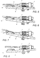
- the boundary layer becomes thinner and loses energy, until at a certain critical angle of incidence ⁇ C it breaks up, creating a vortex downstream and allowing the separation of the fluid column from the curved main surface 11, as shown schematically in Figure 7. It has been observed that for a deflector of the type shown in Figures 2, 3 and 4, the critical angle of incidence ⁇ C lies between 6° and 16° and is preferably close to 12°.
- This redirecting part comprises at least one curved channel 16 which is formed in the deflector 10.
- a channel 16 can be formed in the interspace between the end plate 9 of the arm and the lower face 13 of the laminar part 12, which is spaced and slightly inclined with respect to the plate 9 by an angle ⁇ that measures between 0° and 10° and is preferably close to 5°.
- the channel is laterally delimited by a curved redirection wall 17 which lies substantially at right angles to the part 12.
- the presence of a second side wall 17' that is substantially parallel to the first one 17 is optional, since it is not normally affected by the jet.
- the initial portion 18 of the wall 17 is substantially parallel to the longitudinal direction of the arm and is thus aligned with the axis g of the jet, whereas the final portion 19 is reorientated laterally with respect to the inlet portion.
- the lateral redirection angle measures between 20° and 50° and is preferably close to 35°.
- the redirection applied to the jet after passing through the channel 16 applies a tangential torque to the arm, and this torque is transferred to the spout 3 through the oscillation axis h .
- redirection channels 16 and 20 which are substantially symmetrical with respect to the centerline of the arm.
- the respective leading edges 14' and 14'' have a V-shaped arrangement with an internal angle that measures between 60° and 180° and is preferably close to 100°.
- a deflector 100 is mounted on the arm 8 and comprises an actuation part 101 that is shaped like a wing section with curved surfaces 102 and 103 and a substantially straight leading edge 104.
- the curved upper surface 102 corresponds to the main surface 11 and the lower surface 103 corresponds to the lower face 13 of the part 12 shown in Figures 1 to 4.
- the surfaces 102 and 103 are arranged symmetrically with respect to a plane referenced by S in Figure 10 which is substantially parallel to the pivoting axis h of the oscillating arm 8 and forms an angle of incidence ⁇ with respect to the axis g of the jet G in order to avoid instability of the actuator during startup and give the arm 8 an initial upward or downward thrust.
- the part 101 is arranged so that when the arm 8 is in the idle or initial condition, the jet skims tangentially over the surface 102 or 103 and forms a relatively small angle ⁇ with respect to the plane of symmetry S.
- the edge 104 of the part 101 can be sharp.
- the leading edge 104 of the part 101 is formed by two secondary surfaces 105, 105' which are formed respectively on the surfaces 102 and 103 and are inclined at a relatively large angle ⁇ with respect to the plane of symmetry S.
- the boundary layer breaks up and the negative pressure force produced by fluid dynamics that acts on the face 102 drops sharply, causing a sudden reversal of the forces produced by fluid dynamics that act on the part 101.
- the part 101 is drawn upward, that is to say, towards the axis of the jet, due to the negative pressure on the surface 102, until it reaches the tilt ⁇ c of its plane of symmetry S, and is then pushed down due to the thrust on the surface 102. In this way, oscillation begins in any operating condition with a gradually increasing breadth.
- the actuator part 101 is fixed to a substantially U-shaped bracket 106, particularly toward the end of its parallel sides 107 and 108 which are mutually connected by a transverse wall 109.
- the bracket 106 is in turn rigidly anchored to the side bars 8', 8'' of the oscillating arm 8.
- a redirecting part 110 is fixed between the sides 107 and 108 of the bracket 106, proximate to the transverse wall 109.
- This part comprises an anchoring plate 111 which is substantially flat and rectangular and to which a redirecting plate 112 is fixed; the plate 112 is thicker and narrower than the upper one, and has curved lateral walls 113 and 114 which are approximately symmetrical with respect to a plane T that is substantially parallel to the longitudinal axis g of the spout 3 and lies at right angles to the plane of symmetry S.
- the plate 111 is tilted and convergent along the direction of the stream with respect to the plane of symmetry S of the part 101, so as to form an angle ⁇ with respect to the part 101. In order to vary this angle, it is possible to provide two adjustment screws 115 and 116 arranged along the longitudinal plane T so as to rotate the plate 111 about the pivoting axis formed by the screws 117 and 118.
- the redirecting walls 113 and 114 form, together with the upper plate 111, two lateral channels which are suitable to redirect the jet laterally with respect to the longitudinal axis g of the nozzle 7, promoting the stepwise rotation of the spout 3.
- the tilt of the arm 8 with respect to the spout 3 one redirecting channel at a time is exposed, causing the rotation of the spout 3 about the second axis v in one direction or the other.
- the lower face 120 of the plate 112 which is struck by the jet when the deflector 110 moves downward during oscillation so as to give the deflector 100 an upward thrust, can be flat, with a central recess 121 which is inclined by an angle ⁇ with respect to the angle of the plate 111, so as to reduce the interference of the jet during the downward motion of the deflector. In this way, the amount of energy drawn from the jet for lateral redirection is substantially unchanged as the diameter and pressure of the jet increase.
- the lower face of the plate 112 can be shaped with two symmetrical surfaces which are inclined at an angle ⁇ which is equal to approximately 15°, as shown by the dashed line in Figure 12, eliminating the central recess 121.
- the actuator part 101 of the deflector 100 is meant to trigger and maintain in a steady state the oscillating motion of the arm 8 about its axis h
- the redirecting part 110 is meant to apply a stepwise rotary motion to the spout with respect to the second substantially vertical rotation axis v , so as to cover a circular region to be sprinkled.
- the jet actuator according to the invention is particularly effective and reliable even with small-diameter jets and at relatively low pressures, and can also be applied to small sprinklers.
- the materials, the shapes and the dimensions may be any according to the requirements.
Landscapes
- Nozzles (AREA)
- Fire-Extinguishing By Fire Departments, And Fire-Extinguishing Equipment And Control Thereof (AREA)
- Fluid-Pressure Circuits (AREA)
- Servomotors (AREA)
Claims (23)
- Strahlsteller, insbesondere zum Antreiben von hydraulischen Geräten wie drehenden Impulsregnern, der aufweist: eine Düse (7) zum Erzeugen eines freien Wasserstrahls (G), der entlang einer ersten Längsachse (g) ausgerichtet ist, wobei die Düse (7) an dem freien Ende eines Strahlrohrs (3) angeordnet ist, wobei das Strahlrohr mittels eines drehbaren Verbindungsstückes (5), das eine zweite Drehachse (v) hat, die quer zu der ersten Längsachse (g) ist, an eine Druckwasserleitung (6) angeschlossen ist; einen Ablenker (10; 100), der frei in eine Querrichtung zwischen einer ersten Endposition, in der er vollständig außerhalb des Strahls liegt, und einer zweiten Endposition, in der er bis zu einem maximalen Ausmaß in den Strahl eingetaucht ist, hin- und herschwingen kann, um einen Teil dessen Energie abzuziehen; eine Tragevorrichtung (8) zum hin- und herschwingbaren Anbringen des Ablenkers (10; 100) auf dem Strahlrohr (3), um die von dem Strahl abgezogene Energie auf das Strahlrohr (3) zu übertragen, um dessen schrittweise Bewegung um die zweite Drehachse (v) anzutreiben; dadurch gekennzeichnet, daß der Ablenker (10; 100) zumindest eine Hauptfläche (11; 102) mit einer gebogenen und konvexen Form hat, die geeignet ist, seitlich in den Strahl einzutreten, während sie im wesentlichen mit dem Strom ausgerichtet bleibt, um eine Unterdruckkraft zu erzeugen, die dazu führt, den Ablenker (10; 100) über ein anfängliches Hin- und Herschwingen und während des dauerhaften Hin- und Herschwingvorgangs in das Innere des Strahls zu bewegen, und er eine zweite Fläche (14; 105) hat, die im wesentlichen flach ist und bezüglich der gebogenen Hauptfläche (11; 102) einen Raumwinkel (β) bildet, der relativ groß ist, um eine Reaktionskraft mit einer Komponente zu erzeugen, die der auf der gebogenen Hauptfläche (10; 102) erzeugten Unterdruckkraft entgegengesetzt ist, und die dazu führt den Ablenker (10; 100) von dem Strahl weg zu drücken, wodurch somit das Hin- und Herschwingen im Dauerzustand begonnen und beibehalten wird.
- Strahlsteller gemäß Anspruch 1, dadurch gekennzeichnet, daß die gebogene Hauptfläche (11; 102) näherungsweise zylindrisch mit einem relativ weiten und konstanten Krümmungsradius (R) und mit einer Achse, die im wesentlichen in rechten Winkeln zu der Achse des Strahls liegt, ist.
- Strahlsteller gemäß Anspruch 2, dadurch gekennzeichnet, daß der Querschnitt der gebogenen Hauptfläche (11; 102) ein Profil hat, das im wesentlichen wie ein kreisförmiger Bogen geformt ist, in dem eine Bogensehne (d) oder respektiv eine Bezugsebene (S) einen durchschnittlichen Einfallswinkel (α) bezüglich der Achse (g) des Strahls (G) bildet.
- Strahlsteller gemäß Anspruch 3, dadurch gekennzeichnet, daß die gebogene Hauptfläche (11; 102) ein solches Profil hat, das sie im wesentlichen den Strom tangiert, wenn der Ablenker (10; 100) genau an dem Strahl entlang streicht.
- Strahlsteller gemäß Anspruch 3, dadurch gekennzeichnet, daß die Bogensehne (d) bzw. die Symmetrieebene (S) der gebogenen Hauptfläche (11; 102) so ausgerichtet ist, daß sie während des Eintauchens in den Strahl einen Einfallswinkel (α) bildet, der während jedes Hin- und Herschwingens schrittweise größer wird.
- Strahlsteller gemäß Anspruch 3, dadurch gekennzeichnet, daß der Einfallswinkel (α) einen kritischen Wert (αc) hat, der dafür eingerichtet ist, eine Trennung und ein vollständiges Aufbrechen der Flüssigkeitssäule oberhalb der Hauptfläche (11; 102) und einen plötzlichen Abfall in der auf diese ausgeübten Unterdruckkraft mit einer scharfen Umkehr der sich ergebenden Kraft, die auf den Ablenker (10; 100) einwirkt, zu bewirken.
- Strahlsteller gemäß Anspruch 6, dadurch gekennzeichnet, daß der kritische Einfallswinkel (αc) zwischen 6° und 16° liegt und vorzugsweise nahe 12°C ist.
- Strahlsteller gemäß Anspruch 1, dadurch gekennzeichnet, daß der Raumwinkel (β) zwischen 60° und 85° liegt und vorzugsweise nahe 75° ist.
- Strahlsteller gemäß Anspruch 1, dadurch gekennzeichnet, daß die querliegende Drehachse (v) im wesentlichen vertikal ist.
- Strahlsteller gemäß Anspruch 9, dadurch gekennzeichnet, daß eine Vorrichtung zum Abbremsen der Drehung des Strahlrohrs (3) um die vertikale Achse (v) bereitgestellt ist.
- Strahlsteller gemäß Anspruch 1, dadurch gekennzeichnet, daß die Vorrichtung (8) zum Tragen des Ablenkers (10; 100) einen im wesentlichen steifen Arm (8, 8', 8'') aufweist, der schwenkbar auf dem Strahlrohr (3) zum Hin- und Herschwingen um eine dritte Schwingachse (h), die im wesentlichen horizontal ist, angebracht ist.
- Strahlsteller gemäß Anspruch 1, dadurch gekennzeichnet, daß der Ablenker (10; 100) ein Stellteil (12; 101) mit einer relativ dünnen Wand aufweist, das eine obere Fläche (11; 102), die wie die gebogene Hauptfläche geformt ist, eine im wesentlichen flache oder respektiv gebogene untere Fläche (13; 103) und eine querliegende Vorderkante (14, 14', 14''; 105), die wie die flache zweite Fläche geformt ist, hat.
- Strahlsteller gemäß Anspruch 12, dadurch gekennzeichnet, daß das Stellteil (12) an einer im wesentlichen flachen Endplatte (9) verankert ist, die fest mit dem Arm (8) verbunden ist, wobei die untere Fläche (13) mit geringem räumlichen Abstand von der Endplatte (9) angeordnet und in bezug zu ihr leicht um einen Winkel (γ), der zwischen 0° und 10° liegt und vorzugsweise nahe 5° ist, geneigt ist.
- Strahlsteller gemäß Anspruch 12, dadurch gekennzeichnet, daß der Ablenker (10) eine Umlenkvorrichtung (16, 20; 112, 113, 114) hat, die geeignet ist, die seitliche Umlenkung des Strahls mit einer resultierenden tangentialen Reaktionskraft zu bewirken, um die Drehung des Strahlrohrs (3) um die zweite im wesentlichen vertikale Achse (v) anzutreiben.
- Strahlsteller gemäß Anspruch 14, dadurch gekennzeichnet, daß das Umlenkteil (16, 20) zumindest einen gebogenen Kanal (16), der zwischen der Endplatte (9) des Arms liegt, das Stellteil (12) und zumindest eine gebogene Umlenkwand (17) aufweist, die im wesentlichen senkrecht zu dem Teil (12) ist, wobei die Umlenkwand einen Eingangsbereich (18), der im wesentlichen parallel zu der Längsrichtung des Arms liegt, und einen Endbereich (19), der seitlich bezüglich des Einlaßbereiches ausgerichtet ist, hat.
- Strahlsteller gemäß Anspruch 15, dadurch gekennzeichnet, daß er zwei Umlenkkanäle (16, 20) aufweist, die bezüglich der Mittellinie des Arms (8) anstoßend und im wesentlichen symmetrisch sind, und die selektiv mit dem Strahl ausgerichtet werden können, um die Bewegung des Strahlrohrs in eine der beiden Drehrichtungen anzutreiben.
- Strahlsteller gemäß Anspruch 16, dadurch gekennzeichnet, daß die Vorderkante (14', 14'') des lamellenartigen Teils an den beiden Umlenkkanälen eine V-artige Grundrißform mit einem Innenwinkel hat, der zwischen 60° und 180° liegt und vorzugsweise nahe 100° ist.
- Strahlsteller gemäß Anspruch 12, dadurch gekennzeichnet, daß das Stellteil (101) im wesentlichen wie ein Flügelabschnitt mit oberen und unteren Flächen (102, 103) geformt ist, die im wesentlichen symmetrisch bezüglich einer Symmetrieebene (S) liegen, die einen veränderlichen Einfallswinkel (α) bezüglich der Achse des Strahls (g) und mit einer die zweite Fläche bildenden Vorderkante (105) bildet.
- Strahlsteller gemäß Anspruch 18, dadurch gekennzeichnet, daß er ein Umlenkteil (110) aufweist, das eine im wesentlichen flache Verankerungsplatte (111) aufweist, unter der eine Umlenkplatte (112) befestigt ist, wobei die Umlenkplatte zumindest eine gebogene Seitenumlenkfläche (113, 114) hat, die zumindest einen Umlenkkanal mit der Verankerungsplatte (111) bildet
- Strahlsteller gemäß Anspruch 19, dadurch gekennzeichnet, daß das Stellteil (101) und das Umlenkteil (110) in einer Position zwischen den Seitenarmen (107, 108) eines im wesentlichen U-förmigen Trägers (106) gehalten werden, der wiederum an dem Ende des Arms (8, 8', 8'') verankert ist.
- Strahlsteller gemäß Anspruch 15 oder 20, dadurch gekennzeichnet, daß der seitliche Umlenkwinkel (δ) der gebogenen Umlenkfläche (17; 113, 114) zwischen 20° und 50° mißt und vorzugsweise nahe 35° ist.
- Strahlsteller gemäß Anspruch 6, dadurch gekennzeichnet, daß er eine Vorrichtung (15; 115, 116) zum Einstellen der Position und der Einfallswinkel der Hauptfläche und der zweiten Fläche bezüglich der Achse des Strahls in der kritischen Einfallsposition aufweist.
- Strahlsteller gemäß Anspruch 1, dadurch gekennzeichnet, daß er Bremsvorrichtungen aufweist, die mit einer Kupplung (109) verbunden sind, um die Drehung des Strahlrohrs um die vertikale Achse abzubremsen, wobei die Bremsvorrichtungen selektiv in eine Richtung wirkend sind.
Applications Claiming Priority (3)
| Application Number | Priority Date | Filing Date | Title |
|---|---|---|---|
| ITVI940069 | 1994-05-12 | ||
| IT94VI000069A ITVI940069A1 (it) | 1994-05-12 | 1994-05-12 | Azionatore a getto, particolarmente per irrigatori ad impulso. |
| PCT/EP1995/000278 WO1995031288A1 (en) | 1994-05-12 | 1995-01-26 | Jet actuator particularly for pulse sprinklers |
Publications (2)
| Publication Number | Publication Date |
|---|---|
| EP0758926A1 EP0758926A1 (de) | 1997-02-26 |
| EP0758926B1 true EP0758926B1 (de) | 1998-04-01 |
Family
ID=11425514
Family Applications (1)
| Application Number | Title | Priority Date | Filing Date |
|---|---|---|---|
| EP95906991A Expired - Lifetime EP0758926B1 (de) | 1994-05-12 | 1995-01-26 | Strahlaktuator insbesondere für schrittweise drehende regner |
Country Status (13)
| Country | Link |
|---|---|
| US (1) | US5749523A (de) |
| EP (1) | EP0758926B1 (de) |
| CN (1) | CN1064866C (de) |
| AT (1) | ATE164534T1 (de) |
| AU (1) | AU692827B2 (de) |
| BR (1) | BR9507632A (de) |
| CA (1) | CA2189795A1 (de) |
| DE (1) | DE69501954T2 (de) |
| DK (1) | DK0758926T3 (de) |
| ES (1) | ES2114306T3 (de) |
| GR (1) | GR3026664T3 (de) |
| IT (1) | ITVI940069A1 (de) |
| WO (1) | WO1995031288A1 (de) |
Families Citing this family (4)
| Publication number | Priority date | Publication date | Assignee | Title |
|---|---|---|---|---|
| ITVI20060346A1 (it) | 2006-12-01 | 2008-06-02 | Komet Standard S R L | Irrigatore a scomparsa a lunga gittata |
| US7798428B1 (en) * | 2006-12-28 | 2010-09-21 | K-O-K, Llc | High pressure spray cleaning head and distributor body |
| US9682386B2 (en) | 2014-07-18 | 2017-06-20 | NaanDanJain Irrigation Ltd. | Irrigation sprinkler |
| US10232388B2 (en) | 2017-03-08 | 2019-03-19 | NaanDanJain Irrigation Ltd. | Multiple orientation rotatable sprinkler |
Family Cites Families (8)
| Publication number | Priority date | Publication date | Assignee | Title |
|---|---|---|---|---|
| US3580507A (en) * | 1969-06-09 | 1971-05-25 | Rain Bird Sprinkler Mfg | Drive mechanism for large volume rotary sprinklers |
| US3744720A (en) * | 1972-03-28 | 1973-07-10 | Nelson Irrigation Corp | Sprinkler head with improved brake and bearing assembly |
| AT342354B (de) * | 1976-04-09 | 1978-03-28 | Bauer Roehren Pumpen | Sektorregner mit strahlrohr und rucklaufpendel |
| US4153202A (en) * | 1977-10-19 | 1979-05-08 | Nelson Irrigation Corporation | Part-circle sprinkler head with improved quick-return mechanism |
| IT1172808B (it) * | 1983-03-18 | 1987-06-18 | Arno Drechsel | Deflettore universale di avanzamento per irrigatori a impatto |
| US4669663A (en) * | 1985-04-23 | 1987-06-02 | Nelson Irrigation Company | Large volume sprinkler head with part-circle step by step movements in both directions |
| SU1535468A1 (ru) * | 1988-01-18 | 1990-01-15 | Научно-Производственное Объединение По Сельскохозяйственному Машиностроению "Висхом" | Дождевальный аппарат |
| AU655029B2 (en) * | 1992-06-09 | 1994-12-01 | Carl Leopold Clarence Kah Jr. | Adjustable arc spray and rotary stream sprinkler |
-
1994
- 1994-05-12 IT IT94VI000069A patent/ITVI940069A1/it unknown
-
1995
- 1995-01-26 DE DE69501954T patent/DE69501954T2/de not_active Expired - Lifetime
- 1995-01-26 AU AU15364/95A patent/AU692827B2/en not_active Expired
- 1995-01-26 CN CN951930338A patent/CN1064866C/zh not_active Expired - Lifetime
- 1995-01-26 AT AT95906991T patent/ATE164534T1/de active
- 1995-01-26 US US08/732,280 patent/US5749523A/en not_active Expired - Lifetime
- 1995-01-26 DK DK95906991.5T patent/DK0758926T3/da active
- 1995-01-26 EP EP95906991A patent/EP0758926B1/de not_active Expired - Lifetime
- 1995-01-26 WO PCT/EP1995/000278 patent/WO1995031288A1/en not_active Ceased
- 1995-01-26 BR BR9507632A patent/BR9507632A/pt not_active IP Right Cessation
- 1995-01-26 CA CA002189795A patent/CA2189795A1/en not_active Abandoned
- 1995-01-26 ES ES95906991T patent/ES2114306T3/es not_active Expired - Lifetime
-
1998
- 1998-04-15 GR GR980400869T patent/GR3026664T3/el unknown
Also Published As
| Publication number | Publication date |
|---|---|
| BR9507632A (pt) | 1997-09-23 |
| ITVI940069A1 (it) | 1995-11-12 |
| AU1536495A (en) | 1995-12-05 |
| WO1995031288A1 (en) | 1995-11-23 |
| CN1064866C (zh) | 2001-04-25 |
| ES2114306T3 (es) | 1998-05-16 |
| CN1147775A (zh) | 1997-04-16 |
| DE69501954T2 (de) | 1998-07-30 |
| CA2189795A1 (en) | 1995-11-23 |
| MX9605509A (es) | 1998-05-31 |
| DK0758926T3 (da) | 1998-06-02 |
| DE69501954D1 (de) | 1998-05-07 |
| US5749523A (en) | 1998-05-12 |
| AU692827B2 (en) | 1998-06-18 |
| EP0758926A1 (de) | 1997-02-26 |
| ATE164534T1 (de) | 1998-04-15 |
| ITVI940069A0 (it) | 1994-05-12 |
| GR3026664T3 (en) | 1998-07-31 |
Similar Documents
| Publication | Publication Date | Title |
|---|---|---|
| US6360965B1 (en) | Fluid delivery from a spray head having a moving nozzle | |
| US4253608A (en) | Part-circle sprinkler with reversible stator | |
| SK393092A3 (en) | Rotating percussion sprinkler | |
| EP1104332B1 (de) | Taumelnde austragvorrichtung für fluide | |
| US6199771B1 (en) | Single chamber spray head with moving nozzle | |
| US6254013B1 (en) | Spray head for use with low pressure fluid sources | |
| US5328097A (en) | Rotor nozzle for a high-pressure cleaning device | |
| CA1316516C (en) | Aerofoil/hydrofoil | |
| US6092739A (en) | Spray head with moving nozzle | |
| JPH0253108B2 (de) | ||
| AU692827B2 (en) | Jet actuator particularly for pulse sprinklers | |
| US4164324A (en) | Sprinkler head with improved integral impact arm and anti-backsplash drive spoon | |
| IL76072A (en) | Drive arm deflector for a rotary impact sprinkler | |
| US4595141A (en) | Drive nozzle assembly for a reaction drive sprinkler | |
| GB2075866A (en) | Shower fitting | |
| JPH05209427A (ja) | 板状水流蛇口 | |
| US4496103A (en) | Reaction drive sprinkler | |
| US6502434B1 (en) | Effluent shower for pulp washer | |
| US7216817B2 (en) | Impact sprinkler drive system | |
| US5622316A (en) | Self-adjusting jet breaker for impact sprinklers | |
| US4457470A (en) | Impulse sprinkler | |
| EP0044661B1 (de) | Verfahren und Vorrichtung zum Beschichten einer Bahn | |
| MXPA96005509A (en) | Jet actuator particularly for pulse sprinklers | |
| CN114570538A (zh) | 用于方向可变的喷淋头射束的喷淋头射束产生装置 | |
| US4205787A (en) | Sprinkler head with an improved slotted drive spoon |
Legal Events
| Date | Code | Title | Description |
|---|---|---|---|
| PUAI | Public reference made under article 153(3) epc to a published international application that has entered the european phase |
Free format text: ORIGINAL CODE: 0009012 |
|
| 17P | Request for examination filed |
Effective date: 19961119 |
|
| AK | Designated contracting states |
Kind code of ref document: A1 Designated state(s): AT DE DK ES FR GB GR IT NL PT |
|
| GRAG | Despatch of communication of intention to grant |
Free format text: ORIGINAL CODE: EPIDOS AGRA |
|
| 17Q | First examination report despatched |
Effective date: 19970604 |
|
| GRAG | Despatch of communication of intention to grant |
Free format text: ORIGINAL CODE: EPIDOS AGRA |
|
| GRAH | Despatch of communication of intention to grant a patent |
Free format text: ORIGINAL CODE: EPIDOS IGRA |
|
| GRAH | Despatch of communication of intention to grant a patent |
Free format text: ORIGINAL CODE: EPIDOS IGRA |
|
| GRAA | (expected) grant |
Free format text: ORIGINAL CODE: 0009210 |
|
| AK | Designated contracting states |
Kind code of ref document: B1 Designated state(s): AT DE DK ES FR GB GR IT NL PT |
|
| REF | Corresponds to: |
Ref document number: 164534 Country of ref document: AT Date of ref document: 19980415 Kind code of ref document: T |
|
| REF | Corresponds to: |
Ref document number: 69501954 Country of ref document: DE Date of ref document: 19980507 |
|
| REG | Reference to a national code |
Ref country code: ES Ref legal event code: FG2A Ref document number: 2114306 Country of ref document: ES Kind code of ref document: T3 |
|
| REG | Reference to a national code |
Ref country code: DK Ref legal event code: T3 |
|
| ITF | It: translation for a ep patent filed | ||
| ET | Fr: translation filed | ||
| REG | Reference to a national code |
Ref country code: PT Ref legal event code: SC4A Free format text: AVAILABILITY OF NATIONAL TRANSLATION Effective date: 19980420 |
|
| PLBE | No opposition filed within time limit |
Free format text: ORIGINAL CODE: 0009261 |
|
| STAA | Information on the status of an ep patent application or granted ep patent |
Free format text: STATUS: NO OPPOSITION FILED WITHIN TIME LIMIT |
|
| 26N | No opposition filed | ||
| REG | Reference to a national code |
Ref country code: GB Ref legal event code: IF02 |
|
| REG | Reference to a national code |
Ref country code: PT Ref legal event code: MM4A Free format text: LAPSE DUE TO NON-PAYMENT OF FEES Effective date: 20100726 |
|
| PG25 | Lapsed in a contracting state [announced via postgrant information from national office to epo] |
Ref country code: PT Free format text: LAPSE BECAUSE OF NON-PAYMENT OF DUE FEES Effective date: 20100726 |
|
| REG | Reference to a national code |
Ref country code: PT Ref legal event code: NF4A Free format text: RESTITUTIO IN INTEGRUM Effective date: 20110127 |
|
| PGRI | Patent reinstated in contracting state [announced from national office to epo] |
Ref country code: PT Effective date: 20110127 |
|
| PGFP | Annual fee paid to national office [announced via postgrant information from national office to epo] |
Ref country code: NL Payment date: 20130122 Year of fee payment: 19 Ref country code: GR Payment date: 20130130 Year of fee payment: 19 |
|
| PGFP | Annual fee paid to national office [announced via postgrant information from national office to epo] |
Ref country code: DE Payment date: 20140211 Year of fee payment: 20 Ref country code: DK Payment date: 20140122 Year of fee payment: 20 |
|
| PGFP | Annual fee paid to national office [announced via postgrant information from national office to epo] |
Ref country code: AT Payment date: 20140121 Year of fee payment: 20 Ref country code: IT Payment date: 20140129 Year of fee payment: 20 Ref country code: ES Payment date: 20140220 Year of fee payment: 20 Ref country code: FR Payment date: 20140123 Year of fee payment: 20 |
|
| PGFP | Annual fee paid to national office [announced via postgrant information from national office to epo] |
Ref country code: GB Payment date: 20140205 Year of fee payment: 20 Ref country code: PT Payment date: 20140115 Year of fee payment: 20 |
|
| REG | Reference to a national code |
Ref country code: NL Ref legal event code: V1 Effective date: 20140801 |
|
| REG | Reference to a national code |
Ref country code: GR Ref legal event code: ML Ref document number: 980400869 Country of ref document: GR Effective date: 20140801 |
|
| PG25 | Lapsed in a contracting state [announced via postgrant information from national office to epo] |
Ref country code: NL Free format text: LAPSE BECAUSE OF NON-PAYMENT OF DUE FEES Effective date: 20140801 Ref country code: GR Free format text: LAPSE BECAUSE OF NON-PAYMENT OF DUE FEES Effective date: 20140801 |
|
| REG | Reference to a national code |
Ref country code: DE Ref legal event code: R071 Ref document number: 69501954 Country of ref document: DE |
|
| REG | Reference to a national code |
Ref country code: DK Ref legal event code: EUP Effective date: 20150126 |
|
| REG | Reference to a national code |
Ref country code: PT Ref legal event code: MM4A Free format text: MAXIMUM VALIDITY LIMIT REACHED Effective date: 20150126 |
|
| REG | Reference to a national code |
Ref country code: GB Ref legal event code: PE20 Expiry date: 20150125 |
|
| REG | Reference to a national code |
Ref country code: AT Ref legal event code: MK07 Ref document number: 164534 Country of ref document: AT Kind code of ref document: T Effective date: 20150126 |
|
| PG25 | Lapsed in a contracting state [announced via postgrant information from national office to epo] |
Ref country code: PT Free format text: LAPSE BECAUSE OF EXPIRATION OF PROTECTION Effective date: 20150203 |
|
| PG25 | Lapsed in a contracting state [announced via postgrant information from national office to epo] |
Ref country code: GB Free format text: LAPSE BECAUSE OF EXPIRATION OF PROTECTION Effective date: 20150125 |
|
| REG | Reference to a national code |
Ref country code: ES Ref legal event code: FD2A Effective date: 20150826 |
|
| PG25 | Lapsed in a contracting state [announced via postgrant information from national office to epo] |
Ref country code: ES Free format text: LAPSE BECAUSE OF EXPIRATION OF PROTECTION Effective date: 20150127 |