EP0758525B1 - Tropfbewässerungsauslass - Google Patents
Tropfbewässerungsauslass Download PDFInfo
- Publication number
- EP0758525B1 EP0758525B1 EP96112818A EP96112818A EP0758525B1 EP 0758525 B1 EP0758525 B1 EP 0758525B1 EP 96112818 A EP96112818 A EP 96112818A EP 96112818 A EP96112818 A EP 96112818A EP 0758525 B1 EP0758525 B1 EP 0758525B1
- Authority
- EP
- European Patent Office
- Prior art keywords
- emitter
- conduit line
- groove
- membrane
- pressure
- Prior art date
- Legal status (The legal status is an assumption and is not a legal conclusion. Google has not performed a legal analysis and makes no representation as to the accuracy of the status listed.)
- Expired - Lifetime
Links
- 230000002262 irrigation Effects 0.000 title claims description 40
- 238000003973 irrigation Methods 0.000 title claims description 40
- 239000012528 membrane Substances 0.000 claims description 52
- 239000012530 fluid Substances 0.000 claims description 48
- 210000003027 ear inner Anatomy 0.000 claims description 7
- 238000011010 flushing procedure Methods 0.000 claims description 5
- 239000000463 material Substances 0.000 claims description 4
- XLYOFNOQVPJJNP-UHFFFAOYSA-N water Substances O XLYOFNOQVPJJNP-UHFFFAOYSA-N 0.000 description 3
- 238000005452 bending Methods 0.000 description 2
- 239000000654 additive Substances 0.000 description 1
- 239000003337 fertilizer Substances 0.000 description 1
- 238000000034 method Methods 0.000 description 1
- 235000015097 nutrients Nutrition 0.000 description 1
- 239000002245 particle Substances 0.000 description 1
- 239000007779 soft material Substances 0.000 description 1
- 239000007921 spray Substances 0.000 description 1
Images



Classifications
-
- A—HUMAN NECESSITIES
- A01—AGRICULTURE; FORESTRY; ANIMAL HUSBANDRY; HUNTING; TRAPPING; FISHING
- A01G—HORTICULTURE; CULTIVATION OF VEGETABLES, FLOWERS, RICE, FRUIT, VINES, HOPS OR SEAWEED; FORESTRY; WATERING
- A01G25/00—Watering gardens, fields, sports grounds or the like
- A01G25/02—Watering arrangements located above the soil which make use of perforated pipe-lines or pipe-lines with dispensing fittings, e.g. for drip irrigation
- A01G25/023—Dispensing fittings for drip irrigation, e.g. drippers
-
- Y—GENERAL TAGGING OF NEW TECHNOLOGICAL DEVELOPMENTS; GENERAL TAGGING OF CROSS-SECTIONAL TECHNOLOGIES SPANNING OVER SEVERAL SECTIONS OF THE IPC; TECHNICAL SUBJECTS COVERED BY FORMER USPC CROSS-REFERENCE ART COLLECTIONS [XRACs] AND DIGESTS
- Y02—TECHNOLOGIES OR APPLICATIONS FOR MITIGATION OR ADAPTATION AGAINST CLIMATE CHANGE
- Y02A—TECHNOLOGIES FOR ADAPTATION TO CLIMATE CHANGE
- Y02A40/00—Adaptation technologies in agriculture, forestry, livestock or agroalimentary production
- Y02A40/10—Adaptation technologies in agriculture, forestry, livestock or agroalimentary production in agriculture
- Y02A40/22—Improving land use; Improving water use or availability; Controlling erosion
Definitions
- the present invention relates to drip irrigation, and in particular to a pressure controlled drip irrigation emitter and apparatus capable of maintaining a constant drip rate over a very wide range of pressure.
- drip irrigation emitters are associated in some way with a conduit line through which a pressurized fluid may flow.
- the fluid can be anything, but is typically water for growing plants, either by itself or with dissolved additives such as fertilizers or nutrients.
- Drip irrigation emitters may be attached to the end of a conduit line, attached along the outside of a conduit line, or inserted into the inside of a conduit line where there is a tiny hole that allows fluid to reach the outside. In every drip irrigation emitter, there is some means for allowing fluid inside the line to reach the outside at a very slow rate.
- Very high pressure is usually required at the beginning of a conduit line in order to assure that at least some pressure reaches all of the line.
- the longer the line the greater the initial pressure required.
- lower locations on the line will naturally have higher pressure than higher locations.
- emitters Because of the way currently developed emitters are designed, they are not useful in lines where high pressure will be used (e.g. near the beginning of the line, or at a low spot) because at such pressures they tend to reduce the flow rate or close off completely. It is therefore desirable to have a drip irrigation emitter that not only operates at relatively low pressures, but which has a constant flow rate through a wide range of pressures, including very high pressures, without the flow rate dropping or the emitter shutting off completely.
- the present invention postpones the shut off problems associated with high pressure in drip irrigation lines by providing a small drip irrigation emitter that is capable of providing a constant flow rate over a wide range of low and high fluid line pressures.
- the present invention provides a small drip irrigation emitter that can be used with a small or large diameter line. The emitter may be placed inside or attached to the outside of the line.
- the emitter has a small relatively soft flat flexible membrane inside, suspended around its perimeter on a platform having a central cavity therein.
- the membrane covers the cavity and is able to be bent into it.
- One side of the membrane is in contact with the main fluid flow and pressure of the drip irrigation line, and the other side is exposed to lower-pressure fluid which has traveled through a series of labyrinths and turbulent flow passages.
- the membrane is suspended on a perimeter platform above the cavity which has a flat surface at the bottom.
- the bottom surface has an exit hole at or near the center, and an annular opening around its edges. The annular opening leads back to the fluid in the line through a series of pressure-reducing labyrinths and turbulent flow paths located in the body of the emitter.
- a groove is provided on the bottom surface leading radially outward from the central exit hole to the annular opening at the edge of the bottom surface.
- a small open slot having a slightly rounded corner is provided in the hole where it meets the groove.
- the slot is generally parallel to the exit hole and perpendicular to the groove. The slot gives the hole the appearance of a keyhole when viewed from directly above.
- the opposite end of the groove at the edge of the surface communicates with the reduced-pressure fluid from the annular opening.
- the suspended membrane As pressure is provided in the conduit line, the suspended membrane is first pressed into the cavity against the bottom surface having the exit hole, groove and slot in it. This limits the amount of fluid that may escape, originating from the annular opening, traveling across the groove in the surface and out through the exit hole. As pressure increases, most of the exit hole (except for the slot) is closed by the membrane; however, even after much of the exit hole is closed, the groove and keyhole slot allow a small, steady trickle of fluid to continue to escape. It requires an extremely high pressure in the fluid in the line to close both the hole and the slot of the present invention.
- the height of the cavity between the bottom surface and the perimeter support for the membrane is large enough to allow the initial flow of fluid into the emitter to wash out any dirt or debris before the membrane begins to bend downward and close off the exit hole.
- a relatively soft membrane is required in a small emitter in order to bend down into such a deep cavity.
- the height of the cavity relative to the larger surface of the membrane is less significant, allowing a harder membrane to be effectively used in larger emitters.
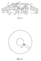
- Fig. 1 is an enlarged cross sectional side view of the preferred embodiment of the present invention showing detail of the area around the exit opening.
- Fig. 2 is a cross sectional end view along line 2--2 of Fig. 1.
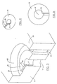
- Fig. 3 is a greatly enlarged perspective cut-away detail view of the interior of the drip irrigation emitter of the present invention showing the internal cavity without the membrane in the vicinity of the exit opening.
- Fig. 4 is a slightly enlarged fragmentary perspective view of the interior of the drip irrigation emitter of the present invention in the vicinity of the exit opening.
- Fig. 5 is a top plan view of the exit opening in the bottom surface of the internal cavity of the drip irrigation emitter of the present invention showing its keyhole appearance.
- Fig. 6 is an enlarged cross-sectional side view of the exit cavity of Fig. 1 showing the flexible membrane of the present invention suspended above the opening without any pressure applied to it.
- Fig. 7 is the enlarged cross-sectional side view of Fig. 6 showing the flexible membrane of the present invention bending as pressure is applied to it.
- Fig. 9 is an enlarged cross-sectional side view of the exit cavity of an alternative embodiment of Fig. 1 showing the flexible membrane of the present invention suspended above the opening without any pressure applied to it.
- Fig. 10 is a greatly enlarged perspective cut-away detail view of the interior of the alternative embodiment of Fig. 9 showing the internal cavity without the membrane in the vicinity of the exit opening. In this embodiment there is no vertical slot.
- Fig. 11 is the enlarged cross-sectional side view of Fig. 9 showing the flexible membrane in the alternative embodiment of the present invention bending as pressure is applied to it.
- Fig. 12 is a top plan view of the exit opening in the bottom surface of the internal cavity of the alternative embodiment of the drip irrigation emitter shown in Figs. 9 - 11.
- the invention includes a drip irrigation emitter, generally 10, inserted into a conduit line 9.
- the emitter includes a housing 11 with a central exit hole 12 therein. Hole 12 allows for fluid to pass from the inside of emitter 10 through a series of channels 26 to holes 27 in the conduit line 9 leading to the exterior (see Fig. 2). It is seen in Fig. 2 at dimension "A" that housing 11 has a low internal profile of less than three and one-half millimeters (3.5 mm) greater than the thickness of tube 10. This allows for less friction with the fluid in the line 9 resulting in less pressure loss from to the presence of the emitters 10 in the line.
- a central internal cavity 20 is provided above exit hole 12. At the bottom of cavity 20 is a flat surface 19 which surrounds hole 12. An opening 23 is provided around the perimeter of surface 19. Opening 23 leads back to the inside of the emitter through a series of labyrinths and turbulent flow paths 24 in emitter housing 11. These labyrinths and turbulent flow paths 24 lead back and forth across and around emitter 10 to reduce the pressure of fluid flowing therethrough, as is well known in the art.
- a shallow horizontal groove 15 is provided in surface 19 extending radially outward from exit hole 12 to perimeter opening 23 at the edge of surface 19.
- a slot 17 may be provided in exit hole 12 where it meets groove 15. Slot 17 is generally perpendicular to surface 19 and parallel to opening 12 and provides a gap 18 between the end of groove 15 and the edge of opening 12. The gap 18 of slot 17 increases the surface area of opening 12 as shown in the top view of Fig. 5.
- the inside corner 28 of slot 17 may be slightly rounded.
- a flexible membrane 21 is provided above cavity 20 and is suspended around its perimeter on a platform 29 as shown in Figs. 1, 2 and 6.
- the membrane 21 covers the opening and is able to be bent into it.
- the distance between surface 19 and platform 29 defines Cavity 20 and provides a gap below membrane 21 that is large enough to allow dirt and other potentially clogging debris particles to flush out through exit hole 12 at very low fluid pressure, such as when fluid is first introduced into or shut off from the emitter.
- membrane 21 is bent downward into cavity 20 as shown in Fig. 7 partially closing off exit 12 except for groove 15 and the gap 18 formed by slot 17. This causes the emitter 11 to drip at a constant but very small trickle of fluid is allowed to escape across groove 15 and slot 17 through exit hole 12.
- FIG. 9 An alternative embodiment is shown in Figs. 9, 10 and 11.
- slot 17 is omitted, and the inside edge 28 of groove 15 is rounded downward into opening 12 resulting in a gap above edge 28.
- This tapered inside edge 28 of groove 15 allows the emitter to operate in the same manner as described above without using slot 17.
- the alternative embodiment does not close off until a very high pressure of at least 620.53 kPa (ninety (90) psi) is reached. This is achieved because it takes a very high fluid pressure to press the membrane 21 firmly against the gap formed by the downwardly sloping edge 28 of groove 15. The deeper and more pronounced the slope of edge 28, the higher the pressure required to shut off the emitter.
- the emitter of the present invention is made of sturdy rigid material, such as plastic.
- the emitter is small enough to fit inside an irrigation line having a diameter of 1.27 cm (one-half inch (1/2")) or smaller, but can be of a larger size if desired.
- a small sized emitter is preferred because it provides a wide range of applications in smaller environments, while also performing exactly like a large emitter in larger environments.
- the cavity bottom and the membrane of the preferred small version of the emitter each have a correspondingly small surface area. Because of its small size, it is important that the membrane be made of a relatively soft material having a shore hardness of between 40 and 50 in order to allow it to bend more readily into the cavity under pressure from fluid in the line. Stiffer membranes should only be used in larger versions of the invention where the surface and cavity to be covered are larger, and more membrane surface area is available for the fluid to put pressure on.
- slot 17 is provided in the exit hole 12.
- the corner 28 of the groove 15 leading down to the slot should preferably be rounded downward into the exit hole, although this is not required.
- the slot facilitates a trickle of fluid flow at very high pressures by defining a gap between the end of the groove 15 and the exit opening 12.
- the preferred embodiment provides a cavity 20 having a distance of approximately one millimeter (1 mm) between surface 19 and platform 29 suspending the flexible membrane. This distance provides a sufficient gap to allow dirt and debris to be flushed out of the emitter at very low pressure thereby avoiding clogging.
- a soft membrane is required in the small versions of the invention in order to be sufficiently flexible to readily close this gap and make contact with surface 19.
- a larger emitter may be provided having a larger surface 19, a wider platform 29 and a stiffer membrane 21.
- a cavity 20 height of only 1 millimeter (1 mm) between surface 19 and platform 29 still provides a sufficient cavity for flushing out debris. Because of the larger areas of membrane 21 and surface 19 coupled with a cavity of approximately 1 mm in height, a less flexible membrane will still close the gap between platform 29 and surface 19.
- the emitter may be designed to attach to the outside of a conduit line, instead of inserted inside the line.
- a conduit line instead of inserted inside the line.
- Such an embodiment involves a self-contained unit that has an outward appearance of a shell as opposed to a cylinder.
- the relationships of the fluid flow to membrane 21, cavity 20, platform 29, surface 19, groove 15 and opening 12 within housing 11 are the same as with the insertable emitter; however, the labyrinths and turbulent flow paths are located inside the shell of the emitter.
- Changes and adjustments may be made in the size and/or shape of the laybrinths 24, cavity 20, groove 15, slot 17, opening 12, membrane 21, surface 19 and/or platform 29 in order to obtain a desired flow rate over a desired range of fluid pressures for a conduit line having a desired diameter.
Landscapes
- Life Sciences & Earth Sciences (AREA)
- Soil Sciences (AREA)
- Engineering & Computer Science (AREA)
- Water Supply & Treatment (AREA)
- Environmental Sciences (AREA)
- Nozzles (AREA)
- Infusion, Injection, And Reservoir Apparatuses (AREA)
Claims (17)
- Tropfenirrigations-Emissionseinrichtung (10) mit einem Gehäuse (11) zur Anbringung an einer Kanalleitung (9), wobei das genannte Gehäuse (11) eine flache innere Oberfläche (19) an der Unterseite einer Vertiefung (20) aufweist, mit einer flachen, flexiblen Membran (21), die an deren Perimeter biegbar von einer Plattform (29) oberhalb der Vertiefung (20) getragen wird, wobei die obere Seite dem Druck von Fluid ausgesetzt ist, das in der genannten Kanalleitung (9) fließt, mit einer zentralen Öffnung (12) in der genannten Oberfläche (19), die im rechten Winkel dazu ausgerichtet ist und nach außen führt, gekennzeichnet durch eine Rille (15) an der genannten Oberfläche (19), die sich von der genannten Öffnung (12) radial auswärts zu einer Kante der genannten Oberfläche (19) erstreckt, mit einer zweiten Öffnung (23) an der Kante der genannten Oberfläche (19), die durch eine Mehrzahl druckreduzierender Labyrinthe (24) zurück zu dem Fluidfluß in der genannten Kanalleitung (9) führt, und mit einem Schlitz (17) in der genannten zentralen Öffnung (12) an der Verbindungsstelle mit der genannten Rille (15), wobei bei einer Einführung von Druckfluid von der genannten Kanalleitung (9) in die genannte Emissionseinrichtung (10) die genannte Membran (21) in die genannte Vertiefung (20) drückt und gegen die Oberfläche (19), die Rille (15), den Schlitz (17) und die zentrale Öffnung (12), wodurch der Fluß von der Emissionseinrichtung (10) auf eine konstante Rate über einen Bereich von einem sehr niedrigen bis zu einem sehr hohen Druck begrenzt wird.
- Emissionseinrichtung (10) nach Anspruch 1, wobei der genannte Schlitz (17) senkrecht zu der genannten Rille (15) angeordnet ist, und wobei die Ecke (28) zwischen dem genannten Schlitz (17) und der genannten Rille (15) abgerundet ist.
- Emissionseinrichtung (10) nach Anspruch 1 oder 2, wobei die genannte Membran (21) aus einem verhältnismäßig weichen, biegbaren Werkstoff hergestellt wird.
- Emissionseinrichtung (10) nach einem der vorstehenden Ansprüche, wobei die genannte Emissionseinrichtung (10) klein genug ist, so daß sie in eine Kanalleitung (9) mit einem Durchmesser von nicht mehr als 1,27 cm (0,5 Inch) paßt.
- Emissionseinrichtung (10) nach einem der vorstehenden Ansprüche, wobei die genannte Emissionseinrichtung (10) in eine Kanalleitung (9) eingeführt wird.
- Emissionseinrichtung (10) nach einem der Ansprüche 1 bis 4, wobei die genannte Emissionseinrichtung (4) an der Außenseite einer Kanalleitung (9) angebracht ist.
- Emissionseinrichtung (10) nach einem der vorstehenden Ansprüche, wobei zwischen der genannten Oberfläche (19) und der genannten Plattform (29) ein Zwischenraum vorgesehen ist, um es zu ermöglichen, daß Rückstände mit niedrigem Anfangsfluiddruck aus dem Inneren der Emissionseinrichtung (10) gespült werden.
- Emissionseinrichtung (10) nach Anspruch 7, wobei der Abstand zwischen der genannten Plattform (29) und der genannten Oberfläche (19) ungefähr einen Millimeter beträgt.
- Emissionseinrichtung (10) nach einem der vorstehenden Ansprüche, wobei der Außendurchmesser der genannten Membran (21) nicht mehr als acht Millimeter (8 mm) beträgt.
- Emissionseinrichtung (10) nach einem der vorstehenden Ansprüche, wobei das genannte Gehäuse (11) eine flache Höhe von nicht mehr als dreieinhalb Millimetern (3,5 mm) aufweist.
- Tropfenirrigations-Emissionseinrichtung (10) mit einem Gehäuse (11) zur Anbringung an einer Kanalleitung (9), wobei das genannte Gehäuse (11) eine flache innere Oberfläche (19) an der Unterseite einer Vertiefung (20) aufweist, mit einer flachen, flexiblen Membran (21), die an deren Perimeter biegbar von einer Plattform (29) oberhalb der Vertiefung (20) getragen wird, wobei die obere Seite dem Druck von Fluid ausgesetzt ist, das in der genannten Kanalleitung (9) fließt, mit einer zentralen Öffnung (12) in der genannten Oberfläche (19), die im rechten Winkel dazu ausgerichtet ist und nach außen führt, gekennzeichnet durch eine Rille (15) an der genannten Oberfläche (19), die sich von der genannten Öffnung (12) radial auswärts zu einer Kante der genannten Oberfläche (19) erstreckt, wobei die genannte Rille (15) an der Stelle, an der sie auf die genannte Öffnung (12) trifft, eine abgerundete Ecke (28) aufweist, mit einer zweiten Öffnung (23) an der Kante der genannten Oberfläche (19), die durch eine Mehrzahl druckreduzierender Labyrinthe (24) zurück zu dem Fluidfluß in der genannten Kanalleitung (9) führt, wobei bei einer Einführung von Druckfluid von der genannten Kanalleitung (9) in die genannte Emissionseinrichtung (10) die genannte Membran (21) in die genannte Vertiefung (20) drückt und gegen die Oberfläche (19), die Rille (15), die abgerundete Ecke (28) und die zentrale Öffnung (12), wodurch der Fluß von der Emissionseinrichtung (10) auf eine konstante Rate über einen Bereich von einem sehr niedrigen bis zu einem sehr hohen Druck begrenzt wird.
- Emissionseinrichtung (10) nach Anspruch 11, wobei die genannte Membran (21) aus einem verhältnismäßig weichen, biegbaren Werkstoff hergestellt wird.
- Emissionseinrichtung (10) nach Anspruch 11 oder 12, wobei die genannte Emissionseinrichtung (10) in eine Kanalleitung (9) eingeführt wird.
- Emissionseinrichtung (10) nach einem der Ansprüche 11 bis 13, wobei die genannte Emissionseinrichtung (10) klein genug ist, so daß sie in eine Kanalleitung (9) mit einem Durchmesser von nicht mehr als 1,27 cm (0,5 Inch) paßt.
- Emissionseinrichtung (10) nach Anspruch 11 oder 12, wobei die genannte Emissionseinrichtung (10) an der Außenseite einer Kanalleitung angebracht ist.
- Emissionseinrichtung (10) nach einem der Ansprüche 11 bis 15, wobei zwischen der genannten Oberfläche (19) und der genannten Plattform (29) ein Zwischenraum vorgesehen ist, um es zu ermöglichen, daß Rückstände mit niedrigem Anfangsfluiddruck aus dem Inneren der Emissionseinrichtung (10) gespült werden.
- Emissionseinrichtung (10) nach Anspruch 16, wobei der Abstand zwischen der genannten Plattform (29) und der genannten Oberfläche (19) ungefähr einen Millimeter beträgt.
Applications Claiming Priority (2)
| Application Number | Priority Date | Filing Date | Title |
|---|---|---|---|
| US08/515,125 US5628462A (en) | 1995-08-15 | 1995-08-15 | Drip irrigation emitter |
| US515125 | 2000-02-28 |
Publications (2)
| Publication Number | Publication Date |
|---|---|
| EP0758525A1 EP0758525A1 (de) | 1997-02-19 |
| EP0758525B1 true EP0758525B1 (de) | 1998-11-25 |
Family
ID=24050071
Family Applications (1)
| Application Number | Title | Priority Date | Filing Date |
|---|---|---|---|
| EP96112818A Expired - Lifetime EP0758525B1 (de) | 1995-08-15 | 1996-08-08 | Tropfbewässerungsauslass |
Country Status (7)
| Country | Link |
|---|---|
| US (1) | US5628462A (de) |
| EP (1) | EP0758525B1 (de) |
| AU (1) | AU706816B2 (de) |
| ES (1) | ES2124614T3 (de) |
| GR (1) | GR3029307T3 (de) |
| IL (1) | IL119011A (de) |
| ZA (1) | ZA966829B (de) |
Families Citing this family (37)
| Publication number | Priority date | Publication date | Assignee | Title |
|---|---|---|---|---|
| IL117326A (en) * | 1996-03-01 | 1999-11-30 | Cohen Amir | Regulated flow-restrictor devices particularly useful in drip irrigation |
| IL122777A (en) * | 1997-12-28 | 2003-12-10 | Amir Cohen | Valve controlled drip irrigation lines |
| US6186423B1 (en) | 1999-10-18 | 2001-02-13 | John A. Chapman | Irrigation system |
| US6464152B1 (en) * | 2000-04-06 | 2002-10-15 | Eurodrip, S.A. | Self-cleaning pressure compensating irrigation drip emitter |
| ITSV20010012A1 (it) * | 2001-04-20 | 2002-10-20 | Irritec Srl | Emettitore autocompensante per irrigazione goccia a goccia |
| US6736337B2 (en) | 2002-02-08 | 2004-05-18 | The Toro Company | Pressure compensating drip irrigation hose |
| US6959882B1 (en) | 2002-06-14 | 2005-11-01 | Potts David A | Watering and aerating soil with a drip line |
| ES2223241B1 (es) * | 2002-10-02 | 2006-05-16 | Irrimon, S.A.U. | Emisor autocompensante de riego por goteo, con dispositivo de flujo unidireccional. |
| US20060151363A1 (en) * | 2005-01-07 | 2006-07-13 | Claudiu-Ioan Ratiu | Modular disc filter with integrated and automated self-flushing operator |
| US8302887B2 (en) * | 2005-03-31 | 2012-11-06 | Rain Bird Corporation | Drip emitter |
| US7648085B2 (en) | 2006-02-22 | 2010-01-19 | Rain Bird Corporation | Drip emitter |
| US8628032B2 (en) | 2008-12-31 | 2014-01-14 | Rain Bird Corporation | Low flow irrigation emitter |
| US8511586B2 (en) | 2011-04-20 | 2013-08-20 | Deere & Company | Disc shaped regulated drip irrigation emitter |
| GB2496832B (en) * | 2011-05-16 | 2013-11-13 | Uri Alkalay | Cylindrical drip irrigation emitter |
| US20130248622A1 (en) | 2012-03-26 | 2013-09-26 | Jae Yung Kim | Drip line and emitter and methods relating to same |
| US9485923B2 (en) | 2012-03-26 | 2016-11-08 | Rain Bird Corporation | Elastomeric emitter and methods relating to same |
| US9877440B2 (en) | 2012-03-26 | 2018-01-30 | Rain Bird Corporation | Elastomeric emitter and methods relating to same |
| US10440903B2 (en) | 2012-03-26 | 2019-10-15 | Rain Bird Corporation | Drip line emitter and methods relating to same |
| DE202012007719U1 (de) * | 2012-08-10 | 2013-11-12 | Neoperl Gmbh | Sanitäre Einsetzeinheit |
| US9872444B2 (en) | 2013-03-15 | 2018-01-23 | Rain Bird Corporation | Drip emitter |
| US10285342B2 (en) | 2013-08-12 | 2019-05-14 | Rain Bird Corporation | Elastomeric emitter and methods relating to same |
| US10631473B2 (en) | 2013-08-12 | 2020-04-28 | Rain Bird Corporation | Elastomeric emitter and methods relating to same |
| USD811179S1 (en) | 2013-08-12 | 2018-02-27 | Rain Bird Corporation | Emitter part |
| US9883640B2 (en) | 2013-10-22 | 2018-02-06 | Rain Bird Corporation | Methods and apparatus for transporting elastomeric emitters and/or manufacturing drip lines |
| US10330559B2 (en) | 2014-09-11 | 2019-06-25 | Rain Bird Corporation | Methods and apparatus for checking emitter bonds in an irrigation drip line |
| WO2017077527A1 (en) * | 2015-11-04 | 2017-05-11 | Terracuity Technologies Ltd. | Drip irrigation emitter, an irrigation pipe with a plurality of such emitters, method for producing such emitters and method of irrigation using them |
| BR112018010940B1 (pt) * | 2015-12-03 | 2021-10-19 | Netafim Ltd. | Emissor de gotejamento, e, método para formação de um emissor de gotejamento |
| US10375904B2 (en) | 2016-07-18 | 2019-08-13 | Rain Bird Corporation | Emitter locating system and related methods |
| US11051466B2 (en) | 2017-01-27 | 2021-07-06 | Rain Bird Corporation | Pressure compensation members, emitters, drip line and methods relating to same |
| US10626998B2 (en) | 2017-05-15 | 2020-04-21 | Rain Bird Corporation | Drip emitter with check valve |
| DE112018002877T5 (de) | 2017-06-06 | 2020-02-20 | dlhBowles Inc. | Verstopfungssicherer, leitungsinterner Wirbelelementbewässerungsemitter |
| USD883048S1 (en) | 2017-12-12 | 2020-05-05 | Rain Bird Corporation | Emitter part |
| US11985924B2 (en) | 2018-06-11 | 2024-05-21 | Rain Bird Corporation | Emitter outlet, emitter, drip line and methods relating to same |
| WO2023014824A1 (en) | 2021-08-03 | 2023-02-09 | Dlhbowles, Inc. | Online vortex element emitter for irrigation |
| US12207599B2 (en) | 2021-10-12 | 2025-01-28 | Rain Bird Corporation | Emitter coupler and irrigation system |
| EP4672956A2 (de) * | 2023-02-28 | 2026-01-07 | Massachusetts Institute Of Technology | Kompakte, verstopfungsresistente inline-druckkompensierende flussvorrichtungen mit niedrigem druck zur tropfenbewässerung |
| WO2025250562A1 (en) * | 2024-05-26 | 2025-12-04 | Massachusetts Institute Of Technology | Channel-less drip irrigation emitter |
Family Cites Families (11)
| Publication number | Priority date | Publication date | Assignee | Title |
|---|---|---|---|---|
| USRE29022E (en) * | 1972-04-19 | 1976-11-02 | Self-flushing irrigation valve | |
| IL50766A (en) * | 1976-10-26 | 1983-06-15 | Hydro Plan Eng Ltd | Irrigation emitter unit |
| US4384680A (en) * | 1976-10-26 | 1983-05-24 | Hydro-Plan Engineering Ltd. | Fluid flow regulator unit |
| IL67824A (en) * | 1977-11-24 | 1985-08-30 | Hydro Plan Eng Ltd | Irrigation drip emitter unit |
| US4382549A (en) * | 1979-02-05 | 1983-05-10 | Christy Mark H | Irrigation emitter |
| FR2500259A1 (fr) * | 1981-02-26 | 1982-08-27 | Dumont Marc | Emetteur d'irrigation en goutte a goutte destine a etre monte sur un conduit d'amenee de liquide |
| US4502631A (en) * | 1983-03-24 | 1985-03-05 | Rain Bird Sprinkler Mfg. Corp. | Trickle irrigation unit |
| IL76553A (en) * | 1985-10-03 | 1993-01-31 | Naan Mech Works | Drip irrigation apparatus |
| US4824025A (en) * | 1987-05-26 | 1989-04-25 | Miller David B | One-piece in-line pressure compensating drip irrigation emitter |
| US5052625A (en) * | 1990-03-02 | 1991-10-01 | Ruskin Rodney R | Pressure compensating drip irrigation system |
| US5183208A (en) * | 1990-07-20 | 1993-02-02 | Agroteam Consultants Ltd. | Drip irrigation emitter |
-
1995
- 1995-08-15 US US08/515,125 patent/US5628462A/en not_active Expired - Lifetime
-
1996
- 1996-01-01 ZA ZA9606829A patent/ZA966829B/xx unknown
- 1996-08-05 IL IL11901196A patent/IL119011A/xx not_active IP Right Cessation
- 1996-08-08 EP EP96112818A patent/EP0758525B1/de not_active Expired - Lifetime
- 1996-08-08 ES ES96112818T patent/ES2124614T3/es not_active Expired - Lifetime
- 1996-08-13 AU AU62051/96A patent/AU706816B2/en not_active Ceased
-
1999
- 1999-02-05 GR GR990400388T patent/GR3029307T3/el unknown
Also Published As
| Publication number | Publication date |
|---|---|
| EP0758525A1 (de) | 1997-02-19 |
| ES2124614T3 (es) | 1999-02-01 |
| AU6205196A (en) | 1997-02-20 |
| GR3029307T3 (en) | 1999-05-28 |
| US5628462A (en) | 1997-05-13 |
| IL119011A0 (en) | 1996-11-14 |
| AU706816B2 (en) | 1999-06-24 |
| ZA966829B (en) | 1997-02-20 |
| IL119011A (en) | 1999-03-12 |
| MX9603395A (es) | 1998-05-31 |
Similar Documents
| Publication | Publication Date | Title |
|---|---|---|
| US5628462A (en) | Drip irrigation emitter | |
| US6464152B1 (en) | Self-cleaning pressure compensating irrigation drip emitter | |
| AU2002311581B2 (en) | Irrigation apparatus having a lateral tube support | |
| US4293237A (en) | Irrigation and drainage apparatus | |
| US9055718B2 (en) | Root watering device | |
| EP3032939B1 (de) | Elastomerer emitter und verfahren im zusammenhang damit | |
| US3777980A (en) | Irrigation fitting | |
| US4502631A (en) | Trickle irrigation unit | |
| US4621945A (en) | Head control stand | |
| US2536196A (en) | Subsurface irrigation system | |
| US5435490A (en) | Multifunctional adjustable irrigation system for plant bedding and low crop environments | |
| US6715233B2 (en) | Self-watering modular planter insert reservoir | |
| US7942606B2 (en) | Groundwater control system with automatic water flow regulator | |
| US5795100A (en) | Subterranean water collection and delivery device and system | |
| US3908694A (en) | Emitter valve for subterranean irrigation systems | |
| US5964241A (en) | Siphon freeze drain valve for underground irrigation systems | |
| US20090052990A1 (en) | Underground irrigation system | |
| JP2008237135A (ja) | 地下灌漑システム | |
| US4919332A (en) | Riser or pop-up irrigation sprinkler | |
| EP0539997A1 (de) | Wasserversorgungssystem mittels negativen Druckunterschiedes | |
| US4000620A (en) | Gravitational irrigation system and method of installing | |
| US4014361A (en) | Automatic anti-siphon valve | |
| US5279460A (en) | Pressure-compensated self-flushing dripper and mini spray | |
| MXPA96003395A (en) | Issuer of irrigation by go | |
| US4733689A (en) | Fluid pressure activated valve |
Legal Events
| Date | Code | Title | Description |
|---|---|---|---|
| PUAI | Public reference made under article 153(3) epc to a published international application that has entered the european phase |
Free format text: ORIGINAL CODE: 0009012 |
|
| AK | Designated contracting states |
Kind code of ref document: A1 Designated state(s): ES FR GR IT |
|
| 17P | Request for examination filed |
Effective date: 19970306 |
|
| 17Q | First examination report despatched |
Effective date: 19970408 |
|
| GRAG | Despatch of communication of intention to grant |
Free format text: ORIGINAL CODE: EPIDOS AGRA |
|
| GRAG | Despatch of communication of intention to grant |
Free format text: ORIGINAL CODE: EPIDOS AGRA |
|
| GRAH | Despatch of communication of intention to grant a patent |
Free format text: ORIGINAL CODE: EPIDOS IGRA |
|
| GRAH | Despatch of communication of intention to grant a patent |
Free format text: ORIGINAL CODE: EPIDOS IGRA |
|
| GRAA | (expected) grant |
Free format text: ORIGINAL CODE: 0009210 |
|
| AK | Designated contracting states |
Kind code of ref document: B1 Designated state(s): ES FR GR IT |
|
| REG | Reference to a national code |
Ref country code: ES Ref legal event code: FG2A Ref document number: 2124614 Country of ref document: ES Kind code of ref document: T3 |
|
| ITF | It: translation for a ep patent filed | ||
| ET | Fr: translation filed | ||
| PLBE | No opposition filed within time limit |
Free format text: ORIGINAL CODE: 0009261 |
|
| STAA | Information on the status of an ep patent application or granted ep patent |
Free format text: STATUS: NO OPPOSITION FILED WITHIN TIME LIMIT |
|
| 26N | No opposition filed | ||
| PGFP | Annual fee paid to national office [announced via postgrant information from national office to epo] |
Ref country code: FR Payment date: 20010814 Year of fee payment: 6 |
|
| PGFP | Annual fee paid to national office [announced via postgrant information from national office to epo] |
Ref country code: GR Payment date: 20010830 Year of fee payment: 6 |
|
| PGFP | Annual fee paid to national office [announced via postgrant information from national office to epo] |
Ref country code: ES Payment date: 20010831 Year of fee payment: 6 |
|
| PG25 | Lapsed in a contracting state [announced via postgrant information from national office to epo] |
Ref country code: ES Free format text: LAPSE BECAUSE OF NON-PAYMENT OF DUE FEES Effective date: 20020809 |
|
| PG25 | Lapsed in a contracting state [announced via postgrant information from national office to epo] |
Ref country code: GR Free format text: LAPSE BECAUSE OF NON-PAYMENT OF DUE FEES Effective date: 20030305 |
|
| PG25 | Lapsed in a contracting state [announced via postgrant information from national office to epo] |
Ref country code: FR Free format text: LAPSE BECAUSE OF NON-PAYMENT OF DUE FEES Effective date: 20030430 |
|
| REG | Reference to a national code |
Ref country code: FR Ref legal event code: ST |
|
| REG | Reference to a national code |
Ref country code: ES Ref legal event code: FD2A Effective date: 20030912 |
|
| PG25 | Lapsed in a contracting state [announced via postgrant information from national office to epo] |
Ref country code: IT Free format text: LAPSE BECAUSE OF NON-PAYMENT OF DUE FEES Effective date: 20050808 |