EP0758131B1 - Organic PTC thermistor - Google Patents
Organic PTC thermistor Download PDFInfo
- Publication number
- EP0758131B1 EP0758131B1 EP96111794A EP96111794A EP0758131B1 EP 0758131 B1 EP0758131 B1 EP 0758131B1 EP 96111794 A EP96111794 A EP 96111794A EP 96111794 A EP96111794 A EP 96111794A EP 0758131 B1 EP0758131 B1 EP 0758131B1
- Authority
- EP
- European Patent Office
- Prior art keywords
- mesh
- ptc
- resistivity
- fluorescent tube
- ptc thermistor
- Prior art date
- Legal status (The legal status is an assumption and is not a legal conclusion. Google has not performed a legal analysis and makes no representation as to the accuracy of the status listed.)
- Expired - Lifetime
Links
Images


Classifications
-
- H—ELECTRICITY
- H01—ELECTRIC ELEMENTS
- H01C—RESISTORS
- H01C7/00—Non-adjustable resistors formed as one or more layers or coatings; Non-adjustable resistors made from powdered conducting material or powdered semi-conducting material with or without insulating material
- H01C7/02—Non-adjustable resistors formed as one or more layers or coatings; Non-adjustable resistors made from powdered conducting material or powdered semi-conducting material with or without insulating material having positive temperature coefficient
- H01C7/027—Non-adjustable resistors formed as one or more layers or coatings; Non-adjustable resistors made from powdered conducting material or powdered semi-conducting material with or without insulating material having positive temperature coefficient consisting of conducting or semi-conducting material dispersed in a non-conductive organic material
-
- H—ELECTRICITY
- H01—ELECTRIC ELEMENTS
- H01C—RESISTORS
- H01C1/00—Details
- H01C1/01—Mounting; Supporting
-
- H—ELECTRICITY
- H01—ELECTRIC ELEMENTS
- H01C—RESISTORS
- H01C1/00—Details
- H01C1/14—Terminals or tapping points specially adapted for resistors; Arrangements of terminals or tapping points on resistors
- H01C1/1406—Terminals or electrodes formed on resistive elements having positive temperature coefficient
Definitions
- This invention relates to an organic polymer thermistor exhibiting a positive temperature coefficient of resistivity (PTC) (hereinafter referred to as an organic PTC thermistor). More particularly, it relates to an organic PTC thermistor useful as a preventive element against overcurrent in the door lock motor of automobiles or batteries or as a preventive element against overheat of a back-lighting fluorescent tube.
- PTC positive temperature coefficient of resistivity
- Conductive compositions comprising an organic polymer, such as polyethylene or polypropylene, having dispersed therein conductive powder, such as carbon black or metallic powder, exhibits PTC characteristics. These conductive compositions are known to have a lower volume resistivity at room temperature as compared with conventional ceramic PTC compositions, to be capable of being used in high current circuits, to be expected to have a reduced size, and to show a high rate of resistivity change with temperature (i.e., maximum resistivity/room temperature resistivity).
- Known organic conductive compositions are disclosed, e.g., in U.S. Patents 3,591,526 and 3,673,121.
- Thermistors comprising an organic polymer containing, as a conductive powder, a non-oxide ceramic powder, such as TiC, TiB 2 , TiN, ZrC, ZrB 2 , ZrN, and NbC, are disclosed, e.g., in JP-A-2-86087 (the term "JP-A” as used herein means an "unexamined published Japanese patent application"), Journal of Materials Science Letters , No. 9, pp. 611-612 (1990), and ibid , No. 26, pp. 145-154 (1991).
- JP-B-4-44401 the term "JP-B” as used herein means an "examined published Japanese patent application”
- JP-B-2-16002 embedding of a metal-made mesh electrode in the PTC composition
- sputtering JP-A-62-85401
- PTC thermistors used as an overcurrent preventive element for the door lock motor of an automobile or batteries to have a room temperature volume resistivity of not higher than 1 ⁇ •cm and a rate of resistivity change as expressed by the following equation of not less than 5.
- Rate of resistivity change log 10 (maximum resistivity/initial resistivity)
- a practically useful organic thermistor containing carbon black as a conductive substance has a high room temperature resistivity of about 2 ⁇ •cm, which is hardly expected to be further lowered, and has been deemed unsuited for use in high current circuits.
- Thermistors using metallic powder as a conductive substance achieve a reduced room temperature volume resistivity but exhibit poor durability against actual load in an on-off test, etc., proving impractical.
- the above-mentioned thermistors comprising an organic polymer having dispersed therein non-oxide ceramic powder are excellent in heat resistance, mechanical strength and chemical stability and are expected to have satisfactory repeatability and stability when used for prevention of overcurrent due to a shortcircuit of a secondary battery in charging or discharging or lock of a motor.
- the non-oxide ceramic powder incorporated into an organic polymer cannot have a reduced resistivity unless it is added in a considerably increased amount as compared with carbon black.
- Use of such an increased amount of the non-oxide ceramic powder results in difficulties in kneading and molding. Besides, it has been difficult to obtain a small-sized thermistor suitable for high current circuits.
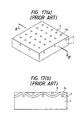
- the method comprising embedding a metal-made mesh electrode in the surface of a PTC composition (shown in Fig. 17) fails to reduce the resistivity for the size of the PTC composition and is also disadvantageous in that the resistivity is instable.
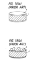
- the method consisting of direct plating with metal or sputtering tends to involve development of wrinkles or cracks in the electrode film or separation of the electrode film from the PTC composition due to thermal expansion and shrinkage of the PTC composition as shown in Fig. 18.
- An object of the invention is to provide an organic PTC thermistor which can be produced without any difficulty in kneading of conductive powder or in molding and which is excellent in room temperature resistivity, rate of resistivity change, and repeatability.
- Another object of the invention is to provide an organic PTC thermistor which is free from instability of resistivity or unfavorable increase of resistivity which might be caused by an electrode.
- An organic PTC thermistor having a positive temperature coefficient of resistivity which comprises a PTC composition comprising an organic polymer having dispersed therein a conductive substance, and at least one pair of electrodes, wherein the conductive substance is tungsten carbide powder is known from WO-A-91 19 297.
- the present invention provides an organic PTC thermistor having a positive temperature coefficient of resistivity, which is defined by the features of claim 1.
- the thermistor comprises at least one pair of electrodes, wherein the electrodes each may comprise a metal mesh and a metal layer.
- the inventors have extensively studied organic PTC thermistors comprising an organic polymer having incorporated therein non-oxide ceramic powder as a conductive substance. They have found as a result that use of tungsten carbide (hereinafter abbreviated as WC) powder as a conductive substance makes it possible to reduce a room temperature resistivity at a smaller content than has been required of other non-oxide ceramics and yet to achieve a high rate of resistivity change while obtaining excellent repeatability.
- WC tungsten carbide
- thermistors of prescribed size prepared from polyvinylidene fluoride (hereinafter abbreviated as PVDF) and a proper amount, e.g., 30% by volume of ZrN, whose volume resistivity at room temperature is nearly the same as that of WC, had a room temperature surface resistivity of 200 M ⁇ or higher, proving impractical.
- the room temperature surface resistivity of the thermistor of the same size containing 30% by volume of WC was as incomparably low as 0.007 ⁇ .
- a desired room temperature volume resistivity of a PTC thermistor for the uses intended in the present invention is 10 ⁇ •cm or lower. According to the invention, such a low level of room temperature volume resistivity can easily be attained by using WC at a smaller content.
- the invention is characterized in that WC powder is used as a conductive substance in an organic PTC thermistor to reduce a volume resistivity at room temperature (25°C) to 10 ⁇ •cm or lower.
- the WC powder to be used has an average particle size of not greater than 10 ⁇ m in order to secure a prescribed low breakdown voltage, and still preferably not greater than 1 ⁇ m for further reducing the room temperature resistivity.
- WC powder smaller than 0.1 ⁇ m is expensive and difficult to knead. Accordingly, the average particle size is 0.1 to 10 ⁇ m, still preferably 0.1 to 1 ⁇ m, particularly preferably 0.5 to 1 ⁇ m.
- the organic polymer used in the invention is not particularly limited as long as it is a thermoplastic and crystalline polymer.
- PVDF polyvinylidene fluoride
- polypropylene polypropylene
- polyvinyl chloride polyvinyl acetate
- an ionomer or a copolymer comprising monomers of these polymers
- PVDF exhibits self-extinguishing properties (properties of spontaneously extinguishing the fire it has caught upon removal of a flame)
- it is suited for use in places having fear of fire.
- the amount of WC powder to be added ranges from 20 to 50% by volume, preferably from 23 to 50% by volume, still preferably from 25 to 40% by volume, based on the PTC composition. If the WC content is less than 20%, a rise of room temperature resistivity is observed. If it exceeds 50%, the ratio of the powder to the polymer is so high that the torque required for kneading increases, tending to make kneading and molding difficult.
- thermistor of the first embodiment is not restricted by process of production, the following process may be mentioned as a typical example.
- a PTC composition comprising a crystalline polymer having dispersed therein WC is kneaded in a kneading machine, such as a Banbury mixer or a mixing roll.
- An antioxidant or a kneading assistant, such as a surface active agent, may be added in this stage.
- the resulting blend is molded with a hot press into a sheet or a film.
- the polymer may be subjected to crosslinking for inhibiting the fluidity after PTC manifestation thereby to stabilize the resistivity.
- the crosslinking can be carried out by electron-induced crosslinking in the presence a crosslinking assistant (added to enhance the efficiency of electron rays or crosslinking efficiency) (see U.S. Patent 3,269,862), chemical crosslinking, or water-induced crosslinking comprising grafting a silane compound to a crystalline polymer in the presence of a free radical generator and then bringing the graft polymer into contact with water or an aqueous medium in the presence of a silanol condensation catalyst (see JP-B-4-11575).
- a crosslinking assistant added to enhance the efficiency of electron rays or crosslinking efficiency
- chemical crosslinking or water-induced crosslinking comprising grafting a silane compound to a crystalline polymer in the presence of a free radical generator and then bringing the graft polymer into contact with water or an aqueous medium in the presence of a silanol condensation catalyst
- each electrode is formed on both main sides facing each other by press bonding a metal plate under heat (see U.S. Patent 4,426,633), plating with metal (see JP-B-4-44401), coating with a conductive paste (see JP-A-59-213102), sputtering (see JP-A-62-85401), flame spray coating (see JP-A-62-92409), and the like. It is particularly preferable that each electrode has the structure according to the second embodiment of the invention hereinafter described, i.e., a combination of a metal mesh and a metal layer.
- the resulting PTC sheet is punched or cut out to a prescribed shape and size, and a metallic lead wire is soldered to each electrode.
- the PTC thermistor may be encapsulated in an insulating resin, or a conductive adhesive may be applied to the electrode, via which a terminal made of another metal can be connected.
- the thermistor may have a multilayer structure in which a plurality of PTC sheets and a plurality of electrode layers alternate so as to have two or more pairs of electrodes facing each other with a PTC sheet therebetween.
- a structure can be formed by a sheeting method or a printing method, or a combination of these methods and a thin film formation technique, such as sputtering.
- the thermistor according to an embodiment of the invention is then described below.
- the organic PTC thermistor of this embodiment is characterized in that a pair of electrodes have a structure composed of a combination of a metal mesh and a metal layer.
- the PTC thermistor can have a resistivity correspondent with the size of the PTC composition and exhibits stabilized resistivity.
- the metal mesh is preferably provided by embedding in the surface of a PTC composition with a part of it exposed.
- the initial resistivity of the PTC composition decreases, and the stress by thermal stress can be relaxed, which provides mechanical reinforcement for preventing the PTC composition and electrodes from being deformed or developing cracks, etc.
- the metal mesh preferably has an opening size of 200 to 600 mesh.
- the metal mesh having the preferred opening size can be prepared at low cost and is easy to punch or cut into a prescribed shape.
- the metal mesh is preferably at least one of plain weave mesh, twilled weave mesh, plain weave mesh having been squashed (flattened), twilled weave mesh having been squashed (flattened), and mesh with no difference in level at the intersections.
- the metal mesh can have a reduced thickness while providing an increased exposed area of the metal on the surface of the PTC composition, the final product can thus have a reduced thickness, and the abrading operation (hereinafter described) is easier.
- the metal layer is preferably at least one of a metal layer formed by chemical plating, a metal layer formed by electroplating, a metal layer formed by vacuum vapor phase deposition, and a metal layer formed by flame spray coating.
- the PTC composition can have a reduced initial resistivity.
- the metal layer is preferably formed after the above-described metal mesh has been embedded with a part of it exposed and the surface of the PTC composition containing the exposed metal mesh has been abraded to increase the exposed area of the mesh and the conductive substance. In this case, the resistivity can be stabilized and is further reduced.
- the organic polymer in the organic PTC thermistor of this embodiment is not particularly limited, and can be preferably selected from polyethylene, polypropylene, polyvinylidene fluoride, polyvinyl chloride, polyvinyl acetate, an ionomer, or a copolymer comprising monomers of these polymers.
- the conductive substance is tungsten carbide (WC) . Use of WC provides a PTC thermistor having a reduced resistivity and excellent stability of R-T characteristics against repetition and makes it feasible to reduce the size of the PTC thermistor.
- Fig. 1(a) is a perspective view of the organic PTC thermistor according to the second embodiment, in which a metal mesh is embedded in the surface of a PTC composition having a sheet form.
- Fig. 1(b) is a cross section of Fig. 1(a) along line A-A'.
- numeral 1 denotes a body of a PTC composition
- 2 denotes a metal mesh
- 2a denotes an intersection of the metal mesh
- 3 denotes a metal layer.
- the thermistor of the latter embodiment is not restricted by process of production.
- it is produced by kneading an organic polymer and a conductive substance, molding the blend and, if desired, subjecting the molded article to crosslinking in the same manner as in the first embodiment. Thereafter, a metal mesh is embedded in each of the main surfaces of the molded article by, for example, press bonding under heat.
- the mesh desirably has fine mesh, a metal mesh having extreme fineness is of little real use because of its high cost of production.
- a coarse metal mesh will have a larger wire thickness than in usual metal meshes so that the stock sheet after formation of electrodes has poor workability in punching or cutting to a prescribed shape. Besides, burrs tend to be formed at edges on punching or cutting. From these considerations, the mesh preferably has an opening size of 200 to 600 mesh.
- the term "mesh" as used as a unit of mesh fineness means the number of openings in a 1 inch square.
- Materials of the metal mesh include stainless steel, copper, iron, nickel, and brass.
- the weave of the metal mesh includes a plain weave, a twill weave, and an irregular weave.
- the mesh may be squashed (flattened), or the mesh may be plated with another metallic material.
- the difference in level between wires is preferably as small as possible.
- a mesh having no difference in level at the intersections which can be prepared by etching or punching is also useful.
- the metal mesh is not completely buried under the surface of the PTC composition but be embedded with the upper portion of the mesh being uniformly exposed on the surface of the PTC composition as shown in Fig. 1(b). Thereafter, the surface comprising the PTC composition and the exposed metal mesh is preferably subjected to surface graining by mechanical abrasion with a sand blast, a sand paper, etc. or chemical abrasion with an acid to increase the exposed area of the mesh.
- a metal layer is then formed on the metal mesh-embedded surface by chemical plating, electroplating, vacuum vapor phase deposition (vacuum evaporation or sputtering) or flame spray coating.
- the plating metal is not particularly limited and includes Ni, Cu, Ag, Sn, and Cr.
- the stock sheet is worked into a desired size by punching or cutting, and a metallic lead wire is soldered to each electrode.
- the PTC thermistor may be encapsulated in an insulating resin, or a conductive adhesive may be applied to the electrode, via which an outer metallic terminal can be connected.
- the organic PTC thermistors of the invention are useful as an overcurrent preventive element in various small D.C. motors for driving door locks, outside mirror (door mirror) control, and power windows of automobiles; and secondary batteries, such as lithium batteries, nickel-hydrogen batteries, and nickelcadmium batteries. They are also useful as an overcurrent preventive element in a radiofrequency current circuit as in an overheat preventive apparatus used in a back-lighting fluorescent tube.
- the thermistors which use tungsten carbide as a conductive substance exhibit excellent resistance characteristics in the radiofrequency region, they are preferably used as an overcurrent preventive element in a radiofrequency current circuit as in an overheat preventive apparatus used in a back-lighting fluorescent tube.
- a back-lighting fluorescent tube for a liquid crystal display used in portable personal computers or word processors, etc. is generally made of a transparent material such as glass, the inner wall of which is coated with a fluorescent substance, and which is filled with gas for discharging. On applying an alternating or direct current to the electrodes positioned at each end of the tube, a discharge takes place through the gas.
- Ultraviolet rays having a wavelength of 253.7 nm excited by mercury gas irradiates the fluorescent substance on the inner wall of the tube and converted to visible light.
- the electrodes for this kind of fluorescent tubes include a hot cathode and a cold cathode.
- Sharp Giho proposes to use a system in which a temperature fuse is brought into contact with the electrode side so that the circuit may be broken in case of abnormal heat generation.
- the temperature fuse be cut in case of abnormal heat generation, the liquid crystal display gets out of use, and both the fluorescent tube and the temperature fuse have to be renewed.
- the PTC thermistor of the present invention which is capable of radiofrequency current control can be used as an overheat preventive element which is brought into thermal contact with a fluorescent tube, i.e., in intimate contact with the electrode portion of a fluorescent tube.
- the thermistor of the invention provides a small, light, and economical overheat preventive apparatus for a fluorescent tube.
- the electrode terminal of the thermistor and one electrode lead of the fluorescent tube are electrically connected, and the thermistor is integrated into the lighting circuit of the fluorescent tube with series connection.
- the thermistor forms a detecting circuit dependent of the lighting circuit of the fluorescent tube, and an increase of resistivity of the thermistor due to abnormal overheat of the fluorescent tube is detected.
- Fig. 2 illustrates PTC thermistor 15 prepared by molding a PTC composition into a cylinder and forming electrodes 17 of Ni, Ag, etc., which is fitted into electrode 18 of a fluorescent tube.
- Fig. 3 illustrates PTC thermistor 15 prepared by forming a PTC composition into a disk followed by calcination, which is electrically connected to the terminal lead of a fluorescent tube by, for example, soldering. Either example is characterized in that the PTC thermistor is thermally in contact with the end of the electrode of a fluorescent tube. If desired, a heat shrinkable tube may be put on both the thermistor and the end of the fluorescent tube electrode in order to assure an intimate contact therebetween.
- the PTC thermistor shows an abrupt rise of resistivity, which can be detected in detecting circuit 16 (see Fig. 4).
- the PTC thermistor is connected in series to the electrode of fluorescent tube 14, the current passing through lighting circuit 13 of the fluorescent tube is limited according to the resistivity rise of the PTC thermistor so that the heat generation at the fluorescent tube electrode is suppressed, and the life of the fluorescent tube can be prolonged (see Fig. 5).
- numeral 11 denotes a DC power source and 12 denotes a switch.
- the PTC thermistor may be held by a holder so as to be removably fitted to the electrode portion of a fluorescent tube. Further, as shown in Fig. 6, PTC thermistor 15 in a sheet form may be wound around the end of a fluorescent tube.
- the thermistor of the invention having PTC characteristics used as an abnormal overheat preventive apparatus.
- the PTC thermistor can be repeatedly reused. Since the PTC thermistor prevents abnormal heat generation at the electrode portion while an arc discharge is changed to a glow discharge in the end of the life of a fluorescent tube, it functions as a protection of the surrounding equipment including the liquid crystal against thermal damage.
- the PTC thermistor is connected in series to a fluorescent tube lighting circuit, since the current is limited according as the resistivity of the thermistor rises due to abnormal heat generation, the life of the fluorescent tube can be extended. What happens when a fluorescent tube is coming to its end is mere darkening of the liquid crystal display screen, which visually teaches a user when to renew the fluorescent tube.
- Example 8 is not an embodiment of the invention, but is useful for its understanding. Unless otherwise indicated, all the parts are by weight.
- JP-B-4-11575 100 parts of PVDF (KYNAR 711, produced by Elf Atochem North America) was mixed with 10 parts of a silane coupling agent (KBC1003, produced by Shin-Etsu Chemical Co., Ltd.) and 1 part of 2,5-dimethyl-2,5-di(t-butylperoxy)hexyn-3, and the mixture was kneaded in a twin-screw extruder at 200°C to prepare a grafted polymer.
- a silane coupling agent KBC1003, produced by Shin-Etsu Chemical Co., Ltd.
- WC powder (WC-F, produced by Nippon Shinkinzoku K.K.; average particle size: 0.65 ⁇ m) was added to the grafted polymer in a proportion of 20% by volume based on the resulting composition, and the mixture was kneaded in a kneading machine at 200°C and 25 rpm for 1 hour to prepare a PTC composition.
- the PTC composition was hot pressed at 200°C and 30 kgf/cm 2 to obtain a sheet having a thickness of about 1 mm.
- a nickel foil, one surface of which was roughened, (available from Fukuda Metal Foil & Powder Co., Ltd.) was adhered to each side of the sheet with the roughened surface thereof being in contact with the sheet and press bonded at 200°C and 30 kgf/cm 2 , followed by allowing to cool at room temperature to form a pair of electrode layers.
- the sheet with electrodes was punched into a disk of 10 mm in diameter to obtain a PTC thermistor.
- PTC thermistors were prepared in the same manner as in Example 1, except for changing the amount of WC added to 25% by volume, 30% by volume, or 40% by volume, based on the resulting PTC composition.
- PTC thermistors were prepared in the same manner as in Example 2, except for using WC powder having an average particle size of 2.09 ⁇ m (WC-25, produced by Nippon Shinkinzoku K.K.), 4.82 ⁇ m (WC-50, produced by Nippon Shinkinzoku K.K.), 8.60 ⁇ m (WC-90, produced by Nippon Shinkinzoku K.K.), or 75 ⁇ m (WC-S, produced by Nippon Shinkinzoku K.K.).
- a PTC thermistor was prepared in the same manner as in Example 2, except for replacing KYNAR 711 with KYNAR 461, PVDF produced by the same manufacturer.
- KYNAR 461 and KYNAR 711 are different in melt viscosity.
- the viscosity of KYNAR 461 is 28,000 poise while that of KYNAR 711 is 7,000 poise, both as measured with a Monsant Capillary Viscometer at 230°C.
- PE polyethylene
- HiZex 2100P silane coupling agent
- DCP dicumyl peroxide
- a PTC thermistor was prepared in the same manner as in Example 2, except for using the above-prepared graft polymer and setting the kneading temperature at 140°C.
- EVA ethylene-vinyl acetate copolymer
- KBE1003 silane coupling agent
- a PTC thermistor was prepared in the same manner as in Example 2, except for using the above-prepared graft polymer and setting the kneading temperature at 120°C.
- PTC thermistor was prepared in the same manner as in Example 3, except for using WC powder having an average particle size of from 0.1 to 0.2 ⁇ m (WC02N, produced by Tokyo Tungsten Co., Ltd.).
- PTC thermistors were prepared in the same manner as in Example 1, except for changing the kind and/or the amount of the conductive powder as follows.
- Titanium nitride TiN (TiN-01 produced by Nippon Shinkinzoku K.K.; average particle size: 1.37 ⁇ m), added in an amount of 30 vol% (based on the resulting PTC composition; hereinafter the same).
- Zirconium nitride ZrN (ZrN, produced by Nippon Shinkinzoku K.K.; average particle size: 1.19 ⁇ m), added in an amount of 30 vol%.
- Titanium carbide TiC (TiC-007, produced by Nippon Shinkinzoku K.K.; average particle size: 0.88 ⁇ m), added in an amount of 40 vol%.
- Titanium boride TiB 2 (TiB 2 -PF, produced by Nippon Shinkinzoku K.K.; average particle size: 1.80 ⁇ m), added in an amount of 30 vol%.
- Molybdenum silicide MoSi 2 (MoSi 2 -F, produced by Nippon Shinkinzoku K.K.; average particle size: 1.60 ⁇ m), added in an amount of 40 vol%.
- Nickel Ni (filamentous Ni powder #210, produced by INCO; average particle size: 0.5 to 1.0 ⁇ m), added in an amount of 25 vol%.
- Carbon black (CB) (Toka Black #4500, produced by Tokai Carbon Co., Ltd.), added in an amount of 30 vol%.
- Tungsten carbide WC (WC-F) added in an amount of 18 vol%.
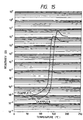
- Fig. 7 shows the p-T characteristics of Examples 1 to 4 and Comparative Example 8.
- the room temperature surface resistivity exceeds 300 M ⁇ at a WC content of 18 vol%, which is too high for practical use.
- a preferred WC content for securing practical utility is 23 vol% or more, and the room temperature surface resistivity becomes lower as the WC content increases.
- the kneading torque becomes greater as the WC content increases.
- the amount of WC to be added ranges from 20 to 50 vol%, more preferably from 23 to 50 vol%, still preferably from 25 to 40 vol%, based on the PTC composition.
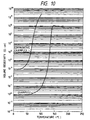
- Fig 8 is a graph showing ⁇ -T characteristics dependent on the average particle size of WC.
- the room temperature surface resistivity increases as the average particle size of WC increases. If the average particle size is too large, increase of instability of resistivity is observed. It was revealed that if the average particle size exceeds 50 ⁇ m as in Example 8, the breakdown voltage V b becomes seriously low. In order to ensure a high breakdown voltage of 180 V or more, it is preferable that WC has an average particle size of not more than 10 ⁇ m as is apparent from the results of Examples 1 to 7.
- a still preferred average particle size of WC is not greater than 1 ⁇ m.
- WC powder having an average particle size smaller than 0.1 ⁇ m is not only expensive but causes an increase in kneading torque and makes kneading difficult, so that a preferred average particle size is 0.1 ⁇ m or greater.
- the average particle size is as small as is preferred, the same performance as described above can be assured even if the kind of PVDF is altered as in Example 9 or if PVDF is replaced with other organic polymers, such as PE or EVA, as shown in Table 1 and Fig. 9. It was confirmed in these cases that an increase in WC average particle size results in the same tendencies as to breakdown voltage, resistivity, and resistivity stability as observed with PVDF.
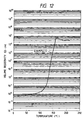
- Fig. 11 is a graph showing p-T characteristics observed with WC in comparison with those observed with Ni or CB.
- the Ni-containing sample was also found inferior in heat resistance and reliability, such as repeatability.
- a sheet of a PTC composition was prepared in the same manner as in Example 1, except for increasing the WC content to 30 vol%.
- a stainless steel-made plain weave mesh having an opening size of 200 mesh was embedded on each side of the sheet at 200°C under a load of 30 kgf/cm 3 . After allowing to cool to room temperature, both sides of the sheet was electroless-plated with Ni to a thickness of 1 to 2 ⁇ m. The sheet was punched into a disk having a diameter of 10 mm to obtain a PTC element.
- a PTC element was prepared in the same manner as in Example 13, except that the each surface of the sheet before Ni plating, with the mesh embedded in, was abraded with a sand paper to increase the exposed area of the mesh.
- a PTC element was prepared in the same manner as in Example 13, except that Ni electroless plating was replaced with vacuum evaporation of Cu at a chamber temperature of 160°C to form a Cu layer having a thickness of 1 to 2 ⁇ m.
- a PTC element was prepared in the same manner as in Example 15, except that the each surface of the sheet before Cu deposition, with the mesh embedded in, was abraded with a sand paper to increase the exposed area of the mesh.
- a PTC element was prepared in the same manner as in Example 15, except for changing the opening size of the mesh to 400 mesh.
- a PTC element was prepared in the same manner as in Example 15, except for replacing the mesh having an opening size of 200 mesh with a stainless steel-made mesh having an opening size of 400 mesh and having no difference in level at the intersections.
- a PTC element was prepared in the same manner as in Example 13, except that each electrode was formed only by Ni plating without using the metal mesh.
- a PTC element was prepared in the same manner as in Example 13, except that Ni plating was not conducted.
- a PTC element was prepared in the same manner as in Example 15, except that each electrode was formed only by Cu vacuum evaporation without using the metal mesh.
- An adhesive tape (T4000, produced by Sony Chemical Co., Ltd.) was adhered to the entire surface of the electrode and rapidly stripped off. The adhesion of the electrode was judged by whether or not the electrode was peeled.
- the electrode structure formed by embedding a metal mesh followed by plating or vacuum evaporation is effective to reduce the initial resistivity while relaxing the stress due to thermal stress thereby enhancing mechanical strength of the PTC sheet and the electrodes and preventing deformation or development of cracks, etc. (Examples 13, 15, and 17).
- the electrode consists solely of metal layer 3 formed by plating or vacuum evaporation as shown in Fig. 18(b) (Reference Examples 1 and 3)
- PTC sheet 1 or metal layer 3 tend to undergo deformation or development of wrinkles or cracks due to the difference between the PTC sheet and the metal layer in coefficient of linear expansion.
- embedded mesh 2 as in Examples relaxes the stress at the openings of the mesh and also serves as a support of metal layer 3, producing a so-called anchor effect.
- the problems which might occur with the electrode formed solely of metal layer 3 can thus be solved.
- a low resistivity can be obtained by addition of a smaller amount of the conductive powder than has been required of other conductive ceramic powders.
- kneading with the organic polymer and subsequent molding can be carried out easier to facilitate the production of small-sized thermistors for high-current circuits.
- conductive ceramic powder is chemically more stable than metal and harder and more resistant to heat than metal or carbon black, it provides a highly reliable thermistor having excellent mechanical strength, stable resistivity, stability of performance against repetition of thermal cycles, and a high breakdown voltage.
- the WC-containing thermistors of the invention show a lower resistivity at room temperature and a greater rate of resistivity change with temperature.
- the thermistor of the present invention are effective in uses where lower electrical resistance and higher heat resistance are demanded, for example, for prevention of overcurrent due to a shortcircuit of a charging or discharging circuit of secondary batteries, prevention of overcurrent due to lock of a motor typified by a door lock motor of automobiles, and prevention of overcurrent due to a shortcircuit of a telecommunication circuit.
- difficulty of kneading can be avoided by using WC powder having an average particle size of not smaller than 0.1 ⁇ m, and a thermistor having a low room temperature resistivity, a large rate of resistivity change, and a high breakdown voltage can be obtained by using WC powder having an average particle size of not greater than 10 ⁇ m.
- polyvinylidene fluoride polyethylene, polypropylene, polyvinyl chloride, polyvinyl acetate, an ionomer, or a copolymer comprising monomers of these polymers is selected as an organic polymer with which WC is to be kneaded, whereby a thermistor excellent in room temperature resistivity, rate of resistivity change, breakdown voltage, repeatability, and reliability can be obtained.
- a thermistor having a low room temperature resistivity and a high rate of resistivity change can be obtained by adding at least 20% by volume of WC, and ease of kneading and molding can be assured to facilitate production of a thermistor by limiting the amount of WC added to 50% by volume at the most.
- a part of the metal mesh is exposed on the surface of the PTC composition, whereby the initial resistivity can further be lowered, and the stress due to thermal stress can be relaxed to afford mechanical reinforcement against deformation of the PTC composition or development of wrinkles or cracks in the electrode.
- the metal mesh used has an opening size of 200 to 600 mesh, whereby the resulting stock sheet can be punched or cut with ease and at low cost.
- the metal mesh used is selected from plain weave mesh, twilled weave mesh, plain weave mesh having been squashed (flattened), twilled weave mesh having been squashed (flattened), and mesh with no difference in level at the intersections thereof, whereby a PTC element having a further reduced thickness can be prepared, the abrasion operation is easier, and the production process can be simplified.
- the metal layer is formed by chemical plating, electroplating, vacuum vapor phase deposition or flame spray coating, whereby the initial resistivity can be lowered.
- the metal layer is formed on the abraded surface of the PTC composition including the embedded metal mesh, whereby the surface resistivity is stabilized and is further lowered.
- WC is used as a conductive substance, whereby a PTC thermistor excellent in resistivity, rate of resistivity change, breakdown voltage, repetition stability of R-T characteristics, and reliability can be obtained.
Landscapes
- Engineering & Computer Science (AREA)
- Microelectronics & Electronic Packaging (AREA)
- Chemical & Material Sciences (AREA)
- Dispersion Chemistry (AREA)
- Ceramic Engineering (AREA)
- Physics & Mathematics (AREA)
- Electromagnetism (AREA)
- Thermistors And Varistors (AREA)
Description
- This invention relates to an organic polymer thermistor exhibiting a positive temperature coefficient of resistivity (PTC) (hereinafter referred to as an organic PTC thermistor). More particularly, it relates to an organic PTC thermistor useful as a preventive element against overcurrent in the door lock motor of automobiles or batteries or as a preventive element against overheat of a back-lighting fluorescent tube.
- Conductive compositions comprising an organic polymer, such as polyethylene or polypropylene, having dispersed therein conductive powder, such as carbon black or metallic powder, exhibits PTC characteristics. These conductive compositions are known to have a lower volume resistivity at room temperature as compared with conventional ceramic PTC compositions, to be capable of being used in high current circuits, to be expected to have a reduced size, and to show a high rate of resistivity change with temperature (i.e., maximum resistivity/room temperature resistivity). Known organic conductive compositions are disclosed, e.g., in U.S. Patents 3,591,526 and 3,673,121.
- Thermistors comprising an organic polymer containing, as a conductive powder, a non-oxide ceramic powder, such as TiC, TiB2, TiN, ZrC, ZrB2, ZrN, and NbC, are disclosed, e.g., in JP-A-2-86087 (the term "JP-A" as used herein means an "unexamined published Japanese patent application"), Journal of Materials Science Letters, No. 9, pp. 611-612 (1990), and ibid, No. 26, pp. 145-154 (1991).
- Known techniques for forming electrodes on these PTC compositions include direct plating of metal (JP-B-4-44401, the term "JP-B" as used herein means an "examined published Japanese patent application"), embedding of a metal-made mesh electrode in the PTC composition (JP-B-2-16002), and sputtering (JP-A-62-85401).
- It is generally desired for PTC thermistors used as an overcurrent preventive element for the door lock motor of an automobile or batteries to have a room temperature volume resistivity of not higher than 1 Ω•cm and a rate of resistivity change as expressed by the following equation of not less than 5.
- A practically useful organic thermistor containing carbon black as a conductive substance has a high room temperature resistivity of about 2 Ω•cm, which is hardly expected to be further lowered, and has been deemed unsuited for use in high current circuits. Thermistors using metallic powder as a conductive substance achieve a reduced room temperature volume resistivity but exhibit poor durability against actual load in an on-off test, etc., proving impractical.
- The above-mentioned thermistors comprising an organic polymer having dispersed therein non-oxide ceramic powder are excellent in heat resistance, mechanical strength and chemical stability and are expected to have satisfactory repeatability and stability when used for prevention of overcurrent due to a shortcircuit of a secondary battery in charging or discharging or lock of a motor. However, the non-oxide ceramic powder incorporated into an organic polymer cannot have a reduced resistivity unless it is added in a considerably increased amount as compared with carbon black. Use of such an increased amount of the non-oxide ceramic powder results in difficulties in kneading and molding. Besides, it has been difficult to obtain a small-sized thermistor suitable for high current circuits.
- With respect to formation of electrodes, the method comprising embedding a metal-made mesh electrode in the surface of a PTC composition (shown in Fig. 17) fails to reduce the resistivity for the size of the PTC composition and is also disadvantageous in that the resistivity is instable. The method consisting of direct plating with metal or sputtering tends to involve development of wrinkles or cracks in the electrode film or separation of the electrode film from the PTC composition due to thermal expansion and shrinkage of the PTC composition as shown in Fig. 18.
- An object of the invention is to provide an organic PTC thermistor which can be produced without any difficulty in kneading of conductive powder or in molding and which is excellent in room temperature resistivity, rate of resistivity change, and repeatability.
- Another object of the invention is to provide an organic PTC thermistor which is free from instability of resistivity or unfavorable increase of resistivity which might be caused by an electrode.
- These and other objects and effects of the invention will be obvious from the description hereinafter given.
- An organic PTC thermistor having a positive temperature coefficient of resistivity, which comprises a PTC composition comprising an organic polymer having dispersed therein a conductive substance, and at least one pair of electrodes, wherein the conductive substance is tungsten carbide powder is known from WO-A-91 19 297.
- The present invention provides an organic PTC thermistor having a positive temperature coefficient of resistivity, which is defined by the features of
claim 1. - The thermistor comprises at least one pair of electrodes, wherein the electrodes each may comprise a metal mesh and a metal layer.
-
- Figs. 1(a) and 1(b) show an organic PTC thermistor according to an embodiment of the invention, in which the thermistor has a sheet form with a metal mesh embedded in the surface thereof.
- Figs. 2(a), 2(b) and 2(c) show an example of an overheat preventive apparatus in which the PTC thermistor of the invention is used.
- Fig. 3 shows another example of an overheat preventive apparatus in which the PTC thermistor of the invention is used.
- Fig. 4 is a detecting circuit diagram in which the PTC thermistor of the invention is used as a heat sensor.
- Fig. 5 is a circuit diagram in which the PTC thermistor is connected in series to the electrode of a fluorescent tube.
- Fig. 6 shows a further example of an overheat preventive apparatus in which the PTC thermistor of the invention is used.
- Fig. 7 is a graph showing volume resistivity-temperature (ρ-T) characteristics dependent on the tungsten carbide (WC) content in a polyvinylidene fluoride (PVDF) composition.
- Fig. 8 is a graph showing ρ-T characteristics dependent on the average particle size of WC in a PVDF composition.
- Fig. 9 is a graph showing ρ-T characteristics of PTC observed with various organic polymers.
- Fig. 10 is a graph showing ρ-T characteristics observed with conductive powder WC in comparison with those observed with TiC.
- Fig. 11 is a graph showing ρ-T characteristics observed with conductive powder WC in comparison with those observed with Ni or carbon black.
- Fig. 12 is a graph showing representative ρ-T characteristics when fine conductive powder WC having an average diameter of from 0.1 to 0.2 µm.
- Fig. 13 is a graph showing surface resistivity-temperature characteristics (R-T characteristics) observed in Examples 13 and 14.
- Fig. 14 is a graph showing R-T characteristics observed in Examples 15 and 16.
- Fig. 15 is a graph showing R-T characteristics observed in Examples 17 and 18.
- Fig. 16 is a graph showing R-T characteristics observed in Examples 15 and Reference Example 2.
- Figs. 17(a) and 17(b) show a conventional PTC thermistor.
- Figs. 18(a) and 18(b) show development of a thermal stress in the measurement of R-T characteristics of a conventional PTC thermistor.
-
- The invention will be explained below.
- The inventors have extensively studied organic PTC thermistors comprising an organic polymer having incorporated therein non-oxide ceramic powder as a conductive substance. They have found as a result that use of tungsten carbide (hereinafter abbreviated as WC) powder as a conductive substance makes it possible to reduce a room temperature resistivity at a smaller content than has been required of other non-oxide ceramics and yet to achieve a high rate of resistivity change while obtaining excellent repeatability.
- For example, all the thermistors of prescribed size prepared from polyvinylidene fluoride (hereinafter abbreviated as PVDF) and a proper amount, e.g., 30% by volume of ZrN, whose volume resistivity at room temperature is nearly the same as that of WC, had a room temperature surface resistivity of 200 MΩ or higher, proving impractical. On the other hand, the room temperature surface resistivity of the thermistor of the same size containing 30% by volume of WC was as incomparably low as 0.007 Ω.
- It has not yet been made clear why such a great difference in room temperature resistivity is produced in spite of the equality of the two conductive substances in volume resistivity, with the compounding ratio being equal. The difference seems attributable to the compatibility between the conductive substance and the organic polymer matrix. As previously mentioned, a desired room temperature volume resistivity of a PTC thermistor for the uses intended in the present invention is 10 Ω•cm or lower. According to the invention, such a low level of room temperature volume resistivity can easily be attained by using WC at a smaller content.
- That is, the invention is characterized in that WC powder is used as a conductive substance in an organic PTC thermistor to reduce a volume resistivity at room temperature (25°C) to 10 Ω•cm or lower.
- The WC powder to be used has an average particle size of not greater than 10 µm in order to secure a prescribed low breakdown voltage, and still preferably not greater than 1 µm for further reducing the room temperature resistivity. WC powder smaller than 0.1 µm is expensive and difficult to knead. Accordingly, the average particle size is 0.1 to 10 µm, still preferably 0.1 to 1 µm, particularly preferably 0.5 to 1 µm.
- The organic polymer used in the invention is not particularly limited as long as it is a thermoplastic and crystalline polymer. For example, polyvinylidene fluoride (PVDF) polyethylene, polypropylene, polyvinyl chloride, polyvinyl acetate, an ionomer, or a copolymer comprising monomers of these polymers can be used. In particular, because PVDF exhibits self-extinguishing properties (properties of spontaneously extinguishing the fire it has caught upon removal of a flame), it is suited for use in places having fear of fire.
- The amount of WC powder to be added ranges from 20 to 50% by volume, preferably from 23 to 50% by volume, still preferably from 25 to 40% by volume, based on the PTC composition. If the WC content is less than 20%, a rise of room temperature resistivity is observed. If it exceeds 50%, the ratio of the powder to the polymer is so high that the torque required for kneading increases, tending to make kneading and molding difficult.
- While the thermistor of the first embodiment is not restricted by process of production, the following process may be mentioned as a typical example. A PTC composition comprising a crystalline polymer having dispersed therein WC is kneaded in a kneading machine, such as a Banbury mixer or a mixing roll. An antioxidant or a kneading assistant, such as a surface active agent, may be added in this stage. The resulting blend is molded with a hot press into a sheet or a film. While not essential, the polymer may be subjected to crosslinking for inhibiting the fluidity after PTC manifestation thereby to stabilize the resistivity. The crosslinking can be carried out by electron-induced crosslinking in the presence a crosslinking assistant (added to enhance the efficiency of electron rays or crosslinking efficiency) (see U.S. Patent 3,269,862), chemical crosslinking, or water-induced crosslinking comprising grafting a silane compound to a crystalline polymer in the presence of a free radical generator and then bringing the graft polymer into contact with water or an aqueous medium in the presence of a silanol condensation catalyst (see JP-B-4-11575).
- An electrode is formed on both main sides facing each other by press bonding a metal plate under heat (see U.S. Patent 4,426,633), plating with metal (see JP-B-4-44401), coating with a conductive paste (see JP-A-59-213102), sputtering (see JP-A-62-85401), flame spray coating (see JP-A-62-92409), and the like. It is particularly preferable that each electrode has the structure according to the second embodiment of the invention hereinafter described, i.e., a combination of a metal mesh and a metal layer.
- If desired, the resulting PTC sheet is punched or cut out to a prescribed shape and size, and a metallic lead wire is soldered to each electrode. If desired, the PTC thermistor may be encapsulated in an insulating resin, or a conductive adhesive may be applied to the electrode, via which a terminal made of another metal can be connected.
- Unlike the above-described structures, the thermistor may have a multilayer structure in which a plurality of PTC sheets and a plurality of electrode layers alternate so as to have two or more pairs of electrodes facing each other with a PTC sheet therebetween. Such a structure can be formed by a sheeting method or a printing method, or a combination of these methods and a thin film formation technique, such as sputtering.
- The thermistor according to an embodiment of the invention is then described below.
- The organic PTC thermistor of this embodiment is characterized in that a pair of electrodes have a structure composed of a combination of a metal mesh and a metal layer. By virtue of this electrode structure, the PTC thermistor can have a resistivity correspondent with the size of the PTC composition and exhibits stabilized resistivity.
- The metal mesh is preferably provided by embedding in the surface of a PTC composition with a part of it exposed. In this case, the initial resistivity of the PTC composition decreases, and the stress by thermal stress can be relaxed, which provides mechanical reinforcement for preventing the PTC composition and electrodes from being deformed or developing cracks, etc.
- The metal mesh preferably has an opening size of 200 to 600 mesh. The metal mesh having the preferred opening size can be prepared at low cost and is easy to punch or cut into a prescribed shape.
- The metal mesh is preferably at least one of plain weave mesh, twilled weave mesh, plain weave mesh having been squashed (flattened), twilled weave mesh having been squashed (flattened), and mesh with no difference in level at the intersections. In this case, the metal mesh can have a reduced thickness while providing an increased exposed area of the metal on the surface of the PTC composition, the final product can thus have a reduced thickness, and the abrading operation (hereinafter described) is easier.
- The metal layer is preferably at least one of a metal layer formed by chemical plating, a metal layer formed by electroplating, a metal layer formed by vacuum vapor phase deposition, and a metal layer formed by flame spray coating. In this case, the PTC composition can have a reduced initial resistivity.
- The metal layer is preferably formed after the above-described metal mesh has been embedded with a part of it exposed and the surface of the PTC composition containing the exposed metal mesh has been abraded to increase the exposed area of the mesh and the conductive substance. In this case, the resistivity can be stabilized and is further reduced.
- The organic polymer in the organic PTC thermistor of this embodiment is not particularly limited, and can be preferably selected from polyethylene, polypropylene, polyvinylidene fluoride, polyvinyl chloride, polyvinyl acetate, an ionomer, or a copolymer comprising monomers of these polymers. The conductive substance is tungsten carbide (WC) . Use of WC provides a PTC thermistor having a reduced resistivity and excellent stability of R-T characteristics against repetition and makes it feasible to reduce the size of the PTC thermistor.
- Fig. 1(a) is a perspective view of the organic PTC thermistor according to the second embodiment, in which a metal mesh is embedded in the surface of a PTC composition having a sheet form. Fig. 1(b) is a cross section of Fig. 1(a) along line A-A'.
- In Figs. 1(a) and 1(b),
numeral 1 denotes a body of a PTC composition, 2 denotes a metal mesh, 2a denotes an intersection of the metal mesh, and 3 denotes a metal layer. - The thermistor of the latter embodiment is not restricted by process of production. For example, it is produced by kneading an organic polymer and a conductive substance, molding the blend and, if desired, subjecting the molded article to crosslinking in the same manner as in the first embodiment. Thereafter, a metal mesh is embedded in each of the main surfaces of the molded article by, for example, press bonding under heat.
- While the mesh desirably has fine mesh, a metal mesh having extreme fineness is of little real use because of its high cost of production. A coarse metal mesh will have a larger wire thickness than in usual metal meshes so that the stock sheet after formation of electrodes has poor workability in punching or cutting to a prescribed shape. Besides, burrs tend to be formed at edges on punching or cutting. From these considerations, the mesh preferably has an opening size of 200 to 600 mesh. The term "mesh" as used as a unit of mesh fineness means the number of openings in a 1 inch square.
- Materials of the metal mesh include stainless steel, copper, iron, nickel, and brass. The weave of the metal mesh includes a plain weave, a twill weave, and an irregular weave. The mesh may be squashed (flattened), or the mesh may be plated with another metallic material. The difference in level between wires is preferably as small as possible. A mesh having no difference in level at the intersections which can be prepared by etching or punching is also useful.
- It is preferable that the metal mesh is not completely buried under the surface of the PTC composition but be embedded with the upper portion of the mesh being uniformly exposed on the surface of the PTC composition as shown in Fig. 1(b). Thereafter, the surface comprising the PTC composition and the exposed metal mesh is preferably subjected to surface graining by mechanical abrasion with a sand blast, a sand paper, etc. or chemical abrasion with an acid to increase the exposed area of the mesh.
- A metal layer is then formed on the metal mesh-embedded surface by chemical plating, electroplating, vacuum vapor phase deposition (vacuum evaporation or sputtering) or flame spray coating. The plating metal is not particularly limited and includes Ni, Cu, Ag, Sn, and Cr.
- After an electrode composed of a metal mesh and a metal layer is formed on each side of the PTC composition, the stock sheet is worked into a desired size by punching or cutting, and a metallic lead wire is soldered to each electrode. If desired, the PTC thermistor may be encapsulated in an insulating resin, or a conductive adhesive may be applied to the electrode, via which an outer metallic terminal can be connected.
- The organic PTC thermistors of the invention are useful as an overcurrent preventive element in various small D.C. motors for driving door locks, outside mirror (door mirror) control, and power windows of automobiles; and secondary batteries, such as lithium batteries, nickel-hydrogen batteries, and nickelcadmium batteries. They are also useful as an overcurrent preventive element in a radiofrequency current circuit as in an overheat preventive apparatus used in a back-lighting fluorescent tube. In particular, since the thermistors which use tungsten carbide as a conductive substance exhibit excellent resistance characteristics in the radiofrequency region, they are preferably used as an overcurrent preventive element in a radiofrequency current circuit as in an overheat preventive apparatus used in a back-lighting fluorescent tube.
- The application of the thermistors of the invention to the radiofrequency current circuit as in a back-lighting fluorescent tube will be explained below in greater detail.
- A back-lighting fluorescent tube for a liquid crystal display used in portable personal computers or word processors, etc. is generally made of a transparent material such as glass, the inner wall of which is coated with a fluorescent substance, and which is filled with gas for discharging. On applying an alternating or direct current to the electrodes positioned at each end of the tube, a discharge takes place through the gas. Ultraviolet rays having a wavelength of 253.7 nm excited by mercury gas irradiates the fluorescent substance on the inner wall of the tube and converted to visible light. The electrodes for this kind of fluorescent tubes include a hot cathode and a cold cathode. In the case of a hot cathode, if the arc discharge is changed to a glow discharge in the end of the life of the fluorescent tube, there is a tendency that the electrode portion abnormally generates heat, and the tube wall temperature, which is normally not higher than 100°C, rises up to around 200°C, which may lead to damage of the surrounding equipment including the liquid crystal.
- As a countermeasure against the above phenomenon in the case where a hot cathode lamp is used as a back-light for liquid crystal displays, Sharp Giho (May, 1994) proposes to use a system in which a temperature fuse is brought into contact with the electrode side so that the circuit may be broken in case of abnormal heat generation. However, should the temperature fuse be cut in case of abnormal heat generation, the liquid crystal display gets out of use, and both the fluorescent tube and the temperature fuse have to be renewed.
- Under the above circumstances, the PTC thermistor of the present invention which is capable of radiofrequency current control can be used as an overheat preventive element which is brought into thermal contact with a fluorescent tube, i.e., in intimate contact with the electrode portion of a fluorescent tube. In case of abnormal heat generation at the electrode portion, as the resistivity of the thermistor rises, the current passing through the circuit is limited, ultimately prolonging the life of the electrode. Thus, the thermistor of the invention provides a small, light, and economical overheat preventive apparatus for a fluorescent tube.
- In a preferred mode of the apparatus, the electrode terminal of the thermistor and one electrode lead of the fluorescent tube are electrically connected, and the thermistor is integrated into the lighting circuit of the fluorescent tube with series connection. In another preferred mode of the apparatus, the thermistor forms a detecting circuit dependent of the lighting circuit of the fluorescent tube, and an increase of resistivity of the thermistor due to abnormal overheat of the fluorescent tube is detected.
- Examples of the abnormal overheat preventive apparatus for a fluorescent tube in which the thermistor of the invention is used as a PTC element are shown below by referring to the accompanying drawings.
- Fig. 2 illustrates
PTC thermistor 15 prepared by molding a PTC composition into a cylinder and formingelectrodes 17 of Ni, Ag, etc., which is fitted intoelectrode 18 of a fluorescent tube. Fig. 3 illustratesPTC thermistor 15 prepared by forming a PTC composition into a disk followed by calcination, which is electrically connected to the terminal lead of a fluorescent tube by, for example, soldering. Either example is characterized in that the PTC thermistor is thermally in contact with the end of the electrode of a fluorescent tube. If desired, a heat shrinkable tube may be put on both the thermistor and the end of the fluorescent tube electrode in order to assure an intimate contact therebetween. - In case of abnormal overheat at the electrode of a fluorescent tube in the end of its life, the PTC thermistor shows an abrupt rise of resistivity, which can be detected in detecting circuit 16 (see Fig. 4). Where the PTC thermistor is connected in series to the electrode of
fluorescent tube 14, the current passing throughlighting circuit 13 of the fluorescent tube is limited according to the resistivity rise of the PTC thermistor so that the heat generation at the fluorescent tube electrode is suppressed, and the life of the fluorescent tube can be prolonged (see Fig. 5). - In Figs. 2 to 5, numeral 11 denotes a DC power source and 12 denotes a switch.
- The PTC thermistor may be held by a holder so as to be removably fitted to the electrode portion of a fluorescent tube. Further, as shown in Fig. 6,
PTC thermistor 15 in a sheet form may be wound around the end of a fluorescent tube. - Even when a fluorescent tube is near its end, it can be renewed before light is cut off, owing to the thermistor of the invention having PTC characteristics used as an abnormal overheat preventive apparatus. The PTC thermistor can be repeatedly reused. Since the PTC thermistor prevents abnormal heat generation at the electrode portion while an arc discharge is changed to a glow discharge in the end of the life of a fluorescent tube, it functions as a protection of the surrounding equipment including the liquid crystal against thermal damage.
- Where the PTC thermistor is connected in series to a fluorescent tube lighting circuit, since the current is limited according as the resistivity of the thermistor rises due to abnormal heat generation, the life of the fluorescent tube can be extended. What happens when a fluorescent tube is coming to its end is mere darkening of the liquid crystal display screen, which visually teaches a user when to renew the fluorescent tube.
- The present invention will now be illustrated in greater detail with reference to Examples in view of Comparative Examples, but it should be understood that the invention is not construed as being limited thereto. Example 8 is not an embodiment of the invention, but is useful for its understanding. Unless otherwise indicated, all the parts are by weight.
- In accordance with the description of JP-B-4-11575, 100 parts of PVDF (KYNAR 711, produced by Elf Atochem North America) was mixed with 10 parts of a silane coupling agent (KBC1003, produced by Shin-Etsu Chemical Co., Ltd.) and 1 part of 2,5-dimethyl-2,5-di(t-butylperoxy)hexyn-3, and the mixture was kneaded in a twin-screw extruder at 200°C to prepare a grafted polymer.
- WC powder (WC-F, produced by Nippon Shinkinzoku K.K.; average particle size: 0.65 µm) was added to the grafted polymer in a proportion of 20% by volume based on the resulting composition, and the mixture was kneaded in a kneading machine at 200°C and 25 rpm for 1 hour to prepare a PTC composition. The PTC composition was hot pressed at 200°C and 30 kgf/cm2 to obtain a sheet having a thickness of about 1 mm.
- A nickel foil, one surface of which was roughened, (available from Fukuda Metal Foil & Powder Co., Ltd.) was adhered to each side of the sheet with the roughened surface thereof being in contact with the sheet and press bonded at 200°C and 30 kgf/cm2, followed by allowing to cool at room temperature to form a pair of electrode layers. The sheet with electrodes was punched into a disk of 10 mm in diameter to obtain a PTC thermistor.
- PTC thermistors were prepared in the same manner as in Example 1, except for changing the amount of WC added to 25% by volume, 30% by volume, or 40% by volume, based on the resulting PTC composition.
- PTC thermistors were prepared in the same manner as in Example 2, except for using WC powder having an average particle size of 2.09 µm (WC-25, produced by Nippon Shinkinzoku K.K.), 4.82 µm (WC-50, produced by Nippon Shinkinzoku K.K.), 8.60 µm (WC-90, produced by Nippon Shinkinzoku K.K.), or 75 µm (WC-S, produced by Nippon Shinkinzoku K.K.).
- A PTC thermistor was prepared in the same manner as in Example 2, except for replacing KYNAR 711 with KYNAR 461, PVDF produced by the same manufacturer. KYNAR 461 and KYNAR 711 are different in melt viscosity. The viscosity of KYNAR 461 is 28,000 poise while that of KYNAR 711 is 7,000 poise, both as measured with a Monsant Capillary Viscometer at 230°C.
- A hundred parts of polyethylene (hereinafter abbreviated as PE) (HiZex 2100P, produced by Mitsui Petrochemical Industries, Ltd.) were mixed with 10 parts of a silane coupling agent (KBE1003, produced by Shin-Etsu Chemical Co., Ltd.) and 1 part of dicumyl peroxide (DCP), and the mixture was kneaded in a twin-screw extruder at 140°C to prepare a graft polymer.
- A PTC thermistor was prepared in the same manner as in Example 2, except for using the above-prepared graft polymer and setting the kneading temperature at 140°C.
- A hundred parts of an ethylene-vinyl acetate copolymer (hereinafter abbreviated as EVA) (LV140, produced by Mitsubishi Kagaku K.K.) were mixed with 10 parts of a silane coupling agent (KBE1003) and 1 part of DCP, and the mixture was kneaded in a twin-screw extruder at 120°C to prepare a graft polymer.
- A PTC thermistor was prepared in the same manner as in Example 2, except for using the above-prepared graft polymer and setting the kneading temperature at 120°C.
- PTC thermistor was prepared in the same manner as in Example 3, except for using WC powder having an average particle size of from 0.1 to 0.2 µm (WC02N, produced by Tokyo Tungsten Co., Ltd.).
- PTC thermistors were prepared in the same manner as in Example 1, except for changing the kind and/or the amount of the conductive powder as follows.
- Titanium nitride TiN (TiN-01 produced by Nippon Shinkinzoku K.K.; average particle size: 1.37 µm), added in an amount of 30 vol% (based on the resulting PTC composition; hereinafter the same).
- Zirconium nitride ZrN (ZrN, produced by Nippon Shinkinzoku K.K.; average particle size: 1.19 µm), added in an amount of 30 vol%.
- Titanium carbide TiC (TiC-007, produced by Nippon Shinkinzoku K.K.; average particle size: 0.88 µm), added in an amount of 40 vol%.
- Titanium boride TiB2 (TiB2-PF, produced by Nippon Shinkinzoku K.K.; average particle size: 1.80 µm), added in an amount of 30 vol%.
- Molybdenum silicide MoSi2 (MoSi2-F, produced by Nippon Shinkinzoku K.K.; average particle size: 1.60 µm), added in an amount of 40 vol%.
- Nickel Ni (filamentous Ni powder #210, produced by INCO; average particle size: 0.5 to 1.0 µm), added in an amount of 25 vol%.
- Carbon black (CB) (Toka Black #4500, produced by Tokai Carbon Co., Ltd.), added in an amount of 30 vol%.
- Tungsten carbide WC (WC-F) added in an amount of 18 vol%.
- Each of the PTC thermistors prepared in Examples 1 to 12 and Comparative Examples 1 to 8 were evaluated by measuring the following characteristics. The results obtained are shown in Tables 1 to 3 below. The compositions of the PTC compositions used in the thermistors are also shown in the tables.
- 1) R25:
- Surface resistivity at 25°C as measured by a four-terminal method.
- 2) ρ25:
- Volume resistivity calculated from R25 and main
surface area S and thickness t of the PTC composition
(exclusive of the electrodes) according to equation:
- 3) R85/R25:
- Ratio of surface resistivity at 85°C to surface resistivity at 25°C.
- 4) Hp:
- Index indicative of the degree of PTC
characteristics, expressed in terms of ratio (number of
figures) of maximum volume resistivity ρmax to ρ25, which is
obtained by the following equation, taken as a rate of
resistivity change.
- 5) Vb:
- Breakdown voltage measured by monitoring the current while gradually increasing the voltage and reading the voltage at the point when the sheet of the PTC composition sparked or melted.
-
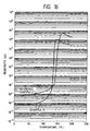
- As is apparent from comparison between Examples of Table 1 and Comparative Examples of Table 2, the samples using a conductive ceramic powder other than WC (Comparative Examples 1 to 5 except Comparative Example 3 using TiC) have an extremely high surface resistivity almost like an insulator whether the conductive powder content is increased to 30 vol% or 40 vol%. The sample of Comparative Example 3 using TiC, although added in an amount increased to 40 vol%, has as high a volume resistivity as 985 Ω•cm. To the contrary, the resistivity of those samples using WC is by far lower even when the amount of WC added is as small as 23 vol%. In Fig. 10 is shown the volume resistivity (ρ) vs. temperature (T) characteristics of the sample containing 25 vol% of WC (Example 2) and that containing 40 vol% of TiC (Comparative Example 3).
- Fig. 7 shows the p-T characteristics of Examples 1 to 4 and Comparative Example 8. As is seen from the graph of Fig. 7 and the results in Table 1, the room temperature surface resistivity exceeds 300 MΩ at a WC content of 18 vol%, which is too high for practical use. A preferred WC content for securing practical utility is 23 vol% or more, and the room temperature surface resistivity becomes lower as the WC content increases. On the other hand, the kneading torque becomes greater as the WC content increases. While not shown in Fig. 7 or Table 1, it has been proved that kneading and molding become difficult if the WC content exceeds 50 vol%. Therefore, the amount of WC to be added ranges from 20 to 50 vol%, more preferably from 23 to 50 vol%, still preferably from 25 to 40 vol%, based on the PTC composition.
- Fig 8 is a graph showing ρ-T characteristics dependent on the average particle size of WC. As is seen from the data of Examples 2, 5 to 8, and 12 and Fig. 8, the room temperature surface resistivity increases as the average particle size of WC increases. If the average particle size is too large, increase of instability of resistivity is observed. It was revealed that if the average particle size exceeds 50 µm as in Example 8, the breakdown voltage Vb becomes seriously low. In order to ensure a high breakdown voltage of 180 V or more, it is preferable that WC has an average particle size of not more than 10 µm as is apparent from the results of Examples 1 to 7. Further, as shown in Examples 1 to 4, with the WC average particle size being 1 µm or less, an increase of WC content from 25 vol% to 30 vol% results in reduction of resistivity by one or more figures and yet gives no adverse influence on the rate of resistivity change Hp or breakdown voltage Vb. Accordingly, a still preferred average particle size of WC is not greater than 1 µm.
- WC powder having an average particle size smaller than 0.1 µm is not only expensive but causes an increase in kneading torque and makes kneading difficult, so that a preferred average particle size is 0.1 µm or greater. Where the average particle size is as small as is preferred, the same performance as described above can be assured even if the kind of PVDF is altered as in Example 9 or if PVDF is replaced with other organic polymers, such as PE or EVA, as shown in Table 1 and Fig. 9. It was confirmed in these cases that an increase in WC average particle size results in the same tendencies as to breakdown voltage, resistivity, and resistivity stability as observed with PVDF.
- Fig. 11 is a graph showing p-T characteristics observed with WC in comparison with those observed with Ni or CB. As is seen from Fig. 11 and the data of Comparative Example 6, the sample using Ni powder as a conductive substance is equal to WC-containing samples in terms of initial room temperature resistivity and rate of resistivity change but has a low breakdown voltage (Vb = 130 V). The Ni-containing sample was also found inferior in heat resistance and reliability, such as repeatability. That is, as shown in Table 3, when samples were subjected to 3 thermal cycles for the measurement of ρ-T characteristics (from room temperature to 200°C), the rate of the initial room temperature volume resistivity (ρ25) to that after the thermal history was about 22% in Example 3, whereas that of Comparative Example 6 using Ni was as high as about +900% or more, indicating poor repeatability.
- In Comparative Example 7 in which CB is used as a conductive substance, the rate of change in ρ25 after 3 ρ-T cycles was about 18% as shown in Table 3, which is not so different from the result of Example 2. However, as is seen from Table 2 and Fig. 11, the CB-containing sample shows such tendencies that the initial room temperature resistivity is higher than that of the Ni- or WC-containing sample by one or more figures and that the rate of resistivity change Hp is lowered by about 4 figures. An increase in CB content in an attempt to lower the room temperature resistivity could not achieve the level of the Ni- or WC-containing samples; on the contrary a further reduction in rate of resistivity change Hp was brought about.
- A sheet of a PTC composition was prepared in the same manner as in Example 1, except for increasing the WC content to 30 vol%.
- A stainless steel-made plain weave mesh having an opening size of 200 mesh was embedded on each side of the sheet at 200°C under a load of 30 kgf/cm3. After allowing to cool to room temperature, both sides of the sheet was electroless-plated with Ni to a thickness of 1 to 2 µm. The sheet was punched into a disk having a diameter of 10 mm to obtain a PTC element.
- A PTC element was prepared in the same manner as in Example 13, except that the each surface of the sheet before Ni plating, with the mesh embedded in, was abraded with a sand paper to increase the exposed area of the mesh.
- A PTC element was prepared in the same manner as in Example 13, except that Ni electroless plating was replaced with vacuum evaporation of Cu at a chamber temperature of 160°C to form a Cu layer having a thickness of 1 to 2 µm.
- A PTC element was prepared in the same manner as in Example 15, except that the each surface of the sheet before Cu deposition, with the mesh embedded in, was abraded with a sand paper to increase the exposed area of the mesh.
- A PTC element was prepared in the same manner as in Example 15, except for changing the opening size of the mesh to 400 mesh.
- A PTC element was prepared in the same manner as in Example 15, except for replacing the mesh having an opening size of 200 mesh with a stainless steel-made mesh having an opening size of 400 mesh and having no difference in level at the intersections.
- A PTC element was prepared in the same manner as in Example 13, except that each electrode was formed only by Ni plating without using the metal mesh.
- A PTC element was prepared in the same manner as in Example 13, except that Ni plating was not conducted.
- A PTC element was prepared in the same manner as in Example 15, except that each electrode was formed only by Cu vacuum evaporation without using the metal mesh.
- Each of the PTC elements obtained in Examples 12 to 17 and Reference Examples 1 to 3 was evaluated as follows. The results obtained are shown in Table 4 and Figs. 12 through 15.
- Measured by a four-terminal method.
- An adhesive tape (T4000, produced by Sony Chemical Co., Ltd.) was adhered to the entire surface of the electrode and rapidly stripped off. The adhesion of the electrode was judged by whether or not the electrode was peeled.
- The surface resistivity-temperature (R-T) characteristics were measured in a temperature range of room temperature (25°C) to 200°C. After the measurement, the sheet was observed to see whether any deformation or development of wrinkles or cracks occurred.
Example No. Initial Resistivity (Ω) Adhesion Deformation Mesh Size Abrasion Deposition Ex. 13 0.145 not peeled not observed #200 none Ni plating Ex. 14 0.079 " " " done " Ex. 15 0.060 " " " none Cu vacuum evaporation Ex. 16 0.031 " " " done " Ex. 17 0.063 " " #400 none " Ex. 18 0.029 " " " " " Ref. Ex. 1 0.200 peeled observed - " Ni plating Ref. Ex. 2 0.675 not tested not observed #200 " none Ref. Ex. 3 0.090 not peeled observed - " Cu Vacuum evaporation - It is seen that the PTC elements whose electrodes had been formed by plating or vacuum evaporation only (Reference Examples 1 and 3) showed weak adhesion between the electrode and the PTC sheet and had a high initial resistivity. The element whose electrodes had been formed only by embedding a metal mesh (Reference Example 2) showed improvement in mechanical strength over those of Reference Examples 1 and 3 but had a high initial resistivity and was instable as shown in Fig. 16.
- On the other hand, it was proved that the electrode structure formed by embedding a metal mesh followed by plating or vacuum evaporation is effective to reduce the initial resistivity while relaxing the stress due to thermal stress thereby enhancing mechanical strength of the PTC sheet and the electrodes and preventing deformation or development of cracks, etc. (Examples 13, 15, and 17).
- These effects can further be enhanced by using a metal mesh with no difference in level at the intersections (Example 18) or abrading both the embedded metal mesh and the PTC sheet to increase the exposed area of the mesh and the conductive particles in the PTC composition (Examples 14 and 16). In these cases, the initial surface resistivity can be lowered as shown in Figs. 13 through 15.
- According to the conventional method of electrode formation as shown in Fig. 17(b), in which
plain weave mesh 2 is merely embedded inPTC sheet 1 by hot press bonding, it isonly intersections 2a of mesh wires that is exposed on the surface ofsheet 1. Therefore, the contact area between the mesh andmetal layer 3 formed thereon by plating or vacuum evaporation is limited, resulting in an increase in initial resistivity. On the other hand, in Examples according to the invention as shown in Fig. 1(b), in which embedding ofmesh 2 is followed by surface abrasion, the exposed area corresponding tointersections 2a of the mesh can be extended. As a result, the contact area withmetal layer 3 is so increased, resulting in reduction in initial resistivity. - Where the electrode consists solely of
metal layer 3 formed by plating or vacuum evaporation as shown in Fig. 18(b) (Reference Examples 1 and 3),PTC sheet 1 ormetal layer 3 tend to undergo deformation or development of wrinkles or cracks due to the difference between the PTC sheet and the metal layer in coefficient of linear expansion. It seems that embeddedmesh 2 as in Examples relaxes the stress at the openings of the mesh and also serves as a support ofmetal layer 3, producing a so-called anchor effect. The problems which might occur with the electrode formed solely ofmetal layer 3 can thus be solved. - According to the invention, in which WC is used as conductive powder to be incorporated into an organic polymer, a low resistivity can be obtained by addition of a smaller amount of the conductive powder than has been required of other conductive ceramic powders. As a result, kneading with the organic polymer and subsequent molding can be carried out easier to facilitate the production of small-sized thermistors for high-current circuits.
- Further, since conductive ceramic powder is chemically more stable than metal and harder and more resistant to heat than metal or carbon black, it provides a highly reliable thermistor having excellent mechanical strength, stable resistivity, stability of performance against repetition of thermal cycles, and a high breakdown voltage. As compared with CB-containing thermistors, the WC-containing thermistors of the invention show a lower resistivity at room temperature and a greater rate of resistivity change with temperature.
- Because of these advantages, the thermistor of the present invention are effective in uses where lower electrical resistance and higher heat resistance are demanded, for example, for prevention of overcurrent due to a shortcircuit of a charging or discharging circuit of secondary batteries, prevention of overcurrent due to lock of a motor typified by a door lock motor of automobiles, and prevention of overcurrent due to a shortcircuit of a telecommunication circuit.
- In the invention, difficulty of kneading can be avoided by using WC powder having an average particle size of not smaller than 0.1 µm, and a thermistor having a low room temperature resistivity, a large rate of resistivity change, and a high breakdown voltage can be obtained by using WC powder having an average particle size of not greater than 10 µm.
- In a preferred mode of the invention, for example, polyvinylidene fluoride, polyethylene, polypropylene, polyvinyl chloride, polyvinyl acetate, an ionomer, or a copolymer comprising monomers of these polymers is selected as an organic polymer with which WC is to be kneaded, whereby a thermistor excellent in room temperature resistivity, rate of resistivity change, breakdown voltage, repeatability, and reliability can be obtained.
- According to the invention, a thermistor having a low room temperature resistivity and a high rate of resistivity change can be obtained by adding at least 20% by volume of WC, and ease of kneading and molding can be assured to facilitate production of a thermistor by limiting the amount of WC added to 50% by volume at the most.
- In a preferred embodiment of the invention, a part of the metal mesh is exposed on the surface of the PTC composition, whereby the initial resistivity can further be lowered, and the stress due to thermal stress can be relaxed to afford mechanical reinforcement against deformation of the PTC composition or development of wrinkles or cracks in the electrode.
- In another preferred embodiment, the metal mesh used has an opening size of 200 to 600 mesh, whereby the resulting stock sheet can be punched or cut with ease and at low cost.
- In still another preferred embodiment, the metal mesh used is selected from plain weave mesh, twilled weave mesh, plain weave mesh having been squashed (flattened), twilled weave mesh having been squashed (flattened), and mesh with no difference in level at the intersections thereof, whereby a PTC element having a further reduced thickness can be prepared, the abrasion operation is easier, and the production process can be simplified.
- In a further preferred embodiment, the metal layer is formed by chemical plating, electroplating, vacuum vapor phase deposition or flame spray coating, whereby the initial resistivity can be lowered.
- In a still further preferred embodiment, the metal layer is formed on the abraded surface of the PTC composition including the embedded metal mesh, whereby the surface resistivity is stabilized and is further lowered.
- In the invention , WC is used as a conductive substance, whereby a PTC thermistor excellent in resistivity, rate of resistivity change, breakdown voltage, repetition stability of R-T characteristics, and reliability can be obtained.
- While the invention has been described in detail and with reference to specific examples thereof, it will be apparent to one skilled in the art that various changes and modifications can be made therein without departing from the scope thereof as defined in the appended claims.
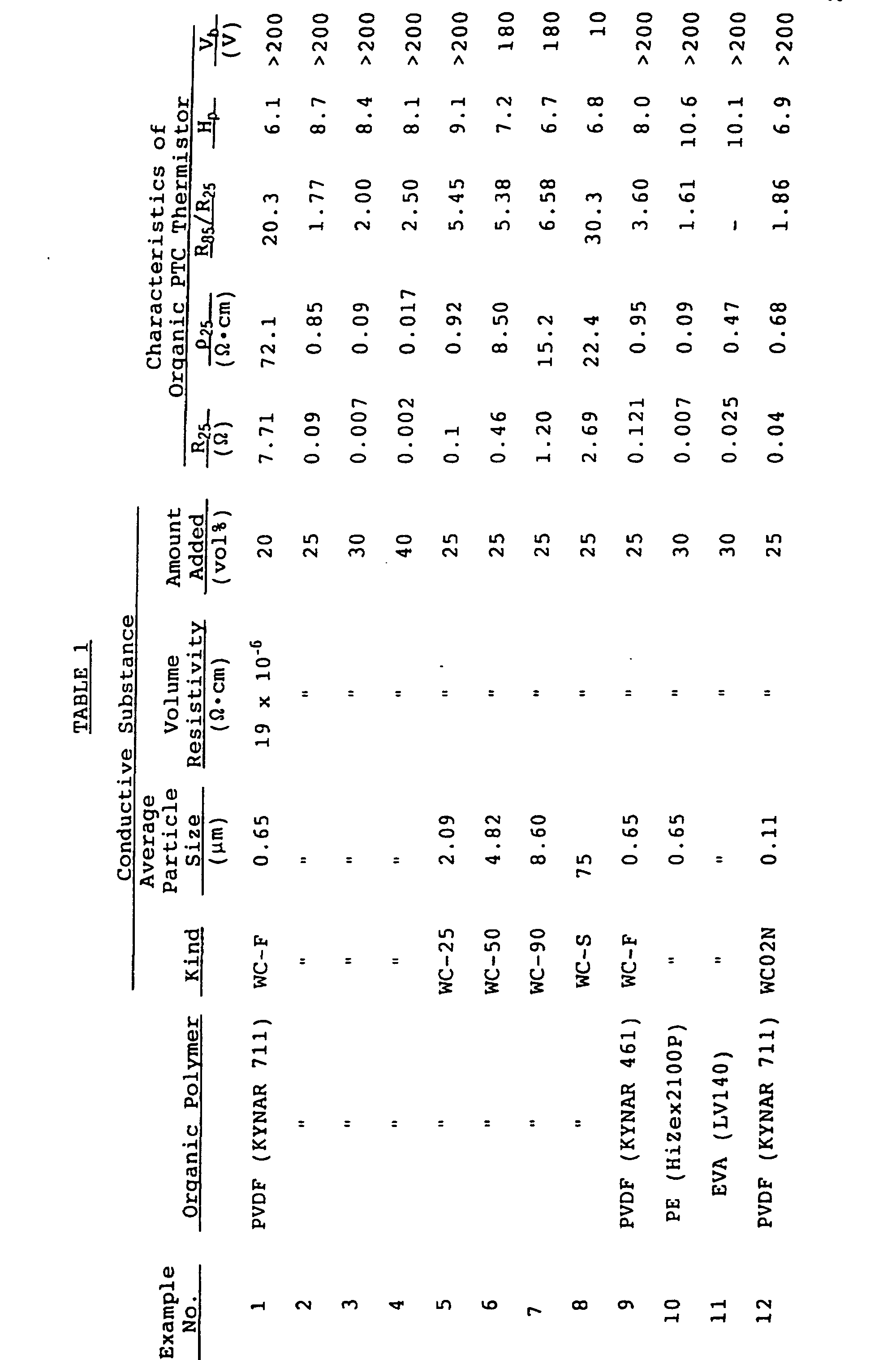

| ρ25 (Ω•cm) | |||
| Example No. | Initial | After 3 ρ-T Cycles | Rate of Change |
| (%) | |||
| Example 3 | 0.09 | 0.11 | +22.2 |
| Comparative Example 6 | 0.07 | 0.72 | +928.6 |
| Comparative Example 7 | 1.35 | 1.59 | +17.7 |
Claims (11)
- An organic PTC thermistor having a positive temperature coefficient of resistivity, which comprises a PTC composition comprising an organic polymer having dispersed therein a conductive substance, and at least one pair of electrodes,
wherein said conductive substance is tungsten carbide powder, characterized in that said tungsten carbide powder has an average particle size of 0.1 to 10 µm, and is present in an amount of 20 to 50% by volume based on the total volume of the PTC composition. - The organic PTC thermistor according to claim 1, wherein said organic polymer is at least one polymer selected from the group consisting of polyvinylidene fluoride, polyethylene, polypropylene, polyvinyl chloride, polyvinyl acetate, an ionomer, and a copolymer comprising monomers of these polymers.
- The organic PTC thermistor according to claim 1, wherein said electrodes each have a structure composed of a metal mesh and a metal layer.
- The organic PTC thermistor according to claim 3, wherein said metal mesh is embedded in the surface of said PTC composition, a part of said metal mesh being exposed.
- The organic PTC thermistor according to claim 3, wherein said metal mesh has an opening size of 200 to 600 mesh.
- The organic PTC thermistor according to claim 3, wherein said metal mesh is at least one of plain weave mesh, twilled weave mesh, plain weave mesh having been squashed, twilled weave mesh having been squashed, and mesh with no difference in level at the intersections.
- The organic PTC thermistor according to claim 3, wherein said metal layer is formed by chemical plating, electroplating, vacuum vapor phase deposition or flame spray coating.
- The organic PTC thermistor according to claim 3, wherein said metal layer is formed on an abraded surface of said PTC composition inclusive of said metal mesh.
- An apparatus for preventing abnormal overheat of a fluorescent tube comprising a fluorescent tube and an organic PTC thermistor element according to claim 1.
- The apparatus for preventing abnormal overheat of a fluorescent tube according to claim 9, wherein one electrode terminal of said thermistor element and one electrode lead of said fluorescent tube are electrically connected, and said thermistor element is integrated into a lighting circuit of said fluorescent tube with series connection.
- The apparatus for preventing abnormal overheat of a fluorescent tube according to claim 9, wherein an increase of resistivity of said thermistor due to abnormal overheat of said fluorescent tube is detected in a detecting circuit dependent of the lighting circuit of said fluorescent tube.
Applications Claiming Priority (12)
| Application Number | Priority Date | Filing Date | Title |
|---|---|---|---|
| JP189096/95 | 1995-07-25 | ||
| JP18909695A JP3229170B2 (en) | 1995-07-25 | 1995-07-25 | Fluorescent lamp abnormal overheat prevention device |
| JP18909695 | 1995-07-25 | ||
| JP273550/95 | 1995-09-27 | ||
| JP27355095 | 1995-09-27 | ||
| JP27355095 | 1995-09-27 | ||
| JP908496 | 1996-01-23 | ||
| JP9084/96 | 1996-01-23 | ||
| JP908496A JP2936057B2 (en) | 1996-01-23 | 1996-01-23 | Organic PTC thermistor |
| JP17423196 | 1996-06-13 | ||
| JP17423196A JP2810351B2 (en) | 1995-09-27 | 1996-06-13 | Organic positive temperature coefficient thermistor |
| JP174231/96 | 1996-06-13 |
Publications (3)
| Publication Number | Publication Date |
|---|---|
| EP0758131A2 EP0758131A2 (en) | 1997-02-12 |
| EP0758131A3 EP0758131A3 (en) | 1997-08-20 |
| EP0758131B1 true EP0758131B1 (en) | 2004-10-06 |
Family
ID=27455091
Family Applications (1)
| Application Number | Title | Priority Date | Filing Date |
|---|---|---|---|
| EP96111794A Expired - Lifetime EP0758131B1 (en) | 1995-07-25 | 1996-07-22 | Organic PTC thermistor |
Country Status (8)
| Country | Link |
|---|---|
| US (1) | US5793276A (en) |
| EP (1) | EP0758131B1 (en) |
| KR (1) | KR100295013B1 (en) |
| CN (1) | CN1090797C (en) |
| DE (1) | DE69633547T2 (en) |
| MY (1) | MY115034A (en) |
| NO (1) | NO318126B1 (en) |
| TW (1) | TW312794B (en) |
Families Citing this family (35)
| Publication number | Priority date | Publication date | Assignee | Title |
|---|---|---|---|---|
| TW344828B (en) * | 1997-02-28 | 1998-11-11 | Mitsubishi Electric Corp | Organic positive temperature coefficient composition and a circuit protection device using such composition |
| JP3219044B2 (en) * | 1997-03-31 | 2001-10-15 | 松下電器産業株式会社 | Ring fluorescent lamp |
| EP0932166B1 (en) * | 1998-01-22 | 2007-03-21 | Mitsubishi Denki Kabushiki Kaisha | Polymeric PTC composition and circuit protection device made therefrom |
| JP3736171B2 (en) * | 1998-03-31 | 2006-01-18 | 東芝ライテック株式会社 | Light bulb shaped fluorescent lamp and lighting fixture |
| EP1100135A4 (en) * | 1998-06-25 | 2006-06-14 | Mitsubishi Electric Corp | CELL AND METHOD FOR THE PRODUCTION THEREOF |
| JP4011636B2 (en) * | 1998-06-25 | 2007-11-21 | 三菱電機株式会社 | Battery and manufacturing method thereof |
| US6159635A (en) * | 1998-09-29 | 2000-12-12 | Electrofuel Inc. | Composite electrode including current collector |
| US20020198145A1 (en) * | 1999-06-10 | 2002-12-26 | Cognetix, Inc. | MuO-conopeptides and their use as local anesthetics |
| US6362721B1 (en) * | 1999-08-31 | 2002-03-26 | Tyco Electronics Corporation | Electrical device and assembly |
| CN1397016A (en) * | 2000-01-28 | 2003-02-12 | 催化电极有限公司 | Carbon monoxide detector |
| US6597551B2 (en) | 2000-12-13 | 2003-07-22 | Huladyne Corporation | Polymer current limiting device and method of manufacture |
| KR100411778B1 (en) * | 2001-10-12 | 2003-12-24 | 주식회사 쎄라텍 | Manufacturing method for positive temperature coefficent thermistor |
| JP3857571B2 (en) * | 2001-11-15 | 2006-12-13 | タイコ エレクトロニクス レイケム株式会社 | Polymer PTC thermistor and temperature sensor |
| TWI269317B (en) * | 2005-07-28 | 2006-12-21 | Polytronics Technology Corp | Over-current protection device |
| TWI292972B (en) * | 2005-08-11 | 2008-01-21 | Polytronics Technology Corp | Over-current protection device |
| USRE44224E1 (en) | 2005-12-27 | 2013-05-21 | Polytronics Technology Corp. | Surface-mounted over-current protection device |
| TWI282696B (en) | 2005-12-27 | 2007-06-11 | Polytronics Technology Corp | Surface-mounted over-current protection device |
| US8044763B2 (en) | 2005-12-27 | 2011-10-25 | Polytronics Technology Corp. | Surface-mounted over-current protection device |
| TWI298598B (en) * | 2006-02-15 | 2008-07-01 | Polytronics Technology Corp | Over-current protection device |
| TWI310955B (en) * | 2006-09-26 | 2009-06-11 | Polytronics Technology Corp | Over-current protection device |
| CN101162632B (en) * | 2006-10-10 | 2010-05-19 | 聚鼎科技股份有限公司 | Overcurrent protection assembly |
| US8728354B2 (en) * | 2006-11-20 | 2014-05-20 | Sabic Innovative Plastics Ip B.V. | Electrically conducting compositions |
| DE102007029525A1 (en) * | 2007-04-12 | 2008-10-23 | Metallux Ag | Composite component for use in motor vehicle industry, has electrical resistor with conductive fibers which are electrically connected with electrical connections and run at connections and in material, where connections are formed at body |
| CN102127287A (en) * | 2011-01-31 | 2011-07-20 | 上海长园维安电子线路保护股份有限公司 | Conductive composite material and PTC (Positive Temperature Coefficient) thermal sensitive element prepared from same |
| US9035337B2 (en) * | 2011-02-14 | 2015-05-19 | Semiconductor Energy Laboratory Co., Ltd. | Light-emitting module, light-emitting panel, and lighting device |
| US9295944B2 (en) | 2011-12-27 | 2016-03-29 | Toyota Jidosha Kabushiki Kaisha | Electrically heated catalyst device and its manufacturing method |
| KR20140119795A (en) * | 2012-01-30 | 2014-10-10 | 피에스티 센서스 (피티와이) 리미티드 | Large area temperature sensor |
| CN106317544B (en) * | 2015-06-30 | 2018-12-21 | 上海利韬电子有限公司 | Conductive polymer compositions, conducting polymer sheet material, electric device and their preparation method |
| US11199456B2 (en) | 2016-10-25 | 2021-12-14 | Hewlett-Packard Development Company, L.P. | Temperature sensors |
| TWI642148B (en) * | 2016-12-27 | 2018-11-21 | 日商三星皮帶股份有限公司 | Conductive paste and electronic substrate and method of manufacturing same |
| CN108885918B (en) | 2016-12-27 | 2020-05-01 | 三之星机带株式会社 | Conductive paste, electronic substrate and method for producing the same |
| TWI685011B (en) * | 2017-09-22 | 2020-02-11 | 美商力特福斯股份有限公司 | Fuse device |
| CN111226499B (en) * | 2017-10-23 | 2022-11-18 | 伊利诺斯工具制品有限公司 | High wattage solderless flexible connector for printed conductors |
| KR102742832B1 (en) * | 2020-02-25 | 2024-12-13 | 리텔퓨즈 인코퍼레이티드 | PPTC heaters and materials with stable power and self-limiting behavior |
| TWI822426B (en) * | 2022-10-28 | 2023-11-11 | 聚鼎科技股份有限公司 | Over-current protection device |
Family Cites Families (22)
| Publication number | Priority date | Publication date | Assignee | Title |
|---|---|---|---|---|
| US3591526A (en) * | 1968-01-25 | 1971-07-06 | Polyelectric Corp | Method of manufacturing a temperature sensitive,electrical resistor material |
| US3673121A (en) * | 1970-01-27 | 1972-06-27 | Texas Instruments Inc | Process for making conductive polymers and resulting compositions |
| US4237441A (en) * | 1978-12-01 | 1980-12-02 | Raychem Corporation | Low resistivity PTC compositions |
| US4369343A (en) * | 1979-11-26 | 1983-01-18 | Nissan Motor Co., Ltd. | Ignition distributor having electrodes with thermistor discharging portions |
| US4545926A (en) * | 1980-04-21 | 1985-10-08 | Raychem Corporation | Conductive polymer compositions and devices |
| US4314230A (en) * | 1980-07-31 | 1982-02-02 | Raychem Corporation | Devices comprising conductive polymers |
| DE3311051A1 (en) * | 1983-03-25 | 1984-09-27 | Siemens AG, 1000 Berlin und 8000 München | TAPE FLEXIBLE HEATING ELEMENT CONSTRUCTED FROM ELECTRICALLY CONDUCTIVE PORCELAIN FROM PTC MATERIAL AND AN ORGANIC INSULATING PLASTIC AS BINDING AGENT, AND METHOD FOR PRODUCING THE FLEXIBLE HEATING ELEMENT |
| JPS6285401A (en) * | 1985-10-09 | 1987-04-18 | 株式会社村田製作所 | Positive characteristics organic thermister |
| JPS62299833A (en) * | 1986-06-19 | 1987-12-26 | Matsushita Graphic Commun Syst Inc | Illumination light source device |
| JPH01143203A (en) * | 1987-11-27 | 1989-06-05 | Murata Mfg Co Ltd | Organic positive characteristic thermister |
| JPH01257304A (en) * | 1988-04-06 | 1989-10-13 | Murata Mfg Co Ltd | Organic positive temperature coefficient thermistor |
| JPH0616442B2 (en) * | 1988-04-06 | 1994-03-02 | 株式会社村田製作所 | Organic positive temperature coefficient thermistor |
| BE1002413A3 (en) * | 1988-05-11 | 1991-01-29 | Spoelders Ludy | Device for saw-cutting between two pairs of upper and lower blades and gluing the ends of veneer bands. |
| JP2876125B2 (en) * | 1988-09-21 | 1999-03-31 | ティーディーケイ株式会社 | Low resistance PTC element |
| JPH0651859B2 (en) * | 1989-04-04 | 1994-07-06 | 帝国通信工業株式会社 | Printed conductive paste for sliding contact pattern |
| AU637370B2 (en) * | 1989-05-18 | 1993-05-27 | Fujikura Ltd. | Ptc thermistor and manufacturing method for the same |
| DE69021708T2 (en) * | 1989-08-07 | 1996-03-21 | Mitsui Toatsu Chemicals | THIN FILM THERMISTOR WITH POSITIVE COEFFICIENT. |
| JPH047801A (en) * | 1990-04-25 | 1992-01-13 | Daito Tsushinki Kk | Ptc device |
| SE468026B (en) * | 1990-06-05 | 1992-10-19 | Asea Brown Boveri | SET TO MAKE AN ELECTRIC DEVICE |
| JP2508894B2 (en) * | 1990-06-11 | 1996-06-19 | 株式会社村田製作所 | Dielectric filter device |
| JP2833242B2 (en) * | 1991-03-12 | 1998-12-09 | 株式会社村田製作所 | NTC thermistor element |
| JPH05109502A (en) * | 1991-10-18 | 1993-04-30 | Daito Tsushinki Kk | Ptc device |
-
1996
- 1996-07-17 US US08/682,301 patent/US5793276A/en not_active Expired - Lifetime
- 1996-07-22 DE DE69633547T patent/DE69633547T2/en not_active Expired - Fee Related
- 1996-07-22 EP EP96111794A patent/EP0758131B1/en not_active Expired - Lifetime
- 1996-07-23 NO NO19963059A patent/NO318126B1/en not_active IP Right Cessation
- 1996-07-24 TW TW085109112A patent/TW312794B/zh active
- 1996-07-24 MY MYPI96003041A patent/MY115034A/en unknown
- 1996-07-25 CN CN96112244A patent/CN1090797C/en not_active Expired - Fee Related
- 1996-07-25 KR KR1019960030230A patent/KR100295013B1/en not_active Expired - Fee Related
Also Published As
| Publication number | Publication date |
|---|---|
| DE69633547D1 (en) | 2004-11-11 |
| TW312794B (en) | 1997-08-11 |
| DE69633547T2 (en) | 2005-02-03 |
| NO963059L (en) | 1997-01-27 |
| NO318126B1 (en) | 2005-02-07 |
| MY115034A (en) | 2003-03-31 |
| CN1090797C (en) | 2002-09-11 |
| EP0758131A3 (en) | 1997-08-20 |
| KR970008228A (en) | 1997-02-24 |
| KR100295013B1 (en) | 2001-11-30 |
| US5793276A (en) | 1998-08-11 |
| NO963059D0 (en) | 1996-07-23 |
| CN1150314A (en) | 1997-05-21 |
| EP0758131A2 (en) | 1997-02-12 |
Similar Documents
| Publication | Publication Date | Title |
|---|---|---|
| EP0758131B1 (en) | Organic PTC thermistor | |
| KR100388797B1 (en) | Ptc composition and ptc device comprising the same | |
| EP0853322B1 (en) | Low resistance electrical interface for current limiting polymers by plasma processing | |
| US5247276A (en) | Ptc device | |
| JP4666760B2 (en) | Electrical device using conductive polymer | |
| AU693994B2 (en) | Condition tester for a battery | |
| KR100249116B1 (en) | Battery with electrochemical tester | |
| JP2000188206A (en) | Polymer ptc composition and ptc device | |
| US6147330A (en) | PTC thermistor elements and heating devices incorporating same | |
| US4603165A (en) | Material suitable for thermal protection of electrochemical cells and other articles | |
| JPH1098829A (en) | Protective circuit employing ptc element and protective element therefor | |
| US5824436A (en) | Electrically conductive polymeric coating for an electrochemical charge storage device | |
| JP2810351B2 (en) | Organic positive temperature coefficient thermistor | |
| JPH10208902A (en) | Production of organic ptc thermistor | |
| JP2936057B2 (en) | Organic PTC thermistor | |
| JP4459438B2 (en) | Method for manufacturing an electrical device and method for manufacturing a battery assembly | |
| CN100479072C (en) | overcurrent protection element | |
| JP2970422B2 (en) | PTC element | |
| JP2007036230A (en) | Overcurrent protection element | |
| JP2001057302A (en) | Organic ptc thermistor and manufacture thereof | |
| JPH10223406A (en) | PTC composition and PTC element using the same | |
| KR960000423B1 (en) | Conductive polymer composition and its electrical device | |
| JP2006024863A (en) | Overcurrent protecting element and method of manufacturing the same | |
| EP1275273A1 (en) | Electrical device having ptc conductive polymer | |
| JPH09246010A (en) | Conductive polymer |
Legal Events
| Date | Code | Title | Description |
|---|---|---|---|
| PUAI | Public reference made under article 153(3) epc to a published international application that has entered the european phase |
Free format text: ORIGINAL CODE: 0009012 |
|
| AK | Designated contracting states |
Kind code of ref document: A2 Designated state(s): DE FR GB SE |
|
| PUAL | Search report despatched |
Free format text: ORIGINAL CODE: 0009013 |
|
| AK | Designated contracting states |
Kind code of ref document: A3 Designated state(s): DE FR GB SE |
|
| 17P | Request for examination filed |
Effective date: 19971103 |
|
| 17Q | First examination report despatched |
Effective date: 20030520 |
|
| GRAP | Despatch of communication of intention to grant a patent |
Free format text: ORIGINAL CODE: EPIDOSNIGR1 |
|
| GRAS | Grant fee paid |
Free format text: ORIGINAL CODE: EPIDOSNIGR3 |
|
| GRAA | (expected) grant |
Free format text: ORIGINAL CODE: 0009210 |
|
| AK | Designated contracting states |
Kind code of ref document: B1 Designated state(s): DE FR GB SE |
|
| REG | Reference to a national code |
Ref country code: GB Ref legal event code: FG4D |
|
| REF | Corresponds to: |
Ref document number: 69633547 Country of ref document: DE Date of ref document: 20041111 Kind code of ref document: P |
|
| PG25 | Lapsed in a contracting state [announced via postgrant information from national office to epo] |
Ref country code: SE Free format text: LAPSE BECAUSE OF FAILURE TO SUBMIT A TRANSLATION OF THE DESCRIPTION OR TO PAY THE FEE WITHIN THE PRESCRIBED TIME-LIMIT Effective date: 20050106 |
|
| PLBE | No opposition filed within time limit |
Free format text: ORIGINAL CODE: 0009261 |
|
| STAA | Information on the status of an ep patent application or granted ep patent |
Free format text: STATUS: NO OPPOSITION FILED WITHIN TIME LIMIT |
|
| ET | Fr: translation filed | ||
| 26N | No opposition filed |
Effective date: 20050707 |
|
| PGFP | Annual fee paid to national office [announced via postgrant information from national office to epo] |
Ref country code: GB Payment date: 20060719 Year of fee payment: 11 Ref country code: FR Payment date: 20060719 Year of fee payment: 11 |
|
| GBPC | Gb: european patent ceased through non-payment of renewal fee |
Effective date: 20070722 |
|
| PG25 | Lapsed in a contracting state [announced via postgrant information from national office to epo] |
Ref country code: GB Free format text: LAPSE BECAUSE OF NON-PAYMENT OF DUE FEES Effective date: 20070722 |
|
| REG | Reference to a national code |
Ref country code: FR Ref legal event code: ST Effective date: 20080331 |
|
| PG25 | Lapsed in a contracting state [announced via postgrant information from national office to epo] |
Ref country code: FR Free format text: LAPSE BECAUSE OF NON-PAYMENT OF DUE FEES Effective date: 20070731 |
|
| PGFP | Annual fee paid to national office [announced via postgrant information from national office to epo] |
Ref country code: DE Payment date: 20090716 Year of fee payment: 14 |
|
| PG25 | Lapsed in a contracting state [announced via postgrant information from national office to epo] |
Ref country code: DE Free format text: LAPSE BECAUSE OF NON-PAYMENT OF DUE FEES Effective date: 20110201 |
|
| REG | Reference to a national code |
Ref country code: DE Ref legal event code: R119 Ref document number: 69633547 Country of ref document: DE Effective date: 20110201 |