EP0757662B1 - Making porous mineral fibers - Google Patents
Making porous mineral fibers Download PDFInfo
- Publication number
- EP0757662B1 EP0757662B1 EP95916336A EP95916336A EP0757662B1 EP 0757662 B1 EP0757662 B1 EP 0757662B1 EP 95916336 A EP95916336 A EP 95916336A EP 95916336 A EP95916336 A EP 95916336A EP 0757662 B1 EP0757662 B1 EP 0757662B1
- Authority
- EP
- European Patent Office
- Prior art keywords
- mineral
- molten
- fibers
- molten mineral
- mass
- Prior art date
- Legal status (The legal status is an assumption and is not a legal conclusion. Google has not performed a legal analysis and makes no representation as to the accuracy of the status listed.)
- Expired - Lifetime
Links
- 239000002557 mineral fiber Substances 0.000 title claims abstract description 27
- 229910052500 inorganic mineral Inorganic materials 0.000 claims abstract description 73
- 239000011707 mineral Substances 0.000 claims abstract description 73
- 239000000463 material Substances 0.000 claims abstract description 42
- XLYOFNOQVPJJNP-UHFFFAOYSA-N water Substances O XLYOFNOQVPJJNP-UHFFFAOYSA-N 0.000 claims abstract description 11
- 238000000034 method Methods 0.000 claims description 23
- 238000002844 melting Methods 0.000 claims description 13
- 230000008018 melting Effects 0.000 claims description 11
- 238000003756 stirring Methods 0.000 claims description 6
- 239000003365 glass fiber Substances 0.000 abstract description 11
- 238000010438 heat treatment Methods 0.000 abstract description 6
- 239000006063 cullet Substances 0.000 abstract description 4
- 239000007789 gas Substances 0.000 description 14
- 239000000835 fiber Substances 0.000 description 12
- 239000011521 glass Substances 0.000 description 12
- 238000004519 manufacturing process Methods 0.000 description 7
- 238000001816 cooling Methods 0.000 description 5
- 239000011248 coating agent Substances 0.000 description 4
- 238000000576 coating method Methods 0.000 description 4
- BASFCYQUMIYNBI-UHFFFAOYSA-N platinum Chemical compound [Pt] BASFCYQUMIYNBI-UHFFFAOYSA-N 0.000 description 4
- 230000007797 corrosion Effects 0.000 description 3
- 238000005260 corrosion Methods 0.000 description 3
- XKRFYHLGVUSROY-UHFFFAOYSA-N Argon Chemical compound [Ar] XKRFYHLGVUSROY-UHFFFAOYSA-N 0.000 description 2
- IJGRMHOSHXDMSA-UHFFFAOYSA-N Atomic nitrogen Chemical compound N#N IJGRMHOSHXDMSA-UHFFFAOYSA-N 0.000 description 2
- ZOKXTWBITQBERF-UHFFFAOYSA-N Molybdenum Chemical compound [Mo] ZOKXTWBITQBERF-UHFFFAOYSA-N 0.000 description 2
- 229910000831 Steel Inorganic materials 0.000 description 2
- RAHZWNYVWXNFOC-UHFFFAOYSA-N Sulphur dioxide Chemical compound O=S=O RAHZWNYVWXNFOC-UHFFFAOYSA-N 0.000 description 2
- 239000011230 binding agent Substances 0.000 description 2
- 230000015572 biosynthetic process Effects 0.000 description 2
- 238000011161 development Methods 0.000 description 2
- 230000018109 developmental process Effects 0.000 description 2
- 239000011152 fibreglass Substances 0.000 description 2
- 238000009775 high-speed stirring Methods 0.000 description 2
- 238000002156 mixing Methods 0.000 description 2
- 229910052750 molybdenum Inorganic materials 0.000 description 2
- 239000011733 molybdenum Substances 0.000 description 2
- 229910052697 platinum Inorganic materials 0.000 description 2
- 238000012545 processing Methods 0.000 description 2
- 239000010959 steel Substances 0.000 description 2
- 239000000654 additive Substances 0.000 description 1
- 230000000996 additive effect Effects 0.000 description 1
- 229910052786 argon Inorganic materials 0.000 description 1
- 150000004649 carbonic acid derivatives Chemical class 0.000 description 1
- 238000006243 chemical reaction Methods 0.000 description 1
- 238000004891 communication Methods 0.000 description 1
- 238000007796 conventional method Methods 0.000 description 1
- 239000000498 cooling water Substances 0.000 description 1
- 239000006185 dispersion Substances 0.000 description 1
- 230000009977 dual effect Effects 0.000 description 1
- 230000008030 elimination Effects 0.000 description 1
- 238000003379 elimination reaction Methods 0.000 description 1
- 238000007380 fibre production Methods 0.000 description 1
- 239000012530 fluid Substances 0.000 description 1
- 239000006066 glass batch Substances 0.000 description 1
- 238000005816 glass manufacturing process Methods 0.000 description 1
- 239000000156 glass melt Substances 0.000 description 1
- 239000001307 helium Substances 0.000 description 1
- 229910052734 helium Inorganic materials 0.000 description 1
- SWQJXJOGLNCZEY-UHFFFAOYSA-N helium atom Chemical compound [He] SWQJXJOGLNCZEY-UHFFFAOYSA-N 0.000 description 1
- 239000012510 hollow fiber Substances 0.000 description 1
- 239000012535 impurity Substances 0.000 description 1
- 238000009413 insulation Methods 0.000 description 1
- 239000000155 melt Substances 0.000 description 1
- 239000000203 mixture Substances 0.000 description 1
- 238000012986 modification Methods 0.000 description 1
- 230000004048 modification Effects 0.000 description 1
- 239000006060 molten glass Substances 0.000 description 1
- 229910052757 nitrogen Inorganic materials 0.000 description 1
- 230000003287 optical effect Effects 0.000 description 1
- 239000007921 spray Substances 0.000 description 1
- 230000003068 static effect Effects 0.000 description 1
- 230000035882 stress Effects 0.000 description 1
- 239000000126 substance Substances 0.000 description 1
- 229940044609 sulfur dioxide Drugs 0.000 description 1
- 235000010269 sulphur dioxide Nutrition 0.000 description 1
- 230000008646 thermal stress Effects 0.000 description 1
- 239000013585 weight reducing agent Substances 0.000 description 1
Images
Classifications
-
- C—CHEMISTRY; METALLURGY
- C03—GLASS; MINERAL OR SLAG WOOL
- C03B—MANUFACTURE, SHAPING, OR SUPPLEMENTARY PROCESSES
- C03B5/00—Melting in furnaces; Furnaces so far as specially adapted for glass manufacture
- C03B5/02—Melting in furnaces; Furnaces so far as specially adapted for glass manufacture in electric furnaces, e.g. by dielectric heating
- C03B5/027—Melting in furnaces; Furnaces so far as specially adapted for glass manufacture in electric furnaces, e.g. by dielectric heating by passing an electric current between electrodes immersed in the glass bath, i.e. by direct resistance heating
- C03B5/0275—Shaft furnaces
-
- B—PERFORMING OPERATIONS; TRANSPORTING
- B01—PHYSICAL OR CHEMICAL PROCESSES OR APPARATUS IN GENERAL
- B01F—MIXING, e.g. DISSOLVING, EMULSIFYING OR DISPERSING
- B01F35/00—Accessories for mixers; Auxiliary operations or auxiliary devices; Parts or details of general application
- B01F35/90—Heating or cooling systems
- B01F35/95—Heating or cooling systems using heated or cooled stirrers
-
- C—CHEMISTRY; METALLURGY
- C03—GLASS; MINERAL OR SLAG WOOL
- C03B—MANUFACTURE, SHAPING, OR SUPPLEMENTARY PROCESSES
- C03B3/00—Charging the melting furnaces
-
- C—CHEMISTRY; METALLURGY
- C03—GLASS; MINERAL OR SLAG WOOL
- C03B—MANUFACTURE, SHAPING, OR SUPPLEMENTARY PROCESSES
- C03B37/00—Manufacture or treatment of flakes, fibres, or filaments from softened glass, minerals, or slags
- C03B37/01—Manufacture of glass fibres or filaments
- C03B37/04—Manufacture of glass fibres or filaments by using centrifugal force, e.g. spinning through radial orifices; Construction of the spinner cups therefor
-
- C—CHEMISTRY; METALLURGY
- C03—GLASS; MINERAL OR SLAG WOOL
- C03B—MANUFACTURE, SHAPING, OR SUPPLEMENTARY PROCESSES
- C03B37/00—Manufacture or treatment of flakes, fibres, or filaments from softened glass, minerals, or slags
- C03B37/075—Manufacture of non-optical fibres or filaments consisting of different sorts of glass or characterised by shape, e.g. undulated fibres
- C03B37/0756—Hollow fibres
-
- C—CHEMISTRY; METALLURGY
- C03—GLASS; MINERAL OR SLAG WOOL
- C03B—MANUFACTURE, SHAPING, OR SUPPLEMENTARY PROCESSES
- C03B37/00—Manufacture or treatment of flakes, fibres, or filaments from softened glass, minerals, or slags
- C03B37/08—Bushings, e.g. construction, bushing reinforcement means; Spinnerettes; Nozzles; Nozzle plates
-
- C—CHEMISTRY; METALLURGY
- C03—GLASS; MINERAL OR SLAG WOOL
- C03B—MANUFACTURE, SHAPING, OR SUPPLEMENTARY PROCESSES
- C03B37/00—Manufacture or treatment of flakes, fibres, or filaments from softened glass, minerals, or slags
- C03B37/10—Non-chemical treatment
-
- C—CHEMISTRY; METALLURGY
- C03—GLASS; MINERAL OR SLAG WOOL
- C03B—MANUFACTURE, SHAPING, OR SUPPLEMENTARY PROCESSES
- C03B5/00—Melting in furnaces; Furnaces so far as specially adapted for glass manufacture
- C03B5/16—Special features of the melting process; Auxiliary means specially adapted for glass-melting furnaces
- C03B5/18—Stirring devices; Homogenisation
- C03B5/187—Stirring devices; Homogenisation with moving elements
-
- B—PERFORMING OPERATIONS; TRANSPORTING
- B01—PHYSICAL OR CHEMICAL PROCESSES OR APPARATUS IN GENERAL
- B01F—MIXING, e.g. DISSOLVING, EMULSIFYING OR DISPERSING
- B01F35/00—Accessories for mixers; Auxiliary operations or auxiliary devices; Parts or details of general application
- B01F35/90—Heating or cooling systems
- B01F2035/98—Cooling
-
- B—PERFORMING OPERATIONS; TRANSPORTING
- B01—PHYSICAL OR CHEMICAL PROCESSES OR APPARATUS IN GENERAL
- B01F—MIXING, e.g. DISSOLVING, EMULSIFYING OR DISPERSING
- B01F27/00—Mixers with rotary stirring devices in fixed receptacles; Kneaders
- B01F27/80—Mixers with rotary stirring devices in fixed receptacles; Kneaders with stirrers rotating about a substantially vertical axis
-
- Y—GENERAL TAGGING OF NEW TECHNOLOGICAL DEVELOPMENTS; GENERAL TAGGING OF CROSS-SECTIONAL TECHNOLOGIES SPANNING OVER SEVERAL SECTIONS OF THE IPC; TECHNICAL SUBJECTS COVERED BY FORMER USPC CROSS-REFERENCE ART COLLECTIONS [XRACs] AND DIGESTS
- Y02—TECHNOLOGIES OR APPLICATIONS FOR MITIGATION OR ADAPTATION AGAINST CLIMATE CHANGE
- Y02P—CLIMATE CHANGE MITIGATION TECHNOLOGIES IN THE PRODUCTION OR PROCESSING OF GOODS
- Y02P40/00—Technologies relating to the processing of minerals
- Y02P40/50—Glass production, e.g. reusing waste heat during processing or shaping
Definitions
- This invention relates to a method for making mineral fibers having gaseous occlusions according to the preamble of claim 1, which is based upon US-A-5 100 453.
- Methods and apparatus for producing mineral fibers such as glass fibers generally include a first step of melting mineral material in a large gas-fired and electrically heated tank. Smaller melters having dual heating elements are also used and generally include a cold top batch blanket. Electric melters having cold top batch blankets generally have a short life due to thermal stress and consumption of electrodes by corrosive elements of the molten mineral bath.
- High-speed stirring necessarily results in the development of a large number of gaseous occlusions in the melted mineral material.
- Gaseous occlusions result from the turbulent mixing of air and also from the formation of steam when water in the mineral batch is converted into steam.
- gaseous occlusions may be created by injecting other gases or gasifying products such as carbonates, sulfurdioxide, helium, nitrogen, or argon.
- An impeller mixes the glass bath and gases to form melted glass having gaseous occlusions of up to 50% by volume.
- the occluded melted glass is then supplied to a glass fiber forming process to form glass fibers having gaseous occlusions of between 1% and 10% by volume.
- the present invention relates to a method for making mineral fibers of heat-softenable mineral material at a high rate of throughput wherein the heat-softenable material is made by: melting the heat-softenable mineral material in a vessel; stirring the heat-softenable mineral material during said melting step to form a molten mineral mass having gaseous occlusions; feeding additional heat-softenable mineral material on top of the molten mineral mass inside the vessel; removing from the vessel a portion of the molten mineral mass having gaseous occlusions of up to 50% by volume; and fiberizing the molten mineral material after said removal step to provide mineral fibers having gaseous occlusions of greater than 1% by volume.
- the fiberizing step is performed in a rotary fiberizing spinner.
- An impeller performs the stirring step and has a drive shaft which is disposed within the molten mineral mass, and water is utilized to cool the impeller, preferably by the water cooling blades of the impeller.
- gas is preferably injected into the molten mineral mass, and the mineral fibers are made with gaseous occlusions of less than 10% by volume.
- the molten mineral mass includes a large quantity of minuscule gaseous occlusions as it is fed from the melter to the fiberizing bushing.
- the fiberizing bushing is preferably a rotary fiberizing bushing which centrifuges the molten mineral mass through small orifices in the bushing.
- the molten mineral mass is extruded through the orifices and formed into mineral fibers as it is cooled after exiting the bushing.
- the melter preferably feeds molten mineral material into a channel which supplies molten mineral material to a plurality of rotary fiberizing bushings.
- the impeller is preferably a steel impeller provided with a water-cooling system which operates with a coating of solidified molten mineral material on its surface which protects the surface from corrosion and wear.
- the apparatus utilized includes a vessel including electrodes for Joule heating and an impeller for stirring heat-softenable material to form a molten mineral mass.
- the outlet port of the vessel is in fluid flow communication with a rotary fiberizing bushing.
- the rotary fiberizing bushing acts upon molten mineral material including gaseous occlusions as received from the vessel and forms hollow mineral fibers.
- the apparatus also includes a water-cooled impeller which is protected by a coating of solidified molten mineral material.
- the impeller is isolated from electrical conduction by means of the solidified mineral material layer which also protects the impeller from corrosion and wear.
- the electrodes in the vessel are preferably disposed in the lower portion of the vessel so that they are'not directly exposed to steam or other corrosive gases in the melt.
- the electrodes may be formed of platinum or other another material which is not subject to attack by water or steam in the molten mineral mass.
- the electrode may also be protected by using inert or reducing gases to form the bubbles.
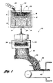
- a mineral fiber-forming apparatus is generally indicated by reference numeral 10.
- a vessel 12 having electrodes 14 and an impeller 16 is provided for melting and containing a molten mineral mass 18.
- Batch 20 including heat-softenable mineral material, such as cullet, and water is supplied to the top of the vessel 12.
- the batch 20 may also include intermixed recycled organically-coated glass fiber scrap.
- the glass fiber scrap may be supplied either separately or intermixed with the cullet or may be supplied intermittently to control the relative proportions of cullet and coated glass fiber scrap.
- the heat-softenable mineral material is heated by the electrodes 14.
- Impeller 16 disperses batch 20 in molten mineral mass 18. Air, steam and other gases are released as a result of melting the batch 20 while stirring with the impeller 16.
- the lower region "B" of the vessel 12 houses the electrodes 14 which may be formed of molybdenum, platinum or other suitable materials. If molybdenum electrodes are used it is important that they be isolated from any steam or corrosive gases in the molten mineral mass 18 since steam or corrosive gases may react with the electrodes causing corrosion. Small seeds remain in the molten mineral mass in the lower portion of the vessel B.
- the molten mineral mass 18 includes many small seeds and gaseous occlusions as it is fed through the outlet port 24.
- Molten mineral received from the vessel 12 though the outlet port 24 is supplied to a fiber forming process.
- molten mineral material may be supplied either directly to a spinner 30 or via a channel which may feed multiple spinners to form fibers 32 as the molten mineral mass is centrifuged through orifices 34 in the spinner 30.
- Other fiberizing techniques may be used with the occluded glass melt of this invention.
- Fibers 32 are deposited in a chute 36.
- Binder spray nozzles 38 are preferably provided on the chute 34 which coats the fibers with an organic binder coating which causes the fibers 32 to form a mat.
- the fibers 32 are then collected on a conveyor 40 and further processed by conventional techniques.
- the impeller 16 is preferably formed from steel and includes a water cooling conduit 42 which extends down the shaft 44 and into the blades 46 of the impeller.
- the water cooling conduit 42 receives cooling water causing the impeller 16 to be maintained at a cooler temperature than the molten mineral mass 18.
- the cool temperature of the impeller causes a portion of molten mineral mass 18 to freeze on the surface of the impeller. This coating of frozen molten mineral mass 18 protects the impeller from wear and insulates the impeller from the Joule heating circuit provided by the electrodes 14.
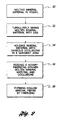
- the process of the present invention is shown in flow chart form.
- the first step in the process shown at 50 is melting the heat-softenable mineral material in the vessel 12.
- the impeller 16 is actuated to turbulently mix the molten mineral material 18.
- Additional batch 20 is supplied to the vessel causing dispersion of batch 20 in the vessel 12 and conversion of any water in the batch 20 to steam and other impurities to gas and seeds.
- the turbulent mixing of the glass bath with the impeller results in the formation of a melted glass having gaseous occlusions of up to 50% by volume of the glass bath.
- This occluded melted glass is supplied through a settling cone or device to the rotary spinner 30 to form glass fibers having gaseous occlusions of between 1% and 10% by volume.
- the molten mineral mass 18 is held in the vessel and allowed to pass into a relatively quiescent zone "B" in the lower portion of the vessel where larger seeds and gas bubbles rise as represented by reference numeral 54.
- the molten mineral material is then sent to a rotary fiberizing spinner even though it includes many minuscule gaseous occlusions and seeds.
- the rotary fiberizing spinner forms hollow mineral fibers 60 as a result of the centrifuging of the molten mineral material including gaseous occlusions and small seeds through the rotary fiberizing spinner.
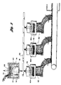
- FIG. 3 an alternative embodiment of the present invention is illustrated schematically, wherein several spinners 60a, 60b and 60c are used to form mineral fibers 62.
- Each spinner 60a-60c receives molten mineral material from the melter 64 through a channel 66.
- the melter 64 has an impeller 68 which mixes batch 70 into the molten mineral material 72 contained in vessel 74.
- the vessel 74 is heated by Joule heating by the electrodes 76.
- Each spinner 60a-60c forms the fibers 62 as previously described.
Landscapes
- Chemical & Material Sciences (AREA)
- Engineering & Computer Science (AREA)
- Organic Chemistry (AREA)
- Materials Engineering (AREA)
- General Life Sciences & Earth Sciences (AREA)
- Life Sciences & Earth Sciences (AREA)
- Geochemistry & Mineralogy (AREA)
- Manufacturing & Machinery (AREA)
- Chemical Kinetics & Catalysis (AREA)
- Electrochemistry (AREA)
- Manufacture, Treatment Of Glass Fibers (AREA)
- Artificial Filaments (AREA)
- Inorganic Fibers (AREA)
Abstract
Description
Claims (7)
- A method for making mineral fibers of heat-softenable mineral material comprising:melting the heat-softenable mineral material in a vessel;stirring the heat-softenable mineral material during said melting step to form a molten mineral mass having gaseous occlusions;feeding additional heat-softenable mineral material on top of the molten mineral mass inside the vessel; characterized byremoving from the vessel a portion of the molten mineral mass having gaseous occlusions of up to 50% by volume; andfiberizing the molten mineral material after said removal step to provide mineral fibers having gaseous occlusions of greater than 1% by volume.
- The method for making mineral fibers of claim 1 wherein said fiberizing step is performed in a rotary fiberizing spinner.
- The method for making mineral fibers of claim 1 wherein an impeller performs said stirring step and has a drive shaft which is disposed within the molten mineral mass.
- The method for making mineral fibers of claim 3 wherein water is utilized to cool the impeller.
- The method for making mineral fibers of claim 4 wherein the water cools blades of the impeller.
- The method for making mineral fibers of claim 1 wherein gas is injected into the molten mineral mass.
- The method for making mineral fibers of claim 1 wherein the mineral fibers are made with gaseous occlusions of less than 10% by volume.
Applications Claiming Priority (3)
| Application Number | Priority Date | Filing Date | Title |
|---|---|---|---|
| US234685 | 1994-04-28 | ||
| US08/234,685 US5529594A (en) | 1994-04-28 | 1994-04-28 | Method for producing mineral fibers having gaseous occlusions |
| PCT/US1995/004499 WO1995029879A1 (en) | 1994-04-28 | 1995-04-17 | Making porous mineral fibers |
Publications (3)
| Publication Number | Publication Date |
|---|---|
| EP0757662A1 EP0757662A1 (en) | 1997-02-12 |
| EP0757662A4 EP0757662A4 (en) | 1998-10-21 |
| EP0757662B1 true EP0757662B1 (en) | 2000-03-01 |
Family
ID=22882380
Family Applications (1)
| Application Number | Title | Priority Date | Filing Date |
|---|---|---|---|
| EP95916336A Expired - Lifetime EP0757662B1 (en) | 1994-04-28 | 1995-04-17 | Making porous mineral fibers |
Country Status (7)
| Country | Link |
|---|---|
| US (1) | US5529594A (en) |
| EP (1) | EP0757662B1 (en) |
| AT (1) | ATE190048T1 (en) |
| AU (1) | AU2374995A (en) |
| CA (1) | CA2188578A1 (en) |
| DE (1) | DE69515300T2 (en) |
| WO (1) | WO1995029879A1 (en) |
Families Citing this family (9)
| Publication number | Priority date | Publication date | Assignee | Title |
|---|---|---|---|---|
| JP3173336B2 (en) * | 1995-07-12 | 2001-06-04 | 日東紡績株式会社 | High strength rock wool and method for producing the same |
| US5674307A (en) * | 1995-12-12 | 1997-10-07 | Owens-Corning Fiberglas Technology, Inc. | Hollow mineral fibers using rotary process |
| CN1234784A (en) * | 1997-07-22 | 1999-11-10 | 伊索福圣戈班公司 | Glass furnaces and equipment containing glass furnaces |
| US5961686A (en) | 1997-08-25 | 1999-10-05 | Guardian Fiberglass, Inc. | Side-discharge melter for use in the manufacture of fiberglass |
| FR2774085B3 (en) * | 1998-01-26 | 2000-02-25 | Saint Gobain Vitrage | PROCESS FOR MELTING AND REFINING VITRIFIABLE MATERIALS |
| US7648933B2 (en) * | 2006-01-13 | 2010-01-19 | Dynamic Abrasives Llc | Composition comprising spinel crystals, glass, and calcium iron silicate |
| US9032760B2 (en) * | 2012-07-03 | 2015-05-19 | Johns Manville | Process of using a submerged combustion melter to produce hollow glass fiber or solid glass fiber having entrained bubbles, and burners and systems to make such fibers |
| JP5699677B2 (en) * | 2011-02-23 | 2015-04-15 | 旭硝子株式会社 | Glass melt stirring device |
| CN107651857B (en) * | 2017-09-08 | 2020-06-26 | 山西太钢不锈钢股份有限公司 | Process for quickly dissolving silica sand and bauxite in slag liquid |
Family Cites Families (24)
| Publication number | Priority date | Publication date | Assignee | Title |
|---|---|---|---|---|
| US2261022A (en) * | 1937-12-24 | 1941-10-28 | Pittsburgh Plate Glass Co | Manufacture of vesicular glass |
| NL273584A (en) * | 1955-02-28 | |||
| BE556660A (en) * | 1956-04-23 | 1900-01-01 | ||
| US3250602A (en) * | 1961-12-08 | 1966-05-10 | Owens Corning Fiberglass Corp | Method for continuously wrapping formed filaments of a rotor about an internal core |
| US3238029A (en) * | 1962-05-25 | 1966-03-01 | Insulwool Products Proprietary | Spinner for producing mineral fibers |
| US3393986A (en) * | 1965-05-28 | 1968-07-23 | Miles S. Firnhaber | Apparatus for manufacturing mineral fibers |
| US3596319A (en) * | 1968-07-22 | 1971-08-03 | Du Pont | Foam filament cutter |
| US3622293A (en) * | 1968-12-10 | 1971-11-23 | Miles S Firnhaber | Apparatus for manufacturing glass fibers |
| US3628937A (en) * | 1970-08-05 | 1971-12-21 | Lawrence A Schott | Apparatus for making foamed glass panels |
| US3929440A (en) * | 1973-11-30 | 1975-12-30 | Gen Electric Co Ltd | Manufacture of laser glass |
| US3951635A (en) * | 1974-11-29 | 1976-04-20 | Owens-Illinois, Inc. | Method for rapidly melting and refining glass |
| DE2555899C2 (en) * | 1975-12-12 | 1987-04-30 | OKALUX Kapillarglas GmbH, 8772 Marktheidenfeld | Process for producing hollow fibres from inorganic meltable materials and device for carrying out the process |
| US4309204A (en) * | 1979-11-19 | 1982-01-05 | Owens-Corning Fiberglas Corporation | Process and apparatus for remelting scrap glass |
| US4263033A (en) * | 1979-12-26 | 1981-04-21 | Owens-Corning Fiberglas Corporation | Method and apparatus for collecting mineral fibers |
| US4270943A (en) * | 1979-12-31 | 1981-06-02 | Owens-Corning Fiberglas Corporation | Rotary fiber forming spinner |
| US4361624A (en) * | 1981-01-22 | 1982-11-30 | Pq Corporation | Spray-dried hollow fibers |
| US4432780A (en) * | 1982-08-27 | 1984-02-21 | Owens-Corning Fiberglas Corporation | Glass fiber scrap reclamation |
| US4511383A (en) * | 1983-07-14 | 1985-04-16 | Owens-Corning Fiberglas Corporation | Method for producing glass fiber |
| US4518408A (en) * | 1983-07-14 | 1985-05-21 | Owens-Corning Fiberglas Corporation | Method for producing glass fiber |
| US4526597A (en) * | 1984-08-23 | 1985-07-02 | Owens-Corning Fiberglas Corporation | Gas injection in fiber forming |
| US7108808B1 (en) * | 1990-04-18 | 2006-09-19 | Stir-Melter, Inc. | Method for waste vitrification |
| US5100453A (en) * | 1991-03-07 | 1992-03-31 | Glasstech, Inc. | Method for recycling scrap mineral fibers |
| US5120342A (en) * | 1991-03-07 | 1992-06-09 | Glasstech, Inc. | High shear mixer and glass melting apparatus |
| US5352258A (en) * | 1993-03-31 | 1994-10-04 | Ppg Industries, Inc. | Production of glass fibers from scrap glass fibers |
-
1994
- 1994-04-28 US US08/234,685 patent/US5529594A/en not_active Expired - Lifetime
-
1995
- 1995-04-17 AU AU23749/95A patent/AU2374995A/en not_active Abandoned
- 1995-04-17 WO PCT/US1995/004499 patent/WO1995029879A1/en not_active Ceased
- 1995-04-17 CA CA002188578A patent/CA2188578A1/en not_active Abandoned
- 1995-04-17 AT AT95916336T patent/ATE190048T1/en not_active IP Right Cessation
- 1995-04-17 EP EP95916336A patent/EP0757662B1/en not_active Expired - Lifetime
- 1995-04-17 DE DE69515300T patent/DE69515300T2/en not_active Expired - Fee Related
Also Published As
| Publication number | Publication date |
|---|---|
| CA2188578A1 (en) | 1995-11-09 |
| ATE190048T1 (en) | 2000-03-15 |
| WO1995029879A1 (en) | 1995-11-09 |
| DE69515300D1 (en) | 2000-04-06 |
| DE69515300T2 (en) | 2000-10-26 |
| US5529594A (en) | 1996-06-25 |
| EP0757662A1 (en) | 1997-02-12 |
| AU2374995A (en) | 1995-11-29 |
| EP0757662A4 (en) | 1998-10-21 |
Similar Documents
| Publication | Publication Date | Title |
|---|---|---|
| US7565819B2 (en) | Method and device for melting and refining materials capable of being vitrified | |
| CA2245357C (en) | Side-discharge melter for use in the manufacture of fiberglass, and corresponding method | |
| JP5249671B2 (en) | Method for adjusting foam generated in vacuum clarification | |
| US7624595B2 (en) | Method and device for melting and refining materials capable of being vitrified | |
| US6125658A (en) | Glass furnace and installation comprising same | |
| US5529594A (en) | Method for producing mineral fibers having gaseous occlusions | |
| US3837823A (en) | Bushing block assembly and screen | |
| EP0432193A1 (en) | A method and an apparatus for producing mineral wool | |
| CA2105578A1 (en) | Method and apparatus for recycling scrap mineral fibers | |
| US4504302A (en) | Homogenizing apparatus glass making furnace and method of homogenizing glass | |
| EP0115509B1 (en) | Melting furnaces | |
| US20110146351A1 (en) | Method and apparatus for directly forming continuous glass filaments | |
| US4146375A (en) | Method for the continuous production of glass fiber strand | |
| US5236484A (en) | Method of firing glass-melting furnace | |
| US1874799A (en) | Method and apparatus for feeding and melting glass batch | |
| US4713106A (en) | Method and apparatus for conveying molten material | |
| US4638490A (en) | Melting furnaces | |
| SE463311B (en) | PROCEDURE AND DEVICE CONTROLING THE CONTINUOUS SUPPLY OF PORTABLE MATERIAL TO A FIBER PRODUCTION DEVICE | |
| DE69209535T2 (en) | Method and device for producing mineral fibers | |
| US4738701A (en) | Method and apparatus for forming glass fibers | |
| WO1983004245A1 (en) | Homogenizing apparatus and glass making furnace | |
| US5928401A (en) | Process of making fibers with a rotary ring furnace above a circular forehearth | |
| RU2033977C1 (en) | Glassmelter | |
| EP0963357A1 (en) | Process and apparatus for producing streams of molten glass | |
| JPH0139971B2 (en) |
Legal Events
| Date | Code | Title | Description |
|---|---|---|---|
| PUAI | Public reference made under article 153(3) epc to a published international application that has entered the european phase |
Free format text: ORIGINAL CODE: 0009012 |
|
| 17P | Request for examination filed |
Effective date: 19961004 |
|
| AK | Designated contracting states |
Kind code of ref document: A1 Designated state(s): AT BE CH DE DK ES FR GB GR IE IT LI LU MC NL PT SE |
|
| A4 | Supplementary search report drawn up and despatched |
Effective date: 19980904 |
|
| AK | Designated contracting states |
Kind code of ref document: A4 Designated state(s): AT BE CH DE DK ES FR GB GR IE IT LI LU MC NL PT SE |
|
| GRAG | Despatch of communication of intention to grant |
Free format text: ORIGINAL CODE: EPIDOS AGRA |
|
| 17Q | First examination report despatched |
Effective date: 19990318 |
|
| GRAG | Despatch of communication of intention to grant |
Free format text: ORIGINAL CODE: EPIDOS AGRA |
|
| GRAH | Despatch of communication of intention to grant a patent |
Free format text: ORIGINAL CODE: EPIDOS IGRA |
|
| GRAH | Despatch of communication of intention to grant a patent |
Free format text: ORIGINAL CODE: EPIDOS IGRA |
|
| GRAA | (expected) grant |
Free format text: ORIGINAL CODE: 0009210 |
|
| AK | Designated contracting states |
Kind code of ref document: B1 Designated state(s): AT BE CH DE DK ES FR GB GR IE IT LI LU MC NL PT SE |
|
| PG25 | Lapsed in a contracting state [announced via postgrant information from national office to epo] |
Ref country code: SE Free format text: THE PATENT HAS BEEN ANNULLED BY A DECISION OF A NATIONAL AUTHORITY Effective date: 20000301 Ref country code: NL Free format text: LAPSE BECAUSE OF FAILURE TO SUBMIT A TRANSLATION OF THE DESCRIPTION OR TO PAY THE FEE WITHIN THE PRESCRIBED TIME-LIMIT Effective date: 20000301 Ref country code: LI Free format text: LAPSE BECAUSE OF NON-PAYMENT OF DUE FEES Effective date: 20000301 Ref country code: IT Free format text: LAPSE BECAUSE OF FAILURE TO SUBMIT A TRANSLATION OF THE DESCRIPTION OR TO PAY THE FEE WITHIN THE PRESCRIBED TIME-LIMIT;WARNING: LAPSES OF ITALIAN PATENTS WITH EFFECTIVE DATE BEFORE 2007 MAY HAVE OCCURRED AT ANY TIME BEFORE 2007. THE CORRECT EFFECTIVE DATE MAY BE DIFFERENT FROM THE ONE RECORDED. Effective date: 20000301 Ref country code: GR Free format text: LAPSE BECAUSE OF NON-PAYMENT OF DUE FEES Effective date: 20000301 Ref country code: ES Free format text: THE PATENT HAS BEEN ANNULLED BY A DECISION OF A NATIONAL AUTHORITY Effective date: 20000301 Ref country code: CH Free format text: LAPSE BECAUSE OF NON-PAYMENT OF DUE FEES Effective date: 20000301 Ref country code: AT Free format text: LAPSE BECAUSE OF FAILURE TO SUBMIT A TRANSLATION OF THE DESCRIPTION OR TO PAY THE FEE WITHIN THE PRESCRIBED TIME-LIMIT Effective date: 20000301 |
|
| REF | Corresponds to: |
Ref document number: 190048 Country of ref document: AT Date of ref document: 20000315 Kind code of ref document: T |
|
| REG | Reference to a national code |
Ref country code: CH Ref legal event code: EP |
|
| REF | Corresponds to: |
Ref document number: 69515300 Country of ref document: DE Date of ref document: 20000406 |
|
| PG25 | Lapsed in a contracting state [announced via postgrant information from national office to epo] |
Ref country code: LU Free format text: LAPSE BECAUSE OF NON-PAYMENT OF DUE FEES Effective date: 20000417 Ref country code: IE Free format text: LAPSE BECAUSE OF NON-PAYMENT OF DUE FEES Effective date: 20000417 |
|
| REG | Reference to a national code |
Ref country code: IE Ref legal event code: FG4D |
|
| PG25 | Lapsed in a contracting state [announced via postgrant information from national office to epo] |
Ref country code: PT Free format text: LAPSE BECAUSE OF FAILURE TO SUBMIT A TRANSLATION OF THE DESCRIPTION OR TO PAY THE FEE WITHIN THE PRESCRIBED TIME-LIMIT Effective date: 20000601 Ref country code: DK Free format text: LAPSE BECAUSE OF FAILURE TO SUBMIT A TRANSLATION OF THE DESCRIPTION OR TO PAY THE FEE WITHIN THE PRESCRIBED TIME-LIMIT Effective date: 20000601 |
|
| ET | Fr: translation filed | ||
| NLV1 | Nl: lapsed or annulled due to failure to fulfill the requirements of art. 29p and 29m of the patents act | ||
| REG | Reference to a national code |
Ref country code: CH Ref legal event code: PL |
|
| PG25 | Lapsed in a contracting state [announced via postgrant information from national office to epo] |
Ref country code: MC Free format text: LAPSE BECAUSE OF NON-PAYMENT OF DUE FEES Effective date: 20001031 |
|
| PLBE | No opposition filed within time limit |
Free format text: ORIGINAL CODE: 0009261 |
|
| STAA | Information on the status of an ep patent application or granted ep patent |
Free format text: STATUS: NO OPPOSITION FILED WITHIN TIME LIMIT |
|
| REG | Reference to a national code |
Ref country code: IE Ref legal event code: MM4A |
|
| 26N | No opposition filed | ||
| PGFP | Annual fee paid to national office [announced via postgrant information from national office to epo] |
Ref country code: DE Payment date: 20010409 Year of fee payment: 7 |
|
| PGFP | Annual fee paid to national office [announced via postgrant information from national office to epo] |
Ref country code: BE Payment date: 20010621 Year of fee payment: 7 |
|
| REG | Reference to a national code |
Ref country code: GB Ref legal event code: IF02 |
|
| PG25 | Lapsed in a contracting state [announced via postgrant information from national office to epo] |
Ref country code: BE Free format text: LAPSE BECAUSE OF NON-PAYMENT OF DUE FEES Effective date: 20020430 |
|
| PG25 | Lapsed in a contracting state [announced via postgrant information from national office to epo] |
Ref country code: DE Free format text: LAPSE BECAUSE OF NON-PAYMENT OF DUE FEES Effective date: 20021101 |
|
| PGFP | Annual fee paid to national office [announced via postgrant information from national office to epo] |
Ref country code: FR Payment date: 20030408 Year of fee payment: 9 |
|
| PGFP | Annual fee paid to national office [announced via postgrant information from national office to epo] |
Ref country code: GB Payment date: 20030416 Year of fee payment: 9 |
|
| PG25 | Lapsed in a contracting state [announced via postgrant information from national office to epo] |
Ref country code: GB Free format text: LAPSE BECAUSE OF NON-PAYMENT OF DUE FEES Effective date: 20040417 |
|
| GBPC | Gb: european patent ceased through non-payment of renewal fee |
Effective date: 20040417 |
|
| PG25 | Lapsed in a contracting state [announced via postgrant information from national office to epo] |
Ref country code: FR Free format text: LAPSE BECAUSE OF NON-PAYMENT OF DUE FEES Effective date: 20041231 |
|
| REG | Reference to a national code |
Ref country code: FR Ref legal event code: ST |