EP0757642B1 - Fender for cooling tires and brakes and to control spray - Google Patents
Fender for cooling tires and brakes and to control spray Download PDFInfo
- Publication number
- EP0757642B1 EP0757642B1 EP95907113A EP95907113A EP0757642B1 EP 0757642 B1 EP0757642 B1 EP 0757642B1 EP 95907113 A EP95907113 A EP 95907113A EP 95907113 A EP95907113 A EP 95907113A EP 0757642 B1 EP0757642 B1 EP 0757642B1
- Authority
- EP
- European Patent Office
- Prior art keywords
- tyre
- fender
- spaced apart
- blades
- fender according
- Prior art date
- Legal status (The legal status is an assumption and is not a legal conclusion. Google has not performed a legal analysis and makes no representation as to the accuracy of the status listed.)
- Expired - Lifetime
Links
Images


Classifications
-
- B—PERFORMING OPERATIONS; TRANSPORTING
- B62—LAND VEHICLES FOR TRAVELLING OTHERWISE THAN ON RAILS
- B62D—MOTOR VEHICLES; TRAILERS
- B62D25/00—Superstructure or monocoque structure sub-units; Parts or details thereof not otherwise provided for
- B62D25/08—Front or rear portions
- B62D25/16—Mud-guards or wings; Wheel cover panels
- B62D25/168—Mud guards for utility vehicles
Definitions
- This invention relates to a fender for a road vehicle.
- Public highways provide a means whereby millions of trucks-trailer transports and the like are freight carriers and move a majority of cargo and commodities from one point to another.
- the present invention is directed to a fender design which serves multiple purposes.
- One object is to cool the tyres and brake assemblies.
- the tyres tend to heat excessively, resulting in reduced tyre life.
- ambient temperature is 35°C (95°F)
- the temperature of the tyre can be as high as 71°C (160°F)
- the brake assemblies are also at a relatively higher elevated temperature and do not function as effectively as they would at ambient temperature.
- the present invention embodies a fender design which cools the tyres and brake assemblies when the tyres are operating at relatively hot ambient temperatures.
- Another object is to reduce or eliminate the spray generated by the rotating tyres under wet conditions.
- control zone is meant the area defined by the inner surface of the fender and the portion of the rotating tire within the fender and the outer surface of the brake assembly.
- the present invention consists in a fender which comprises a generally planar leading section spaced apart from and extending generally across the leading upper quadrant of a tyre; a plurality of blades formed in the leading section, and spaced apart to define flow passages therebetween, the blades comprising outer surfaces and concave inner surfaces spaced apart from the rotating tyre, each blade having a lower part and an upper part, characterised in that the outer surfaces have a parabolic shape, defining therebetween flow paths of diminishing cross section, the lower parts of the blades are directed downwards and backwards towards the tyre, and the upper part of the blades are directed upwards and backwards towards the tyre, such that spray, cast forwardly from the rotating tyre in the region adjacent the leading section is both directed back toward the tyre and downwardly and collected by the inner surfaces and subsequently discharged.
- the blades control the air flow and collect and control the spray contacting the inner surface of the blades.
- the opposed surfaces of adjacent blades define a flow path which ensures that the velocity of the air flowing therethrough is greater than the force of the spray cast from the rotating tyre.
- the spray cast from the rotating tyre is not cast through the openings under normal operating conditions.
- the concave inner surface of the blade terminates in a baffle. The spray cast onto the inner surface coalesces, is sheeted off the edge of the baffle and ultimately is discharged inwardly and downwardly from the fender.
- an enlarged scoop section is formed on the upper leading portion of the leading section of the fender.
- this scoop portion can be used on one or both fenders.
- the fender may be combined with a side shield comprising means to maintain the shield in spaced apart relationship from the rotating tyre, the shield lying in a plane substantially perpendicular to the axis of the rotating tyre; and a plurality of louvres formed in the shield, comprising at least a leading louvre and a trailing louvre, the louvres being non-uniformly proportioned such that the rate of the air discharged from the louvres is substantially equal to ensure uniform distribution of air flowing into the tyre and associated brake assembly.
- the side shield is designed to ensure that substantially the upper half of the tyre and brake assembly is uniformly contacted by cooling air streams. This results in longer tyre life and longer life for brake assemblies. Further, it also results in much more efficient control of the spray cast by the rotating wheels than with our prior designs.
- Tractor trailers including the spatial relationship between the wheels and the carriages which they support, assume many configurations.
- a dry box trailers in which when loaded the carriage may only be 76 to 102 mm (3 to 4 inches) above the top of the rotating tyres.
- flat bed trailers where there is usually a substantial clearance between the top of the tyre and the underside of the carriage even when fully loaded.
- moving vans tilters
- trailers which are in essence tanks supported on a carrier for transporting gas, oil, etc.
- one or all aspects of my invention may be used in combination with any of these trailers. That is, embodiments of only the leading section or the leading section and the side wall can be used alone or in combination with or without a top which top in and of itself may or may not have an air scoop formed therein.
- the invention will be described with reference to the left wheels of single and double axle tractors.
- the structures for the right wheels for the single and double axle vehicles are simply mirror images thereof.
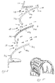
- a fender is shown generally at 10 and comprises a leading section 12 having a leading edge 14, a top section 11 and a trailing section 16 having a trailing edge 18.
- the fender also includes a side edge 20 terminating in a U-shaped recess and mounting brackets 22a and 22b which are welded or otherwise secured to the fender 10.
- the mounting brackets are bolted to the chassis in any suitable manner.
- the leading section 12 is characterized by an opening 24 in which is received an air scoop 26.
- the air scoop 26 comprises a substantially rectangular frame 28 having a lip 30 extending outwardly therefrom. Secured in the frame are three horizontal blades spaced in parallel, spaced apart relationship 32a, 32b and 32c respectively. These blades define openings 34a, 34b and 34c, see Fig. 2.
- the air scoop 26 is secured to the fender 10 by bolting (or otherwise fixing) the lip 30 of the frame to the leading section 12 of the fender.
- the blades 32a, 32b and 32c of the air scoop 26 are shown more clearly.
- the blades are parabolic-shaped and comprise outer surfaces 36a, 36b and 36c and inner surfaces 40a, 40b and 40c.
- the blade openings 34a, 34b and 34c are non-uniform.
- the opening 34a is smaller than the openings 34b and 34c.
- the openings are approximately 25, 32 and 38 mm(1" 1 1/4", 1 1/2") respectively.
- the widths of the blades range from 35.5 to 46 cm (14" to 18").
- the shape of the blades shown in Fig. 3 correspond to a working example. This spacing ensures a greater air flow in the upper quadrant of the rotating tire.
- the air flowing over and through the opposed curved surfaces i.e. through the openings, has an increased velocity compared to flowing over and through flat surfaces.
- the spray is shown in block arrows and the air flow is shown in linear arrows.
- This configuration in combination with the top fender or underside of a carriage and a side shield (to be described) pulls a partial vacuum within the fender (leading section, top and side shield) and results in the air carrying moisture exiting the fender at the rear of the fender.
- a side shield 42 is shown and comprises a wall 44 and an upper edge 46 which terminates in an offset lip 48.
- the side shield 42 includes a bottom edge 50.
- the offset lip 48 is adapted to be received in the U-shaped recess of the edge 20.
- the lip 48 is out away at its leading edge at 52.
- An upstream louver 54 extends outwardly from the side wall 44 and the louver 54 includes a leading edge 56, and a side wall 58 which define a slot-like aperture 60.
- an intermediate louver 62 extends outwardly from the side wall 44 and includes a leading edge 64 and a side wall 66 which define a slot-like aperture 68.
- a downstream louver 70 extends outwardly from the side wall 44 and includes a leading edge 72, a side wall 74 which define a slot-like aperture 78.
- the aperture 68 is greater than aperture 60 and the aperture 78 is greater than the aperture 68.
- the side louvers are spaced so as to direct the incoming air into the wheel rim and onto the brake drums behind the rim.
- a spring loaded rod 80 together with an associated spring 82 is secured to the inside surface inner edge 20 of the front fender 10.
- a strap 84 Secured to the inside of the side shield 42 is a strap 84.
- the end of the spring loaded rod 80 is journaled to the side shield 42 at 86.
- the side shield 42 is secured in place by the lip 48 being received in the edge 20 and being locked in place by a cylinder lock 88.
- the lock 88 is released, the side shield rotated downwardly and then moved slightly outwardly from the fender.
- the spring 82 allows for this flexibility.
- the side shield is then rotated upwardly, as shown in Fig. 5, to provide access to the tire.
- the cutaway of the lip 48 at 52 allows for the necessary clearance.
- the air flows through the air scoop 26 and into the control zone, contacting the rotating tire.
- the spray is controlled and directed to the trailing section of the fender.
- the spray is not cast back through the scoop from the rotating tire.
- the air also flows through the apertures 60, 68 and 78 in the side shield 42 and is discharged onto the rotating tire and onto the brake assembly.
- the apertures are sized in a ratio of approximately 25:32:38mm (1", 1 1/4", 1 1/2") front to back to ensure uniform flow of air into the control zone and onto the rotating tire and the brake assembly.
- various ratios among the apertures will be well within the skill of the art.
- the speed at which the air exits the fender at the trailing edge 18 is about 170 km/h (154 feet per second).
- the centrifugal force of the spray being cast from the rotating wheel actually caused the spray to pass through the openings in the leading portion of the fender. Therefore, as shown in Fig. 3, when the air stream strikes the nose of the fender, the air is directed across the concave surface and into the quadrant and across the lower surface.
- the flow of the air through the openings for the blades 32a, 32b and 32c prevents the spray from flowing through the opening which was not the case when flat blades per se were used. Further, the concave surface collects the forwardly cast spray from the rotating tire which collected spray (water) is ultimately carried rearwardly and discharged at the rear of the fender.
- the air which is deflected downwardly helps to "lock in” the residual water still adhering to the face of the rotating tire and the underside hook traps the water that is being thrown from the spinning tire.
- the front fender 10 is used in combination with a back fender 10' in a double axle arrangement.
- a top blade 102 extends under and is spaced apart from the top section 104 of the fender and defines therewith an air scoop opening 106.
- the top blade 102 and the top section 104 define a flow path of diminishing cross-sectional area such that air flowing through the scoop is compressed.
- the direction of discharge is such that the adiabatically expanded cooled air is directed onto and between the rotating tires to assist in cooling of the tires and the brakes of the tires.
- the blades of the air scoop 26 have been shown in a uniform, parallel, spaced apart relationship.
- the number of blades can vary and the spacing between the blades can be equal (Fig. 8) or non-uniform (Fig. 3).
- the blades can be adjustable such as by pinning them to the side walls or by positioning them and then bolting them in place.
- the blades can also be non-parallel with reference to the axis of the rotating wheel (Fig. 9).
- slot-like apertures have been shown in spaced apart, parallel relationship and are dimensioned to proportion the flow of air into the control zone to cool the tire and brake assembly. These slots may assume other geometric configurations as long as the air flow is uniformly distributed into the control zone.
- the wheels themselves may be recessed within a well such as with vans or buses. In this situation, it would not only be impractical but would serve no purpose to attempt to insert the whole fender design within the well.
- the side wall per se could be used and attached to the well in a manner that 'skirts' where once secured to cover the rear tires of automobiles for aesthetic purposes.
Description
Claims (9)
- A fender (10) which comprises a generally planar leading section (12) spaced apart from and extending generally across the leading upper quadrant of a tyre; a plurality of blades (32a, 32b, 32c) formed in the leading section, and spaced apart to define flow passages (34b, 34c) therebetween, the blades comprising outer surfaces (36a, 36b, 36c) and concave inner surfaces (40a, 40b, 40c) spaced apart from the rotating tyre, each blade having a lower part and an upper part,
characterised in thatsuch that spray, cast forwardly from the rotating tyre in the region adjacent the leading section is both directed back toward the tyre and downwardly and collected by the inner surfaces and subsequently discharged.the outer surfaces (36a, 36b, 36c) have a parabolic shape, defining therebetween flow paths (34b, 34c) of diminishing cross section,the lower parts of the blades are directed downwards and backwards towards the tyre, andthe upper part of the blades are directed upwards and backwards towards the tyre, - A fender according to claim 1 wherein the blades (32a, 32b, 32c) are spaced apart in uniform parallel relationship.
- A fender according to claim 1 wherein the blades (32a, 32b, 32c) are spaced apart in parallel non-uniform relationship.
- A fender according to claim 1 wherein the blades (32a, 32b, 32c) are spaced apart in non-parallel non-uniform relationship.
- A fender according to claim 3 or claim 4 wherein the flow paths (34b, 34c) increase in size from the upper to the lower portion of the leading section (12).
- A fender according to any preceding claim which comprises a top section (11) which cooperates with the leading section (12) and is spaced apart from and extends across the top portion of the tyre, and wherein the top blade (32a) extends under and is spaced apart from the top section and defines therewith an air scoop (26), the air scoop comprising a flow passage (34a) of diminishing cross sectional area which results in the adiabatic discharge of the air flowing through the air scoop onto the rotating tyre and associated brake assembly.
- A fender according to any preceding claim which comprises a trailing portion (16) spaced apart from and extending generally across the trailing upper quadrant of the tyre, whereby at least a portion of the water is discharged downwardly from the trailing portion.
- A fender according to any preceding claim which comprises first and second fenders (10, 10') arrayed in tandem relationship for a dual axle vehicle.
- A fender according to any preceding claim in combination with a side shield (42) comprising:means (48) to maintain the shield in spaced apart relationship from the rotating tyre, the shield lying in a plane substantially perpendicular to the axis of the rotating tyre; anda plurality of louvres (54, 62, 70) formed in the shield, comprising at least a leading louvre (54) and a trailing louvre (70), the louvres being non-uniformly proportioned such that the rate of the air discharged from the louvres is substantially equal to ensure uniform distribution of air flowing into the tyre and associated brake assembly.
Priority Applications (1)
| Application Number | Priority Date | Filing Date | Title |
|---|---|---|---|
| AT95907113T ATE181296T1 (en) | 1995-01-18 | 1995-01-18 | FENDER FOR COOLING TIRES AND BRAKES AND FOR WATER SPRAY CONTROL |
Applications Claiming Priority (1)
| Application Number | Priority Date | Filing Date | Title |
|---|---|---|---|
| PCT/IB1995/000071 WO1996022215A1 (en) | 1995-01-18 | 1995-01-18 | Fender for cooling tires and brakes and to control spray |
Publications (2)
| Publication Number | Publication Date |
|---|---|
| EP0757642A1 EP0757642A1 (en) | 1997-02-12 |
| EP0757642B1 true EP0757642B1 (en) | 1999-06-16 |
Family
ID=11004318
Family Applications (1)
| Application Number | Title | Priority Date | Filing Date |
|---|---|---|---|
| EP95907113A Expired - Lifetime EP0757642B1 (en) | 1995-01-18 | 1995-01-18 | Fender for cooling tires and brakes and to control spray |
Country Status (4)
| Country | Link |
|---|---|
| EP (1) | EP0757642B1 (en) |
| AU (1) | AU704671B2 (en) |
| DE (1) | DE69510345T2 (en) |
| WO (1) | WO1996022215A1 (en) |
Cited By (1)
| Publication number | Priority date | Publication date | Assignee | Title |
|---|---|---|---|---|
| EP3040256A1 (en) | 2014-12-30 | 2016-07-06 | Skoda Auto a.s. | Wheel well of a motor vehicle |
Families Citing this family (5)
| Publication number | Priority date | Publication date | Assignee | Title |
|---|---|---|---|---|
| FR2828863B1 (en) * | 2001-08-21 | 2004-03-12 | Michel Cibois | PROTECTION AGAINST SPOTS FROM VEHICLE WHEELS |
| DE102006002289A1 (en) * | 2006-01-18 | 2007-07-26 | Daimlerchrysler Ag | Mudguard for covering vehicle wheel, has recess which is covered with separate mudguard part within mudguard and is limited rotating from mudguard |
| DE202011051494U1 (en) * | 2011-09-30 | 2013-01-10 | Al-Ko Kober Ag | Mudguard with insert element |
| DE102018210804B8 (en) | 2018-06-29 | 2020-03-05 | Audi Ag | Body for a motor vehicle |
| JP7026670B2 (en) * | 2019-12-25 | 2022-02-28 | しげる工業株式会社 | Vehicle mudguard |
Family Cites Families (5)
| Publication number | Priority date | Publication date | Assignee | Title |
|---|---|---|---|---|
| CH175839A (en) * | 1934-05-17 | 1935-03-15 | Verkehrspatente Ag F | Ventilation device for the wheel tires of vehicles, in particular automobiles. |
| US4436319A (en) * | 1981-10-07 | 1984-03-13 | Clutter James E | Vehicle wheel splash guard |
| US5100177A (en) * | 1987-07-23 | 1992-03-31 | Becker John H | Tire spray control device |
| US4858941A (en) * | 1987-07-23 | 1989-08-22 | Becker John H | Tire spray control device |
| DK434888D0 (en) * | 1988-08-04 | 1988-08-04 | Pedersen Johannes | VEHICLES WITH PNEUMATIC TIRES AND MEASURES TO REDUCE TIRES |
-
1995
- 1995-01-18 DE DE69510345T patent/DE69510345T2/en not_active Expired - Fee Related
- 1995-01-18 EP EP95907113A patent/EP0757642B1/en not_active Expired - Lifetime
- 1995-01-18 WO PCT/IB1995/000071 patent/WO1996022215A1/en active IP Right Grant
- 1995-01-18 AU AU15444/95A patent/AU704671B2/en not_active Ceased
Cited By (1)
| Publication number | Priority date | Publication date | Assignee | Title |
|---|---|---|---|---|
| EP3040256A1 (en) | 2014-12-30 | 2016-07-06 | Skoda Auto a.s. | Wheel well of a motor vehicle |
Also Published As
| Publication number | Publication date |
|---|---|
| DE69510345D1 (en) | 1999-07-22 |
| AU704671B2 (en) | 1999-04-29 |
| EP0757642A1 (en) | 1997-02-12 |
| DE69510345T2 (en) | 2000-02-17 |
| WO1996022215A1 (en) | 1996-07-25 |
| AU1544495A (en) | 1996-08-07 |
Similar Documents
| Publication | Publication Date | Title |
|---|---|---|
| US5460411A (en) | Fender for cooling tires and brakes and to control spray | |
| US10829168B2 (en) | Aerodynamic trucking systems | |
| US5564750A (en) | Energy saving and heat venting vehicle mud flap | |
| US5375882A (en) | Mist suppressant panels for a vehicle and a method of suppressing mist | |
| US6786512B2 (en) | Vehicle wheel shield for air control | |
| CA2999993C (en) | Aerodynamic trucking systems | |
| CA1217521A (en) | Spray shield for automotive vehicles | |
| CA2570668C (en) | Grille arrangement for a drive unit enclosure | |
| US6260911B1 (en) | Air duct for cooling rotating tires | |
| US6367841B1 (en) | Mudguard assembly | |
| US11772718B2 (en) | Aerodynamic trucking systems | |
| EP0757642B1 (en) | Fender for cooling tires and brakes and to control spray | |
| US4858941A (en) | Tire spray control device | |
| US5100177A (en) | Tire spray control device | |
| US20020056985A1 (en) | Truck spray control system | |
| CA2185934A1 (en) | Fender for cooling tires and brakes and to control spray | |
| JP6913739B2 (en) | Vehicles with enhanced traction and equipment on vehicles | |
| CA3050236C (en) | Aerodynamic system with dual zone fairing for truck | |
| US20040066028A1 (en) | Splashguard | |
| CA3138463A1 (en) | Aerodynamic trucking systems | |
| JPH04283126A (en) | Exhaust structure of industrial vehicle | |
| CA2023532A1 (en) | Tire spray control device | |
| WO2004078561A1 (en) | Means for redirecting tyre spray | |
| JPS619331A (en) | Air venting device in racing car |
Legal Events
| Date | Code | Title | Description |
|---|---|---|---|
| PUAI | Public reference made under article 153(3) epc to a published international application that has entered the european phase |
Free format text: ORIGINAL CODE: 0009012 |
|
| 17P | Request for examination filed |
Effective date: 19961202 |
|
| AK | Designated contracting states |
Kind code of ref document: A1 Designated state(s): AT BE CH DE DK ES FR GB GR IE IT LI LU MC NL PT SE |
|
| AX | Request for extension of the european patent |
Free format text: LT PAYMENT 961202;SI PAYMENT 961202 |
|
| R17P | Request for examination filed (corrected) |
Effective date: 19961017 |
|
| RAX | Requested extension states of the european patent have changed |
Free format text: LT PAYMENT 961017;SI PAYMENT 961017 |
|
| 17Q | First examination report despatched |
Effective date: 19971017 |
|
| GRAG | Despatch of communication of intention to grant |
Free format text: ORIGINAL CODE: EPIDOS AGRA |
|
| GRAG | Despatch of communication of intention to grant |
Free format text: ORIGINAL CODE: EPIDOS AGRA |
|
| GRAG | Despatch of communication of intention to grant |
Free format text: ORIGINAL CODE: EPIDOS AGRA |
|
| GRAH | Despatch of communication of intention to grant a patent |
Free format text: ORIGINAL CODE: EPIDOS IGRA |
|
| GRAH | Despatch of communication of intention to grant a patent |
Free format text: ORIGINAL CODE: EPIDOS IGRA |
|
| GRAA | (expected) grant |
Free format text: ORIGINAL CODE: 0009210 |
|
| AK | Designated contracting states |
Kind code of ref document: B1 Designated state(s): AT BE CH DE DK ES FR GB GR IE IT LI LU MC NL PT SE |
|
| AX | Request for extension of the european patent |
Free format text: LT PAYMENT 19961017;SI PAYMENT 19961017 |
|
| LTIE | Lt: invalidation of european patent or patent extension | ||
| PG25 | Lapsed in a contracting state [announced via postgrant information from national office to epo] |
Ref country code: NL Free format text: LAPSE BECAUSE OF FAILURE TO SUBMIT A TRANSLATION OF THE DESCRIPTION OR TO PAY THE FEE WITHIN THE PRESCRIBED TIME-LIMIT Effective date: 19990616 Ref country code: LI Free format text: LAPSE BECAUSE OF FAILURE TO SUBMIT A TRANSLATION OF THE DESCRIPTION OR TO PAY THE FEE WITHIN THE PRESCRIBED TIME-LIMIT Effective date: 19990616 Ref country code: GR Free format text: LAPSE BECAUSE OF NON-PAYMENT OF DUE FEES Effective date: 19990616 Ref country code: ES Free format text: THE PATENT HAS BEEN ANNULLED BY A DECISION OF A NATIONAL AUTHORITY Effective date: 19990616 Ref country code: CH Free format text: LAPSE BECAUSE OF FAILURE TO SUBMIT A TRANSLATION OF THE DESCRIPTION OR TO PAY THE FEE WITHIN THE PRESCRIBED TIME-LIMIT Effective date: 19990616 Ref country code: BE Free format text: LAPSE BECAUSE OF FAILURE TO SUBMIT A TRANSLATION OF THE DESCRIPTION OR TO PAY THE FEE WITHIN THE PRESCRIBED TIME-LIMIT Effective date: 19990616 Ref country code: AT Free format text: LAPSE BECAUSE OF FAILURE TO SUBMIT A TRANSLATION OF THE DESCRIPTION OR TO PAY THE FEE WITHIN THE PRESCRIBED TIME-LIMIT Effective date: 19990616 |
|
| REF | Corresponds to: |
Ref document number: 181296 Country of ref document: AT Date of ref document: 19990715 Kind code of ref document: T |
|
| REG | Reference to a national code |
Ref country code: CH Ref legal event code: EP |
|
| REF | Corresponds to: |
Ref document number: 69510345 Country of ref document: DE Date of ref document: 19990722 |
|
| RAP2 | Party data changed (patent owner data changed or rights of a patent transferred) |
Owner name: BECKER, JOHN H. |
|
| RIN2 | Information on inventor provided after grant (corrected) |
Free format text: BECKER, JOHN H. |
|
| REG | Reference to a national code |
Ref country code: IE Ref legal event code: FG4D |
|
| ITF | It: translation for a ep patent filed |
Owner name: LUNATI & MAZZONI S.A.S. |
|
| PG25 | Lapsed in a contracting state [announced via postgrant information from national office to epo] |
Ref country code: PT Free format text: LAPSE BECAUSE OF FAILURE TO SUBMIT A TRANSLATION OF THE DESCRIPTION OR TO PAY THE FEE WITHIN THE PRESCRIBED TIME-LIMIT Effective date: 19990916 Ref country code: DK Free format text: LAPSE BECAUSE OF FAILURE TO SUBMIT A TRANSLATION OF THE DESCRIPTION OR TO PAY THE FEE WITHIN THE PRESCRIBED TIME-LIMIT Effective date: 19990916 |
|
| ET | Fr: translation filed | ||
| NLV1 | Nl: lapsed or annulled due to failure to fulfill the requirements of art. 29p and 29m of the patents act | ||
| REG | Reference to a national code |
Ref country code: CH Ref legal event code: PL |
|
| PG25 | Lapsed in a contracting state [announced via postgrant information from national office to epo] |
Ref country code: LU Free format text: LAPSE BECAUSE OF NON-PAYMENT OF DUE FEES Effective date: 20000118 Ref country code: IE Free format text: LAPSE BECAUSE OF NON-PAYMENT OF DUE FEES Effective date: 20000118 |
|
| PG25 | Lapsed in a contracting state [announced via postgrant information from national office to epo] |
Ref country code: MC Free format text: THE PATENT HAS BEEN ANNULLED BY A DECISION OF A NATIONAL AUTHORITY Effective date: 20000131 |
|
| PLBE | No opposition filed within time limit |
Free format text: ORIGINAL CODE: 0009261 |
|
| STAA | Information on the status of an ep patent application or granted ep patent |
Free format text: STATUS: NO OPPOSITION FILED WITHIN TIME LIMIT |
|
| 26N | No opposition filed | ||
| REG | Reference to a national code |
Ref country code: IE Ref legal event code: MM4A |
|
| PGFP | Annual fee paid to national office [announced via postgrant information from national office to epo] |
Ref country code: FR Payment date: 20010122 Year of fee payment: 7 |
|
| PGFP | Annual fee paid to national office [announced via postgrant information from national office to epo] |
Ref country code: SE Payment date: 20010124 Year of fee payment: 7 |
|
| PGFP | Annual fee paid to national office [announced via postgrant information from national office to epo] |
Ref country code: DE Payment date: 20010126 Year of fee payment: 7 |
|
| PGFP | Annual fee paid to national office [announced via postgrant information from national office to epo] |
Ref country code: GB Payment date: 20010130 Year of fee payment: 7 |
|
| REG | Reference to a national code |
Ref country code: GB Ref legal event code: IF02 |
|
| PG25 | Lapsed in a contracting state [announced via postgrant information from national office to epo] |
Ref country code: GB Free format text: LAPSE BECAUSE OF NON-PAYMENT OF DUE FEES Effective date: 20020118 |
|
| PG25 | Lapsed in a contracting state [announced via postgrant information from national office to epo] |
Ref country code: SE Free format text: LAPSE BECAUSE OF NON-PAYMENT OF DUE FEES Effective date: 20020119 |
|
| PG25 | Lapsed in a contracting state [announced via postgrant information from national office to epo] |
Ref country code: DE Free format text: LAPSE BECAUSE OF NON-PAYMENT OF DUE FEES Effective date: 20020801 |
|
| EUG | Se: european patent has lapsed |
Ref document number: 95907113.5 |
|
| GBPC | Gb: european patent ceased through non-payment of renewal fee |
Effective date: 20020118 |
|
| PG25 | Lapsed in a contracting state [announced via postgrant information from national office to epo] |
Ref country code: FR Free format text: LAPSE BECAUSE OF NON-PAYMENT OF DUE FEES Effective date: 20020930 |
|
| REG | Reference to a national code |
Ref country code: FR Ref legal event code: ST |
|
| PG25 | Lapsed in a contracting state [announced via postgrant information from national office to epo] |
Ref country code: IT Free format text: LAPSE BECAUSE OF NON-PAYMENT OF DUE FEES Effective date: 20050118 |