EP0757617B1 - A method and a device for making concrete products - Google Patents
A method and a device for making concrete products Download PDFInfo
- Publication number
- EP0757617B1 EP0757617B1 EP95915917A EP95915917A EP0757617B1 EP 0757617 B1 EP0757617 B1 EP 0757617B1 EP 95915917 A EP95915917 A EP 95915917A EP 95915917 A EP95915917 A EP 95915917A EP 0757617 B1 EP0757617 B1 EP 0757617B1
- Authority
- EP
- European Patent Office
- Prior art keywords
- motion
- path
- feeding hopper
- hopper
- mould
- Prior art date
- Legal status (The legal status is an assumption and is not a legal conclusion. Google has not performed a legal analysis and makes no representation as to the accuracy of the status listed.)
- Expired - Lifetime
Links
- 239000004567 concrete Substances 0.000 title claims abstract description 35
- 238000000034 method Methods 0.000 title claims abstract description 11
- 230000033001 locomotion Effects 0.000 claims abstract description 45
- 238000005266 casting Methods 0.000 claims abstract description 31
- 239000000203 mixture Substances 0.000 claims description 7
- 230000007423 decrease Effects 0.000 claims description 2
- 239000000047 product Substances 0.000 description 10
- 239000004568 cement Substances 0.000 description 3
- XLYOFNOQVPJJNP-UHFFFAOYSA-N water Substances O XLYOFNOQVPJJNP-UHFFFAOYSA-N 0.000 description 3
- 230000000694 effects Effects 0.000 description 2
- 239000012467 final product Substances 0.000 description 2
- 230000002787 reinforcement Effects 0.000 description 2
- 239000007787 solid Substances 0.000 description 2
- 230000003247 decreasing effect Effects 0.000 description 1
- 230000002349 favourable effect Effects 0.000 description 1
- 230000001737 promoting effect Effects 0.000 description 1
- 239000011150 reinforced concrete Substances 0.000 description 1
- 238000007493 shaping process Methods 0.000 description 1
- 238000009751 slip forming Methods 0.000 description 1
- 230000003068 static effect Effects 0.000 description 1
Images
Classifications
-
- B—PERFORMING OPERATIONS; TRANSPORTING
- B28—WORKING CEMENT, CLAY, OR STONE
- B28B—SHAPING CLAY OR OTHER CERAMIC COMPOSITIONS; SHAPING SLAG; SHAPING MIXTURES CONTAINING CEMENTITIOUS MATERIAL, e.g. PLASTER
- B28B1/00—Producing shaped prefabricated articles from the material
- B28B1/08—Producing shaped prefabricated articles from the material by vibrating or jolting
- B28B1/084—Producing shaped prefabricated articles from the material by vibrating or jolting the vibrating moulds or cores being moved horizontally for making strands of moulded articles
-
- B—PERFORMING OPERATIONS; TRANSPORTING
- B28—WORKING CEMENT, CLAY, OR STONE
- B28B—SHAPING CLAY OR OTHER CERAMIC COMPOSITIONS; SHAPING SLAG; SHAPING MIXTURES CONTAINING CEMENTITIOUS MATERIAL, e.g. PLASTER
- B28B13/00—Feeding the unshaped material to moulds or apparatus for producing shaped articles; Discharging shaped articles from such moulds or apparatus
- B28B13/02—Feeding the unshaped material to moulds or apparatus for producing shaped articles
Definitions
- This invention relates to a method of casting concrete products with a slide casting apparatus moving along a base so that concrete mix is fed into a mould through a feeding hopper fitted above the mould and tapering downward towards the discharge opening and being moved along a path of motion deviating from the path of travel of the apparatus.
- the invention also relates to a slide casting apparatus for casting concrete products and comprising a mould moving in relation to a base and formed by side walls and a top plate and a feeding hopper fitted above the mould and tapering downward towards the discharge opening for feeding concrete mix into the mould, whereby the feeding hopper is provided with means for moving the hopper along a path of motion deviating from the path of travel of the apparatus.
- Such apparatus are also known wherein two feeding hoppers are located one above the other and the lower one is vibrated to compact the concrete.
- Such devices are described, for example, in SU Patent Publications 455 010 and 751 629.
- a casting apparatus having a vibrating device acting on a sloping plate behind a feed hopper.
- a slipforming casting apparatus comprising a hopper and a trailing sledge with a vibrating device.
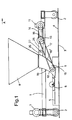
- the apparatus according to the invention has a frame 1, which moves on wheels 2 along rails 4 on a base 3.
- the frame supports a casting mould formed by side walls and a top plate 5.
- the top plate is provided with a vibrator 6.
- the driving wheels are driven by a driving mechanism 7 and the device moves in the direction shown by arrow A.
- the frame supports an upper and a lower feeding hopper 8 and 9, one on top of the other and separate from each other.
- Both hoppers taper towards their bottom end.
- a wall 10 at the trailing end of the lower hopper is tilted so that the bottom end of its inner surface slopes downward towards the trailing end of the machine.
- the bottom end of the hopper forms an extension to the mould's top plate 5.
- the leading wall 10' is also tilted in a corresponding way.
- the cross-section of the lower hopper decreases in the concrete compacting zone from the top downward by as much as 80 per cent.
- the suitable reduction in the cross-section depends on the quality of the concrete and on the need for compacting.
- the lower hopper is provided with its own driving mechanism bringing the hopper into an oscillating motion.
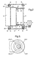
- a motor 11 through a belt 14 and a belt pulley 15 rotates a shaft 13, which is journalled in brackets 12 mounted to the frame.
- the shaft ends carry belt pulleys 16 from which the motion is transferred by way of belts 17 through belt pulleys 19 to shafts 18 journalled on the sides of the lower hopper.
- Shafts 18 are supported by bearings 20 in the frame.
- Eccentric cams 21 are located between shafts 18 and bearings 22 on the hopper sides.
- the shaft 13 is connected by eccentric cams 23 and bearings 24 to levers 25, each of which is attached through a link 27 to lugs 26 located at the top end of the lower hopper, on two sides of the hopper.
- the shaft 18 mounted eccentrically to the bottom part of the hopper 9 makes the bottom end of the hopper move under mechanical control along a forced circular path of motion in a vertical plane in the device's direction of motion.
- the motion is transferred to the top end of the lower hopper by levers 25 journalled eccentrically to shaft 13.
- the directions of rotation of the shafts 13 and 18 are counterclockwise in the drawings.
- the cams 23 and 21 on the shafts 13 and 18 are arranged so that their phase difference is preferably about 90° as the lower cam 21 moves ahead of the upper cam 23.
- the vertical components of motions transferred to the top part of the hopper from the lower cam 21 and from the upper cam 23 by way of link 27 cancel one another, while the horizontal components strengthen one another. This has the result that the path of motion of the top end is a back-and-forth longitudinal motion almost in a horizontal plane.
- the slide casting machine is moved in a conventional manner on the base driven by the driving mechanism 7.
- the concrete will not yet be compacted in the top end of the hopper.
- the horizontal vibration promotes flowing of the concrete through the top end of the hopper.
- the motion also has a vertical component which causes efficient compacting of the concrete.
- the feeding hopper forms a pressurization zone promoting a good flowing of the concrete but preventing arching in the top end of the hopper.
- the path of motion described above in combination with a decreasing cross-section causes compacting of the concrete close to its final density. Density and surface quality may be further improved by vibrating the top plate.
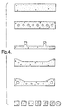
- the cross-sectional shape of a product made by the method according to the invention may vary very much. It may be either solid or it may contain hollows which are made by shaping mandrels in the device which are known as such. A rectangular solid or hollowed basic shape may also contain protrusions or recesses. Figure 4 shows different cross-sectional product shapes by way of example.
- the reinforcement of a reinforced concrete product to be made by slide casting may be prestressed or non-prestressed, so-called static reinforcement.
- the path of motion according to the invention can be achieved also in ways other than with the described cam-articulated arm structure.
- the vertical component of the motion of the top end can be limited, for example, by means of a suitable slide arrangement or other stops or guides.
- a mechanically controlled forced motion can also be achieved by controlled vibration.
- Such a controlled vibration is different, for example, from the vibration of a flexibly supported hopper in that the hopper's path of motion is not a random path, but will follow a certain predetermined path.
- the upper hopper a necessary part of the invention, it may be replaced with some other feeding arrangement to keep the oscillating hopper constantly and adequately filled so that the concrete may be compacted already in the hopper.
- a conveyor belt or a feeding screw may be used which moves the concrete from a storage container of the device into the oscillating hopper.
- the horizontal component of the hopper's path of motion is longitudinal.
- the horizontal component may also be arranged to be crosswise to the machine's direction of travel.
- the compacting effect can be further enhanced by forming the wall at the trailing end of the lower hopper separate from the rest of the hopper and by moving it separately. Its path of motion may be, for example, opposite to the motion of the rest of the hopper in the horizontal plane, whereby the compacting effect will enhance compacting of the concrete.
Landscapes
- Engineering & Computer Science (AREA)
- Manufacturing & Machinery (AREA)
- Chemical & Material Sciences (AREA)
- Ceramic Engineering (AREA)
- Mechanical Engineering (AREA)
- Devices For Post-Treatments, Processing, Supply, Discharge, And Other Processes (AREA)
- Manufacturing Of Tubular Articles Or Embedded Moulded Articles (AREA)
- On-Site Construction Work That Accompanies The Preparation And Application Of Concrete (AREA)
- Curing Cements, Concrete, And Artificial Stone (AREA)
- Press-Shaping Or Shaping Using Conveyers (AREA)
- Crystals, And After-Treatments Of Crystals (AREA)
- Underground Or Underwater Handling Of Building Materials (AREA)
Abstract
Description
Claims (11)
- A method of casting concrete products with a slide casting apparatus moving along a base (3) so that concrete mix is fed into a mould through a feeding hopper (9) fitted above the mould and tapering downward towards the discharge opening and being moved along a path of motion deviating from the path of travel of the apparatus, the feeding hopper (9) being moved along a controlled path of motion, characterized in that that the vertical component of the path of motion of the Feeding hopper's bottom part exceeds the vertical component of the path of motion of the feeding hopper's (9) top part, which > 0 or = 0.
- A method as defined in claim 1, characterized in that the feeding hopper (9) is moved so that the path of motion of its bottom part also comprises a horizontal component besides the vertical component.
- A method as defined in claim 2, characterized in that the feeding hopper (9) is moved so that the horizontal component of the path of motion of its top part exceeds the horizontal component of the path of motion of the feeding hopper's (9) bottom part.
- A method as defined in any claim 1-3, characterized in that the change in direction of the concrete flow between the movable feeding hopper (9) and a top plate (5) of the mould is no more than 90°, preferably no more than 60°.
- A slide casting apparatus for casting concrete products and comprising a mould movable in relation to a base (3) and formed by side walls and a top plate (5) and a feeding hopper (9) fitted above the mould and tapering downward towards the discharge opening for feeding concrete mix into the mould, whereby the feeding hopper (9) is provided with means (11, 13, 17, 18) for moving the hopper along a path of motion deviating from the path of travel of the rest of the apparatus, characterized in that the path of motion of the feeding hopper (9) is controlled and the vertical component of the path of motion of its bottom part exceeds the vertical component of the path of motion of the feeding hopper's (9) top part, which > 0 or = 0.
- A slide casting apparatus as defined in claim 5, characterized in that the bottom part of the movable feeding hopper (9) is connected with a cam (21) and the top part is connected through an articulated arm (25) with another cam (23), whereby the cam (23) connected to the top part is so arranged, that the vertical component of motion caused by it in the top part of the feeding hopper (9) cancels the vertical component of motion caused in the top part by the cam (21) connected to the bottom part of the feeding hopper.
- A slide casting apparatus as defined in claim 5, characterized in that it is equipped with a vibrator which vibrates the movable hopper under forced mechanical control.
- A slide casting apparatus as defined in any of claims 5-7, characterized in that the leading wall (10') and/or the trailing wall (10) of the movable feeding hopper (9) is/are tilted, the inner surface(s) of said wall(s) sloping downward towards the trailing side of the apparatus.
- A slide casting apparatus as defined in any of claims 5-8, characterized in that the bottom end of the leading wall (10') of the movable feeding hopper (9) extends below the top plate (5) of the mould.
- A slide casting apparatus as defined in any of claims 5-9, characterized in that the trailing end wall (10) of the movable feeding hopper (9) is separate from the remaining hopper and is movable along a path of motion deviating from the path of motion of the remaining hopper.
- A slide casting apparatus as defined in any of claims 5-10, characterized in that the cross-section of the movable feeding hopper (9) decreases from the top downward in the concrete compacting zone formed by the bottom end of the hopper by as much as 80 per cent.
Applications Claiming Priority (3)
| Application Number | Priority Date | Filing Date | Title |
|---|---|---|---|
| FI941992 | 1994-04-29 | ||
| FI941992A FI102057B1 (en) | 1994-04-29 | 1994-04-29 | Method and apparatus for casting concrete products |
| PCT/FI1995/000228 WO1995029799A1 (en) | 1994-04-29 | 1995-04-26 | A method and a device for making concrete products |
Publications (2)
| Publication Number | Publication Date |
|---|---|
| EP0757617A1 EP0757617A1 (en) | 1997-02-12 |
| EP0757617B1 true EP0757617B1 (en) | 2001-11-21 |
Family
ID=8540618
Family Applications (1)
| Application Number | Title | Priority Date | Filing Date |
|---|---|---|---|
| EP95915917A Expired - Lifetime EP0757617B1 (en) | 1994-04-29 | 1995-04-26 | A method and a device for making concrete products |
Country Status (13)
| Country | Link |
|---|---|
| US (1) | US5779953A (en) |
| EP (1) | EP0757617B1 (en) |
| JP (1) | JP3619967B2 (en) |
| KR (1) | KR100359197B1 (en) |
| AT (1) | ATE209087T1 (en) |
| AU (1) | AU2261195A (en) |
| DE (1) | DE69524078T2 (en) |
| DK (1) | DK0757617T3 (en) |
| ES (1) | ES2168362T3 (en) |
| FI (1) | FI102057B1 (en) |
| NO (1) | NO302650B1 (en) |
| PT (1) | PT757617E (en) |
| WO (1) | WO1995029799A1 (en) |
Families Citing this family (7)
| Publication number | Priority date | Publication date | Assignee | Title |
|---|---|---|---|---|
| FI3057U1 (en) * | 1996-12-30 | 1997-09-18 | Partek Concrete Dev Oy Ab | Noise protection and noise protection panel |
| FI113850B (en) | 2002-01-30 | 2004-06-30 | Consolis Technology Oy Ab | Method and apparatus for casting concrete products |
| FI20051027L (en) * | 2005-10-12 | 2007-04-13 | Elematic Oy Ab | Method and apparatus for casting concrete mass |
| FI124185B (en) * | 2012-11-29 | 2014-04-15 | Elematic Oy Ab | Method and apparatus for casting concrete products |
| CN109483712B (en) * | 2018-12-19 | 2024-05-17 | 中交第一航务工程局有限公司 | Small-size concrete piece processing equipment |
| FI129460B (en) * | 2019-02-12 | 2022-02-28 | Elematic Oyj | Process for the production of prefabricated concrete products |
| CN111974311A (en) * | 2019-05-22 | 2020-11-24 | 南京康德祥医药科技有限公司 | Device for producing receptor regulator |
Family Cites Families (9)
| Publication number | Priority date | Publication date | Assignee | Title |
|---|---|---|---|---|
| DE1252569B (en) * | ||||
| DE965687C (en) * | 1953-03-01 | 1957-06-13 | Eisenwerke Muelheim Meiderich | Extrusion press for non-homogeneous, grainy mass mixtures of different properties and sizes of parts, especially for concrete |
| SE309556B (en) * | 1965-02-05 | 1969-03-24 | P Jonell | |
| SU507447A2 (en) * | 1971-03-04 | 1976-03-25 | Специальное Конструкторское Бюро "Кассетдеталь" | Paver |
| SU613896A1 (en) * | 1976-09-09 | 1978-07-05 | Всесоюзное Научно-Производственное Объединение "Союзжелезобетон" | Method of moulding articles from concrete mixes |
| SU688340A1 (en) * | 1976-11-09 | 1979-09-30 | А. И. Семенов | Concrete-laying machine |
| SU979124A1 (en) * | 1981-07-20 | 1982-12-07 | Ярославский политехнический институт | Apparatus for compacting concrete mixes |
| SU1097501A1 (en) * | 1983-03-16 | 1984-06-15 | Всесоюзный Государственный Проектный Институт По Строительному Машиностроению Для Сборного Железобетона "Гипростроммаш" | Concrete-placing machine |
| DE3502861A1 (en) * | 1985-01-29 | 1986-07-31 | Weckenmann Maschinen- und Stahlbau GmbH & Co KG, 7461 Dormettingen | Process and device for concrete metering in the production of concrete precast elements |
-
1994
- 1994-04-29 FI FI941992A patent/FI102057B1/en not_active IP Right Cessation
-
1995
- 1995-04-26 EP EP95915917A patent/EP0757617B1/en not_active Expired - Lifetime
- 1995-04-26 KR KR1019960705970A patent/KR100359197B1/en not_active Expired - Fee Related
- 1995-04-26 US US08/732,470 patent/US5779953A/en not_active Expired - Fee Related
- 1995-04-26 ES ES95915917T patent/ES2168362T3/en not_active Expired - Lifetime
- 1995-04-26 WO PCT/FI1995/000228 patent/WO1995029799A1/en not_active Ceased
- 1995-04-26 AT AT95915917T patent/ATE209087T1/en not_active IP Right Cessation
- 1995-04-26 PT PT95915917T patent/PT757617E/en unknown
- 1995-04-26 DK DK95915917T patent/DK0757617T3/en active
- 1995-04-26 AU AU22611/95A patent/AU2261195A/en not_active Abandoned
- 1995-04-26 JP JP52801995A patent/JP3619967B2/en not_active Expired - Fee Related
- 1995-04-26 DE DE69524078T patent/DE69524078T2/en not_active Expired - Fee Related
-
1996
- 1996-10-10 NO NO964315A patent/NO302650B1/en not_active IP Right Cessation
Also Published As
| Publication number | Publication date |
|---|---|
| FI941992A0 (en) | 1994-04-29 |
| FI941992L (en) | 1995-10-30 |
| DK0757617T3 (en) | 2002-05-13 |
| JP3619967B2 (en) | 2005-02-16 |
| NO964315D0 (en) | 1996-10-10 |
| ES2168362T3 (en) | 2002-06-16 |
| DE69524078T2 (en) | 2002-07-04 |
| PT757617E (en) | 2002-04-29 |
| NO964315L (en) | 1996-10-10 |
| ATE209087T1 (en) | 2001-12-15 |
| FI102057B (en) | 1998-10-15 |
| DE69524078D1 (en) | 2002-01-03 |
| WO1995029799A1 (en) | 1995-11-09 |
| FI102057B1 (en) | 1998-10-15 |
| KR100359197B1 (en) | 2003-02-19 |
| AU2261195A (en) | 1995-11-29 |
| JPH09512499A (en) | 1997-12-16 |
| US5779953A (en) | 1998-07-14 |
| EP0757617A1 (en) | 1997-02-12 |
| NO302650B1 (en) | 1998-04-06 |
Similar Documents
| Publication | Publication Date | Title |
|---|---|---|
| RU2554973C1 (en) | Swinging fire grate of stone processing machine loading truck | |
| CN111283845B (en) | Equipment is evenly pour to intermittent type formula filler of prefabricated concrete component processing of prefabricated building | |
| CN201300479Y (en) | Filling device for filling a mold with a pourable molding material | |
| KR0161275B1 (en) | Method and apparatus for forming concrete blocks | |
| US5779953A (en) | Method and a device for making concrete products | |
| US6991092B2 (en) | Belt conveyor for transporting tobacco materials | |
| CN1048209C (en) | Method and apparatus for producing a contrete product | |
| US1694563A (en) | Method of molding ceramic materials | |
| SU1621807A3 (en) | Device for condinuous moulding of articles from low-plasticity concrete mixes | |
| US2382458A (en) | Apparatus and method for molding concrete blocks | |
| US4978011A (en) | Sorting machine for grained products | |
| US5123831A (en) | Concrete extrusion machine | |
| US4090827A (en) | Apparatus for moulding and extrusion | |
| HU192118B (en) | Method for continuous moulding objects made of material of high viscosity and mould for slide moulding | |
| FI74649B (en) | FARING EQUIPMENT FOR THE PRODUCTION OF CONCRETE PRODUCTS. | |
| US4432717A (en) | Apparatus for filling molds carried on a conveyor belt | |
| RU2175699C1 (en) | Device for molding items from loose dispersible materials | |
| US3520348A (en) | Fill carriages for automatic matchplate moulding machines | |
| US2963762A (en) | Aggregate feed and stripper apparatus for concrete block machines | |
| SU1148788A1 (en) | Installation for compacting articles of concrete mixes | |
| SU1384392A1 (en) | Installation for concrete placer | |
| SU977181A1 (en) | Concrete placer | |
| SU889436A1 (en) | Apparatus for forming flat articles from rigid concrete mix | |
| SU727452A1 (en) | Apparatus for moulding ferroconcrete articles | |
| SU1118529A1 (en) | Arrangement for shaping concrete mixture articles in form |
Legal Events
| Date | Code | Title | Description |
|---|---|---|---|
| PUAI | Public reference made under article 153(3) epc to a published international application that has entered the european phase |
Free format text: ORIGINAL CODE: 0009012 |
|
| 17P | Request for examination filed |
Effective date: 19960916 |
|
| AK | Designated contracting states |
Kind code of ref document: A1 Designated state(s): AT BE DE DK ES FR GB IE IT LU NL PT SE |
|
| RAP1 | Party data changed (applicant data changed or rights of an application transferred) |
Owner name: PARTEK CONCRETE ENGINEERING OY |
|
| 17Q | First examination report despatched |
Effective date: 20000530 |
|
| GRAG | Despatch of communication of intention to grant |
Free format text: ORIGINAL CODE: EPIDOS AGRA |
|
| GRAG | Despatch of communication of intention to grant |
Free format text: ORIGINAL CODE: EPIDOS AGRA |
|
| GRAH | Despatch of communication of intention to grant a patent |
Free format text: ORIGINAL CODE: EPIDOS IGRA |
|
| RAP1 | Party data changed (applicant data changed or rights of an application transferred) |
Owner name: PARTEK CONCRETE ENGINEERING OY |
|
| GRAH | Despatch of communication of intention to grant a patent |
Free format text: ORIGINAL CODE: EPIDOS IGRA |
|
| RAP1 | Party data changed (applicant data changed or rights of an application transferred) |
Owner name: ADDTEK RESEARCH & DEVELOPMENT OY AB |
|
| GRAA | (expected) grant |
Free format text: ORIGINAL CODE: 0009210 |
|
| AK | Designated contracting states |
Kind code of ref document: B1 Designated state(s): AT BE DE DK ES FR GB IE IT LU NL PT SE |
|
| REF | Corresponds to: |
Ref document number: 209087 Country of ref document: AT Date of ref document: 20011215 Kind code of ref document: T |
|
| REG | Reference to a national code |
Ref country code: IE Ref legal event code: FG4D |
|
| REG | Reference to a national code |
Ref country code: GB Ref legal event code: IF02 |
|
| REF | Corresponds to: |
Ref document number: 69524078 Country of ref document: DE Date of ref document: 20020103 |
|
| PG25 | Lapsed in a contracting state [announced via postgrant information from national office to epo] |
Ref country code: LU Free format text: LAPSE BECAUSE OF NON-PAYMENT OF DUE FEES Effective date: 20020426 |
|
| REG | Reference to a national code |
Ref country code: PT Ref legal event code: SC4A Free format text: AVAILABILITY OF NATIONAL TRANSLATION Effective date: 20020205 |
|
| ET | Fr: translation filed | ||
| REG | Reference to a national code |
Ref country code: ES Ref legal event code: FG2A Ref document number: 2168362 Country of ref document: ES Kind code of ref document: T3 |
|
| PLBE | No opposition filed within time limit |
Free format text: ORIGINAL CODE: 0009261 |
|
| STAA | Information on the status of an ep patent application or granted ep patent |
Free format text: STATUS: NO OPPOSITION FILED WITHIN TIME LIMIT |
|
| 26N | No opposition filed | ||
| PGFP | Annual fee paid to national office [announced via postgrant information from national office to epo] |
Ref country code: PT Payment date: 20070403 Year of fee payment: 13 |
|
| PGFP | Annual fee paid to national office [announced via postgrant information from national office to epo] |
Ref country code: NL Payment date: 20070413 Year of fee payment: 13 |
|
| PGFP | Annual fee paid to national office [announced via postgrant information from national office to epo] |
Ref country code: SE Payment date: 20070417 Year of fee payment: 13 |
|
| PGFP | Annual fee paid to national office [announced via postgrant information from national office to epo] |
Ref country code: ES Payment date: 20070418 Year of fee payment: 13 |
|
| PGFP | Annual fee paid to national office [announced via postgrant information from national office to epo] |
Ref country code: AT Payment date: 20070423 Year of fee payment: 13 |
|
| PGFP | Annual fee paid to national office [announced via postgrant information from national office to epo] |
Ref country code: DE Payment date: 20070424 Year of fee payment: 13 |
|
| PGFP | Annual fee paid to national office [announced via postgrant information from national office to epo] |
Ref country code: IE Payment date: 20070426 Year of fee payment: 13 |
|
| PGFP | Annual fee paid to national office [announced via postgrant information from national office to epo] |
Ref country code: DK Payment date: 20070427 Year of fee payment: 13 |
|
| PGFP | Annual fee paid to national office [announced via postgrant information from national office to epo] |
Ref country code: GB Payment date: 20070423 Year of fee payment: 13 |
|
| PGFP | Annual fee paid to national office [announced via postgrant information from national office to epo] |
Ref country code: IT Payment date: 20070616 Year of fee payment: 13 Ref country code: BE Payment date: 20070426 Year of fee payment: 13 |
|
| PGFP | Annual fee paid to national office [announced via postgrant information from national office to epo] |
Ref country code: FR Payment date: 20070330 Year of fee payment: 13 |
|
| BERE | Be: lapsed |
Owner name: *ADDTEK RESEARCH & DEVELOPMENT OY A.B. Effective date: 20080430 |
|
| REG | Reference to a national code |
Ref country code: PT Ref legal event code: MM4A Free format text: LAPSE DUE TO NON-PAYMENT OF FEES Effective date: 20081027 |
|
| REG | Reference to a national code |
Ref country code: DK Ref legal event code: EBP |
|
| EUG | Se: european patent has lapsed | ||
| GBPC | Gb: european patent ceased through non-payment of renewal fee |
Effective date: 20080426 |
|
| NLV4 | Nl: lapsed or anulled due to non-payment of the annual fee |
Effective date: 20081101 |
|
| PG25 | Lapsed in a contracting state [announced via postgrant information from national office to epo] |
Ref country code: PT Free format text: LAPSE BECAUSE OF NON-PAYMENT OF DUE FEES Effective date: 20081027 Ref country code: NL Free format text: LAPSE BECAUSE OF NON-PAYMENT OF DUE FEES Effective date: 20081101 Ref country code: DE Free format text: LAPSE BECAUSE OF NON-PAYMENT OF DUE FEES Effective date: 20081101 |
|
| REG | Reference to a national code |
Ref country code: FR Ref legal event code: ST Effective date: 20081231 |
|
| REG | Reference to a national code |
Ref country code: IE Ref legal event code: MM4A |
|
| PG25 | Lapsed in a contracting state [announced via postgrant information from national office to epo] |
Ref country code: AT Free format text: LAPSE BECAUSE OF NON-PAYMENT OF DUE FEES Effective date: 20080426 |
|
| PG25 | Lapsed in a contracting state [announced via postgrant information from national office to epo] |
Ref country code: BE Free format text: LAPSE BECAUSE OF NON-PAYMENT OF DUE FEES Effective date: 20080430 |
|
| PG25 | Lapsed in a contracting state [announced via postgrant information from national office to epo] |
Ref country code: IE Free format text: LAPSE BECAUSE OF NON-PAYMENT OF DUE FEES Effective date: 20080428 Ref country code: FR Free format text: LAPSE BECAUSE OF NON-PAYMENT OF DUE FEES Effective date: 20080430 Ref country code: DK Free format text: LAPSE BECAUSE OF NON-PAYMENT OF DUE FEES Effective date: 20080430 |
|
| REG | Reference to a national code |
Ref country code: ES Ref legal event code: FD2A Effective date: 20080428 |
|
| PG25 | Lapsed in a contracting state [announced via postgrant information from national office to epo] |
Ref country code: GB Free format text: LAPSE BECAUSE OF NON-PAYMENT OF DUE FEES Effective date: 20080426 |
|
| PG25 | Lapsed in a contracting state [announced via postgrant information from national office to epo] |
Ref country code: ES Free format text: LAPSE BECAUSE OF NON-PAYMENT OF DUE FEES Effective date: 20080428 |
|
| PG25 | Lapsed in a contracting state [announced via postgrant information from national office to epo] |
Ref country code: IT Free format text: LAPSE BECAUSE OF NON-PAYMENT OF DUE FEES Effective date: 20080426 |
|
| PG25 | Lapsed in a contracting state [announced via postgrant information from national office to epo] |
Ref country code: SE Free format text: LAPSE BECAUSE OF NON-PAYMENT OF DUE FEES Effective date: 20080427 |