EP0757552B1 - Appareil de stimulation de la circulation sanguine - Google Patents
Appareil de stimulation de la circulation sanguine Download PDFInfo
- Publication number
- EP0757552B1 EP0757552B1 EP94900911A EP94900911A EP0757552B1 EP 0757552 B1 EP0757552 B1 EP 0757552B1 EP 94900911 A EP94900911 A EP 94900911A EP 94900911 A EP94900911 A EP 94900911A EP 0757552 B1 EP0757552 B1 EP 0757552B1
- Authority
- EP
- European Patent Office
- Prior art keywords
- pressure
- foot
- pump
- cuff
- inflation
- Prior art date
- Legal status (The legal status is an assumption and is not a legal conclusion. Google has not performed a legal analysis and makes no representation as to the accuracy of the status listed.)
- Expired - Lifetime
Links
Images
Classifications
-
- A—HUMAN NECESSITIES
- A61—MEDICAL OR VETERINARY SCIENCE; HYGIENE
- A61H—PHYSICAL THERAPY APPARATUS, e.g. DEVICES FOR LOCATING OR STIMULATING REFLEX POINTS IN THE BODY; ARTIFICIAL RESPIRATION; MASSAGE; BATHING DEVICES FOR SPECIAL THERAPEUTIC OR HYGIENIC PURPOSES OR SPECIFIC PARTS OF THE BODY
- A61H9/00—Pneumatic or hydraulic massage
- A61H9/005—Pneumatic massage
- A61H9/0078—Pneumatic massage with intermittent or alternately inflated bladders or cuffs
-
- A—HUMAN NECESSITIES
- A61—MEDICAL OR VETERINARY SCIENCE; HYGIENE
- A61H—PHYSICAL THERAPY APPARATUS, e.g. DEVICES FOR LOCATING OR STIMULATING REFLEX POINTS IN THE BODY; ARTIFICIAL RESPIRATION; MASSAGE; BATHING DEVICES FOR SPECIAL THERAPEUTIC OR HYGIENIC PURPOSES OR SPECIFIC PARTS OF THE BODY
- A61H2205/00—Devices for specific parts of the body
- A61H2205/12—Feet
Definitions
- the invention pertains to a method and means for therapeutically and/or prophylactically dealing with a thrombotic or with a potentially thrombotic condition in a human limb, particularly in a leg.
- thrombotic conditions generally occur in the deep veins, hence, the term deep-vein thrombosis, herein abbreviated to DVT.
- foot-pump use is meant methods and means as disclosed and discussed in United States patents, numbered Re. 32,939, Re. 32,940, 4,696,289, and 4,721,101.
- the foot-pump disclosures of said patents provide the patient who is bed-ridden or otherwise unable to walk with a mechanical substitute for the intermittent weight-bearing action available to ambulatory individuals.
- the mechanical substitute involves periodic application of a relatively short pulse of compression against the underside of the foot, between the ball and the heel of the foot, to a degree sufficient to transiently reduce the volume of the plantar veins, thus driving an increment of venous return flow back to the heart, primarily via the deep veins of the leg.
- the deep veins will have been partially or wholly blocked by a developing or a developed clot accumulation, so that deep-vein resistance to stimulated flow compels superficial veins to assume an abnormal flow, for each foot-pump stimulation. This can be the source of increased pain and may result in a long-term abnormal reliance upon the superficial veins.
- any diversion of venous-return flow to superficial veins in a by-passing of the deep-vein target of therapy can be interpreted to mean that an unnecessarily great proportion of thrombolitic agent must be introduced or that the time of therapeutic treatment may be longer than necessary, were it possible to more effectively focus delivery of the thrombolitic agent at the deep-vein situs of thrombosis.
- DVD deep-vein thrombosis
- Another specific object is to provide an improved means for directing foot-pump stimulated venous-return flow, with emphasis on deep-vein conduct of such flow.
- Still another specific object is to provide means to achieve the foregoing objects, with selectively available further applicability to improvement of venous and arterial flow for a patient who is confined to bed with a leg elevated above his body.
- a further object is to achieve the above objects while also achieving an enhancement of arterial flow in the same leg.
- a general object is to achieve the above-stated objects with apparatus of relative simplicity and offering a range of options to operating medical personnel, both for accommodation to the differing symptoms and tolerances of successive patients, and for accommodation to the changing symptoms and tolerances of a given patient in the course of administering a therapeutic treatment to the patient.
- medical apparatus for therapeutically and/or prophylactically treating a blood-circulation abnormality in a patients leg, comprising a single inflatable cuff adapted for application to the calf, first means for transiently inflating said cuff to a first pressure level sufficient to induce local tourniquet-pressure action on the calf, an inflatable foot-pump adapted for application of inflation pressure primarily at the plantar region between the ball and heel of the foot, second means for transiently inflating said foot-pump to a peak pressure in excess of said first pressure level, and cyclically operable control means for coordinated inflation / deflection cyclical operation of said first and second means, said control means including separate means of pressure-fluid supply only to said single inflatable cuff and said inflatable foot-pump, and said control means being sequential operation of only said single inflatable cuff and said inflatable foot-pump in each cyclical operation such that:
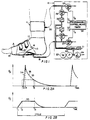
- a foot-pump element 10 is applied to the foot
- a tourniquet-calf element 11 is applied to the distal calf
- pneumatic actuating and control means 12 is connected to elements 10 and 11 for coordinated operation of the same, pursuant to a repetitive cycle, within the range 15 to 60 seconds.
- the foot-pump element 10 is suitably as described in said patents, so that simplified identification of parts will suffice for present purposes.
- the foot-pump element 10 comprises an inflatable bag or bladder 14 shaped for engagement with the sole of the foot and in the plantar arch, namely between the ball and the heel of the foot.
- a flexible pipe 15 connects bag 14 to the pneumatic supply and control means 12.
- the foot-pump element 10 further comprises a suitably padded wrap 16, embracing the bag 14 and over the instep 17 of the foot, and secured as by hook and loop fastening elements 18, to complete a circumferential tie at and round the mid-tarsal joint.
- the wrap 16 is shown covered by a cloth slipper 19 which covers the majority of the foot, leaving the toes exposed for the physician's inspection and reaction-testing of the involved foot.
- apparatus to be described at 12 operates rapidly to inflate the bag 14, which reacts against the circumferentially tied wrap 16 to apply pumping pressure to the sole of the foot while also urging the ball and heel of the foot away from each other, thus applying upward and spreading force and transiently flattening the plantar arch, as would occur if the foot were placed on the ground (i.e., body-weight bearing) during normal ambulation, thereby stimulating venous blood flow.
- the tourniquet-cuff element 11 may be a commercially available inflatable item, providing a circumferential tie around an inflatable bladder (not shown) which is preferably applied to the distal-calf region; the only exposed part of the inflatable cuff element 11 is its flexible supply pipe 20, which receives its inflation/deflation air supply from the control means 12.
- the pneumatic actuating and control means 12 of Fig. 1 operates from an accumulator 21 of pressurized air, which in the case of certain hospitals may be provided by a central source of suitably pressure-regulated supply.
- self-contained means 12 comprises an air pump 22, motor-driven at 23, with a relief valve 24 to determine a suitable upper limit of air pressure at accumulator 21.
- Pressurized air from the accumulator is connected for inflation-air delivery to the foot-pump supply pipe 15, via a first solenoid-operated valve 25 of the normally closed (NC) variety, and for inflation-air delivery to the tourniquet-cuff supply pipe 20, via a second normally closed solenoid-operated valve 26.
- NC normally closed
- Third and fourth normally closed solenoid-operated valves 27, 28 are respectively connected to the foot-pump and cuff pipes 15, 20 for controlled discharge to ambient air of the respective inflatable elements 10, 11.
- Programmable control means 30 will be understood to be presettable for the sequentially and suitably timed operation of the respective solenoid-operated valves, thus determining particular valve-opening events, suggested by time legends T 1 , T 3 , T 4 , T 6 which will be discussed in connection with the adjacent graphs of Figs. 2A and 2B to the same time scale.
- the graph of Fig. 2A displays, with some exaggeration for clarity, a representative inflation/deflation pressure pulse for the foot-pump element 10, and the graph of Fig. 2B is a similar display for a representative inflation/deflation pressure pulse for the tourniquet-cuff element 11.
- Separately identified times T 1 , T 2 , .... T 6 within each cycle of appliance operation serve to mark various coordinating events, as between foot-pump and tourniquet operation in the cycle, and the use of time designations T 1 to T 6 will be understood to indicate initiation of solenoid-valve actuations by means 30 in Fig. 1.
- separately adjustable variable orifices 31, 32 in the respective inflation lines to the foot-pump and cuff elements 10 and 11 will be understood to provide selective control of inflation rates for these elements.
- a representative cycle of appliance operation will commence with an actuating signal from control means 30 at time T 1 , thus opening valve 26 and initiating inflation of cuff 11.
- the flow of inflation air from accumulator 21 will preferably have been adjusted at 32 to provide a relatively slow rate of cuff inflation, so that, based on operational experience with the presssure of air from accumulator 21, an event T 2 determined by the program of means 30 will terminate the supply of accumulator air to cuff 11, by terminating the excitation of valve 26, thereby allowing valve 26 to return to its normally closed condition, with cuff 11 temporarily locked in inflated condition, at a level 33 of cuff pressure P c which will have been selected for the desired degree of local primary flow-restriction action on superficial veins, with relatively little flow-restricting action on deep veins.
- this level of cuff-inflation pressure is in the range of 30 to 100-mm Hg, being preferably in the range of 40 to 60-mm Hg; and the rate of cuff inflation is relatively slow, with cuff inflation accomplished within no less than one second.
- the solenoid valve 25 is actuated to open condition, thus admitting inflation air from accumulator 21 to the foot-pump bag, pursuant to the rate of air supply selected by prior adjustment of orifice 31.
- the rising slope 34 of inflation air to a peak foot-pump pressure in excess of the transiently locked-inflation pressure 33 of cuff 11 is desirably relatively rapid and in the range up to one second, being preferably in the range of 0.5 second or less. Achievement of peak foot-pump inflation pressure may be signalled by a pre-set pressure sensitive switch for terminating the actuating signal to solenoid valve 25, but in the circuitry shown in Fig.
- a peak-timing event at T 4 is operative (a) to terminate the actuating signal to valve 25 and (b) to initiate actuation of solenoid valve 27, for discharge of inflation air from foot-pump element 10, thus deflating the foot-pump bag 14 as rapidly as possible and substantially immediately upon achievement of peak foot-pump pressure.
- the curve 35 of resulting relief of foot-pump pressure has been exaggerated to enable better identification of subsequent events in the illustrative cycle of appliance operation.
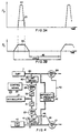
- Figs. 3A, 3B and 4 illustrate a modification wherein sensed pressure thresholds determine key events in the operative sequence of cuff and foot-pump actuation in each cycle.
- Pneumatic circuitry remains substantially as already described for Figs. 1, 2A and 2B, and therefore the same reference numbers are used, where applicable.
- Threshold sensing of a predetermined limit of cuff-inflation pressure is provided by pressure-sensitive switch means 40 in the air-supply line from solenoid valve 26 to cuff 11, and threshold sensing of a predetermined peaking limit of foot-pump pressure is provided by pressure-sensitive switch means 41 in the air-supply line from solenoid valve 25 to foot-pump 10.
- a differential-pressure switch 42 is connected for differential response to instantaneous cuff and foot-pump pressures, such that switch 42 may produce an electrical output signal in line 43 to solenoid valve 28 when foot-pump pressure has been sensed to drop to or below cuff-inflation pressure.
- Each pulsing cycle of Figs. 3A, 3B and 4 commences with an electrical actuating signal from control means 30 to solenoid valve 26, thus opening valve 26 and admitting inflation air to cuff 11 at a relatively slow rate determined by pre-set adjustment of orifice 32. Achievement of cuff inflation to the limit 33, predetermined at 40, will activate switch 40 (a) to terminate the actuated open condition of solenoid valve 26, and (b) to actuate solenoid valve 25 to open condition. Valve 25 then admits inflation air to foot-pump 10, at a relatively fast rate determined by pre-set adjustment of orifice 31.
- Fig. 4 The described operation of Fig. 4 will be seen to involve foot-pump deflation as soon as possible, once the peak-inflation level has been sensed by switch means 41. That being the case, the circuit of Fig. 4 can produce substantially the same coordination of cuff inflation and foot-pump inflation as was the case described in connection with Fig. 1. In certain situations, however, it may be desired to provide a selected relatively short period of holding the peak of foot-pump inflation pressure, before initiating the deflation process. It should be clear that such retention of foot-pump inflation in the case of Fig. 1 is achievable, merely by preselecting, at control means 30, a suitable interval between times T 3 and T 4 , for example, a selected interval of 1 to 5 seconds. In the case of Fig.
- a preselected peak-holding period of similar nature is selectively available by placing preselected timer terminals 47 (of control means 30) in series with a break in line 46, wherein such a break for series connection to terminals 47 is suggested by an "x" mark 48.
- the invention is also seen to have further application for the bed-ridden patient for whom the orthopedic surgeon may have ordered a foot to be suspended in elevated relation with respect to the heart.
- the plantar veins will necessarily be above heart elevation, thus inviting slow gravitational drainage of plantar veins and preventing such plantar-vein accumulation of blood as could be the subject of artificial foot-pump actuation.
- the cuff 11 particularly when located at the distal calf and inflated to the already indicated pressure range, and for the relatively long period up to 10 seconds, or for a period of at least 10 seconds prior to foot-pump actuation, will permit a desirable volume of plantar-vein accumulation by the time the foot-pump is activated at the rate and to the peak-pressure range already discussed.
- the cuff 11 should also be deflated, until need for renewed cuff inflation for the next cycle of coordinated cuff and foot-pump actuation.
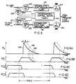
- Fig. 5 provides further schematic illustration of appliance components capable of various selected operations of cuff 11 in timed relation to foot-pump (14) operation, wherein programmable control means 130 is seen to determine the sequencing and/or interlacing of events governed by four solenoid valves, 125, 126, 127, 128, which may be of normally closed variety, as suggested by the symbol NC, it being understood that in Fig. 5 such flow-control devices as suitably adjusted variable orifices in the respective lines for these solenoid valves have been omitted, for simplification of the drawing. As shown in Fig.
- separate regulator valves 124, 124' operate from a single pressure-fluid source and are selectively adjustable to determine, respectively, a first and relatively low regulated pressure available for cuff inflation from a first accumulator 121, and a second and relatively elevated regulated pressure available for foot-pump inflation from a second accumulator 121'.
- valve (125) opening will be understood to effect relatively rapid inflation of foot-pump 14 via a relatively fast rise 134 to a peak of pressure (P p ), followed by a relatively gentle relaxation (135) from peak inflation pressure upon actuation of a venting solenoid 127 (with valve 125 in its NC condition); alternatively, with delayed actuation of the venting solenoid 127 (to the delayed extent ⁇ ), peak inflation pressure can be retained, and the gentle relaxation profile 135' will be correspondingly delayed.
- the arterial-flow enhancement properties of delayed retention of peak foot-pump inflation pressure are discussed in greater detail in U.S. Patent Re. 32,940.
- a concurrent program of cuff-11 inflation and relaxation is controlled by means 130 to supply cuff-inflation pressure fluid from accumulator 121 upon actuation of valve 126, the cuff inflation being shown in Fig. 6B to be retained until relaxation of foot-pump pressure reduces at least to the level of cuff-inflation pressure.
- the designation PC1 is adopted in Fig. 6B, for consideration alongside the foot-pump pressure profile of Fig. 6A, to illustrate use of the control apparatus of Fig. 5 to determine the DVT-reducing mode described in connection with Figs. 1, 2A and 2B.
- FIG. 5 Further uses of the control apparatus of Fig. 5 are illustrated by the respective cuff-pressure profiles PC2 and PC3 of Figs. 6C and 6D, which are particularly helpful in aid of a patient whose leg must be supported in an elevated state that necessarily places his foot, the foot-pump 14 and the cuff 11 above the elevation of his heart, as he lies in bed.
- Fig. 6C which presents the cuff-inflation pressure profile (PC2) to the same time scale as the foot-pump inflation profile (P p ) of Fig. 6A
- the inflation of cuff 11 occurs for a substantial fraction (e.g., one half) of the full cycle, as an event serving to "prime" the plantar veins immediately prior to foot-pump inflation, so that foot-pump action may have a fuller accumulation of blood in readiness for pumped venous return.
- the priming is fully completed at the instant of commencing foot-pump inflation, and in Fig.
- the profile (PC3) of cuff pressure inflation is seen to lap the foot-pump inflation profile (P p ) at least during the rise time of foot-pump inflation.
- the result of pumped venous-return effectiveness is substantially the same for Fig. 6C and for Fig. 6D, but the venting of cuff pressure is preferred to be substantially complete, as of the initiation of foot-pump inflation.
- Figs. 6C and 6D the criteria expressed in the above-noted patents for foot-pump operation are desirable, i.e., with inflation up to 225-mm Hg in less than one second, but the cuff-inflation pressure for "priming" should be in the order of 40 to 50-mm Hg, to allow the patient's heart action to supply the uphill flow for plantar-vein priming purposes.
- the reduced slope shown for all cuff inflations in Figs. 6B, 6C and 6D is a schematic indication of this fact.
- the peak of foot-pump pressure needed for the DVT treatment situation does not call for such elevated magnitudes as for a situation where DVT is not a problem.
- the DVT treatment wherein a thrombolizing agent is injected at the dorsum of the foot is relying upon the cuff to apply tourniquet action on the superficial veins so that deep veins can be more efficiently treated with the thrombolizing agent, in which case a cuff pressure in the order of 50-mm Hg and a peak foot-pump pressure in the range 100 to 200-mm Hg may be sufficient, and with a more gentle rising slope (e.g., to peak foot-pump pressure within 2 seconds or less).
Claims (19)
- Appareil médical destiné à traiter de manière thérapeutique et/ou prophylactique une anomalie de la circulation sanguine dans une jambe d'un patient, comprenant un manchon gonflable (11) unique destiné à être appliqué au mollet de la jambe, des premiers moyens (21, 26, 28, 32, 40, 121, 126) pour gonfler de manière transitoire ledit manchon (11) à un premier niveau de pression suffisant pour produire une action de pression de garrot locale sur le mollet, et pour permettre le dégonflage par la suite, une pompe à pied gonflable (10, 14, 16, 17, 18 et 19) destinée à appliquer une pression de gonflage principalement à la région plantaire entre la boule et le talon du pied, des seconds moyens (21, 25, 27, 31, 41, 121, 125) pour gonfler de manière transitoire ladite pompe à pied à une pression crête dépassant ledit premier niveau de pression, et pour permettre le dégonflage par la suite, et des moyens de commande actionnables de manière cyclique (30, 130) pour l'opération cyclique coordonnée de gonflage/dégonflage desdits premier et second moyens, et comprenant des moyens séparés d'alimentation en fluide sous pression uniquement dudit manchon gonflable (11) unique et de ladite pompe a pied gonflable (10, 14, 16, 17, 18 et 19) et caractérisé en ce que lesdits moyens de commande (30, 130) sont pourvus d'un dispositif de synchronisation préréglé pour déterminer les opérations séquentielles dudit manchon (11) et de ladite pompe à pied (10, 14, 16, 17, 18 et 19), ainsi que l'intervalle périodique du cycle récurrent, de sorte que :(a) initialement, via lesdits premiers moyens (21, 26, 28, 32, 40, 121, 126), ledit manchon (11) est alimenté en fluide sous pression pour maintenir de manière transitoire l'action de pression de garrot sur le mollet ;(b) via lesdits seconds moyens (21, 25, 27, 31, 41, 121, 125), ladite pompe à pied (10, 14, 16, 17, 18 et 19) est gonflée de manière transitoire à ladite pression crête dans la situation de ladite action de pression de garrot sur le mollet, et la pression de gonflage est relâchée une fois que ladite pression crête a été atteinte ; et(c) via lesdits premiers moyens (21, 25, 27, 31, 41, 121, 125), la pression du manchon de l'action de garrot est relâchée dans une relation synchronisée de manière sélective avec le gonflage et au moins avec le commencement du relâchement de la pression de la pompe à pied ;
le dispositif de synchronisation desdits moyens de commande (30, 130) fournissant un intervalle de temps d'achèvement de cycle entre lesdites opérations de commande via lesdits premiers moyens (21, 26, 28, 32, 40, 121, 126), et lesdits seconds moyens (21, 25, 27, 31, 41, 121, 125) avant le nouveau lancement de l'opération cyclique immédiatement suivante, dans lequel les cycles successifs se reproduisent à un intervalle périodique qui se situe dans la plage de 15 à 60 secondes. - Appareil médical selon la revendication 1, dans lequel lesdits moyens de commande (30, 130) comprennent des moyens susceptibles d'être commandés de manière sélective (21, 26, 28, 32, 40, 121, 126) pour le relâchement de la pression de la pompe à pied dans la plage sensiblement de zéro à cinq secondes qui suit l'obtention de ladite pression crête.
- Appareil médical selon la revendication 1, dans lequel lesdits moyens de commande (30, 130) comprennent des moyens susceptibles d'être commandés de manière sélective (21, 25, 27, 31, 40, 121, 125) pour gonfler et maintenir le gonflage dudit manchon (11) pendant un intervalle de temps qui dépasse l'intervalle de temps de gonflage de la pompe à pied et de relâchement de ladite pression crête.
- Appareil médical selon la revendication 1, pour traiter une jambe qui est supportée dans une position surélevée au dessus du niveau du support de lit par rapport au corps du patient, lesdits moyens de commande (30, 130) comprenant des moyens susceptibles d'être commandés de manière sélective (21, 25, 27, 31, 40, 121, 125) pour le gonflage et le maintien de la pression de garrot sur le mollet pendant un intervalle de temps immédiatement avant le gonflage de la pompe à pied.
- Appareil médical selon la revendication 1, pour traiter une condition de thrombose veineuse profonde dans la jambe à un emplacement qui est proximal par rapport à l'application du manchon au mollet, lesdits moyens de commande (30, 130) comprenant des moyens susceptibles d'être commandés de manière sélective (21, 25, 27, 31, 40, 121, 125) pour maintenir ladite pression de manchon sensiblement uniquement pendant une période de gonflage également de ladite pompe à pied à la pression crête et sensiblement de relâchement de la pression crête de ladite pompe à pied.
- Appareil médical selon la revendication 1, dans lequel lesdits moyens de commande (30, 130) comprennent des moyens susceptibles d'être commandés de manière sélective (21, 25, 27, 31, 40, 121, 125) pour maintenir la pression du manchon gonflé au moins dans une certaine concurrence synchronisée avec le gonflage de ladite pompe à pied à la pression crête et le relâchement de la pression crête de ladite pompe à pied.
- Appareil médical selon la revendication 1, dans lequel lesdits moyens de commande (30, 130) comprennent des moyens susceptibles d'être commandés de manière sélective (21, 25, 27, 31, 41, 121, 125) pour lancer le gonflage dudit manchon avant de lancer le gonflage de ladite pompe à pied et pour lancer le relâchement de la pression de la pompe à pied avant de lancer le relâchement de la pression du manchon.
- Appareil médical selon la revendication 2, dans lequel lesdits moyens susceptibles d'être commandés de manière sélective (21, 26, 28, 32, 40, 121, 126) comprennent des moyens pour sélectionner au moins un réglage parmi le groupe consistant en zéro seconde, une seconde, deux secondes, trois secondes, quatre secondes, et cinq secondes.
- Appareil médical selon la revendication 2, dans lequel l'intervalle périodique du cycle récurrent est sensiblement de 20 secondes.
- Appareil médical selon la revendication 1, dans lequel le gonflage transitoire dudit manchon (11) se fait à une vitesse plus lente que le gonflage transitoire de ladite pompe à pied (10, 14, 16, 12, 18 et 19).
- Appareil médical selon la revendication 1, dans lequel le gonflage transitoire de ladite pompe à pied (10, 14, 16, 17, 18 et 19) est effectué en moins d'une seconde.
- Appareil médical selon la revendication 1, dans lequel le gonflage transitoire de ladite pompe à pied (10, 14, 16, 17, 18 et 19) est effectué en moins de 0,5 seconde.
- Appareil médical selon la revendication 11, dans lequel le gonflage transitoire dudit manchon (11) n'est pas effectué en moins d'une seconde.
- Appareil médical selon la revendication 1, dans lequel le niveau de l'action de pression de garrot se situe dans la plage de 30 à 100 mm de Hg.
- Appareil médical selon la revendication 1, dans lequel le niveau de l'action de pression de garrot se situe dans la plage de 40 à 60 mm de Hg.
- Appareil médical selon la revendication 1, dans lequel le niveau de pression crête du gonflage de la pompe à pied se situe dans la plage qui va jusqu'à sensiblement 225 mm de Hg.
- Appareil médical selon la revendication 1, dans lequel le niveau de pression crête du gonflage de la pompe à pied est au moins sensiblement de 200 mm de Hg.
- Appareil médical selon la revendication 1, dans lequel lesdits moyens de commande (30, 130) comprennent des moyens sensibles à la pression (10, 42) connectés pour répondre à la pression instantanée du manchon pour lancer le gonflage de ladite pompe à pied (10, 14, 16, 17, 18, 19) lors de l'obtention détectée dudit premier niveau de pression du gonflage du manchon.
- Appareil médical selon la revendication 1, dans lequel lesdits moyens de commande (30, 130) comprennent des moyens sensibles à la pression (10, 42) connectés pour répondre à la différence entre la pression du manchon et la pression instantanée de la pompe à pied pour lancer le dégonflage dudit manchon (11) lors de la réduction détectée de la pression instantanée de la pompe à pied au niveau instantané de la pression du manchon.
Applications Claiming Priority (3)
| Application Number | Priority Date | Filing Date | Title |
|---|---|---|---|
| US98058092A | 1992-11-23 | 1992-11-23 | |
| US980580 | 1992-11-23 | ||
| PCT/GB1993/002401 WO1994012141A1 (fr) | 1992-11-23 | 1993-11-22 | Appareil de stimulation de la circulation sanguine |
Publications (2)
| Publication Number | Publication Date |
|---|---|
| EP0757552A1 EP0757552A1 (fr) | 1997-02-12 |
| EP0757552B1 true EP0757552B1 (fr) | 2000-05-03 |
Family
ID=25527679
Family Applications (1)
| Application Number | Title | Priority Date | Filing Date |
|---|---|---|---|
| EP94900911A Expired - Lifetime EP0757552B1 (fr) | 1992-11-23 | 1993-11-22 | Appareil de stimulation de la circulation sanguine |
Country Status (7)
| Country | Link |
|---|---|
| EP (1) | EP0757552B1 (fr) |
| JP (1) | JP3588465B2 (fr) |
| AT (1) | ATE192326T1 (fr) |
| AU (1) | AU688742B2 (fr) |
| CA (1) | CA2109736C (fr) |
| DE (1) | DE69328570T2 (fr) |
| WO (1) | WO1994012141A1 (fr) |
Families Citing this family (5)
| Publication number | Priority date | Publication date | Assignee | Title |
|---|---|---|---|---|
| DE19524380C2 (de) * | 1995-07-04 | 1997-10-09 | Steinweg Friedhelm Dr Med | Massageeinrichtung, insbesondere zum Einsatz in der Entstauungstherapie |
| WO2003053323A2 (fr) * | 2001-12-11 | 2003-07-03 | Noclots Limited | Perfectionnements relatifs a des dispositifs de compression des mollets |
| US7384636B2 (en) | 2003-03-31 | 2008-06-10 | Kabushiki Kaisha Hayashibara Seibutsu Kagaku Kenkyujo | Polypeptide |
| CN103349606B (zh) * | 2013-07-09 | 2016-03-30 | 柴小青 | 便携式气动抗下肢深静脉血栓按摩器 |
| CN114306017A (zh) * | 2021-12-28 | 2022-04-12 | 深圳普门科技股份有限公司 | 抗栓系统及其控制方法、装置和可读存储介质 |
Family Cites Families (4)
| Publication number | Priority date | Publication date | Assignee | Title |
|---|---|---|---|---|
| SU986421A1 (ru) * | 1980-12-04 | 1983-01-07 | Всесоюзный научно-исследовательский и испытательный институт медицинской техники | Устройство дл наружной контрпульсации |
| ATE49114T1 (de) * | 1983-06-22 | 1990-01-15 | Novamedix Ltd | Medizinisches geraet zur ausuebung einer pumpwirkung auf die fusssohle. |
| US4624244A (en) * | 1984-10-15 | 1986-11-25 | Taheri Syde A | Device for aiding cardiocepital venous flow from the foot and leg of a patient |
| US5186163A (en) * | 1991-11-25 | 1993-02-16 | The Kendall Company | Compression device |
-
1993
- 1993-11-22 WO PCT/GB1993/002401 patent/WO1994012141A1/fr active IP Right Grant
- 1993-11-22 JP JP51289494A patent/JP3588465B2/ja not_active Expired - Fee Related
- 1993-11-22 DE DE69328570T patent/DE69328570T2/de not_active Expired - Lifetime
- 1993-11-22 AT AT94900911T patent/ATE192326T1/de not_active IP Right Cessation
- 1993-11-22 EP EP94900911A patent/EP0757552B1/fr not_active Expired - Lifetime
- 1993-11-22 AU AU55683/94A patent/AU688742B2/en not_active Expired
- 1993-11-23 CA CA002109736A patent/CA2109736C/fr not_active Expired - Lifetime
Also Published As
| Publication number | Publication date |
|---|---|
| DE69328570T2 (de) | 2001-01-04 |
| EP0757552A1 (fr) | 1997-02-12 |
| AU688742B2 (en) | 1998-03-19 |
| CA2109736C (fr) | 2004-08-10 |
| AU5568394A (en) | 1994-06-22 |
| DE69328570D1 (de) | 2000-06-08 |
| WO1994012141A1 (fr) | 1994-06-09 |
| JP3588465B2 (ja) | 2004-11-10 |
| JPH08504118A (ja) | 1996-05-07 |
| CA2109736A1 (fr) | 1994-05-24 |
| ATE192326T1 (de) | 2000-05-15 |
Similar Documents
| Publication | Publication Date | Title |
|---|---|---|
| US5584798A (en) | Medical inflatable cuff appliance | |
| US5669872A (en) | Method for focused delivery of venous flow for artificial impluse compression of an anatomical foot pump | |
| EP0150553B1 (fr) | Appareil médical pour appliquer une action de pompage à la plante du pied | |
| US6007559A (en) | Vascular assist methods and apparatus | |
| US5117812A (en) | Segmented compression device for the limb | |
| US5968073A (en) | Methods and apparatus for applying pressure | |
| EP2314268B1 (fr) | Système de traitement par compression | |
| US4696289A (en) | Method of promoting venous pump action | |
| US4721101A (en) | Medical appliance | |
| EP0707468B1 (fr) | Appareil pour fournir une compression intermittente therapeutique pour diminuer les risques de thrombose des veines profondes | |
| US9044372B2 (en) | Compression device for the limb | |
| DK2079419T3 (en) | compression System | |
| US6463934B1 (en) | Method for providing enhanced blood circulation | |
| US20120209153A1 (en) | Deep vein thrombosis therapy device | |
| JP2003500167A (ja) | 深在静脈血栓症(dvt)予防のためのポータブル自蔵装置 | |
| AU2001264859A1 (en) | Method for providing enhanced blood circulation | |
| US7207959B1 (en) | Thrombus prevention apparatus and methods | |
| EP0757552B1 (fr) | Appareil de stimulation de la circulation sanguine | |
| GB2141938A (en) | Medical appliance | |
| US20210378907A1 (en) | Thigh-Only Deep Vein Thrombosis Device and Double Pulsation Method of Using Device | |
| CA1291386C (fr) | Appareil a vocation medicale | |
| GB2285749A (en) | Apparatus for applying limb compression |
Legal Events
| Date | Code | Title | Description |
|---|---|---|---|
| PUAI | Public reference made under article 153(3) epc to a published international application that has entered the european phase |
Free format text: ORIGINAL CODE: 0009012 |
|
| 17P | Request for examination filed |
Effective date: 19950906 |
|
| AK | Designated contracting states |
Kind code of ref document: A1 Designated state(s): AT BE CH DE DK ES FR GB IT LI NL SE |
|
| 17Q | First examination report despatched |
Effective date: 19970304 |
|
| RAP1 | Party data changed (applicant data changed or rights of an application transferred) |
Owner name: NOVAMEDIX DISTRIBUTION LTD. |
|
| GRAG | Despatch of communication of intention to grant |
Free format text: ORIGINAL CODE: EPIDOS AGRA |
|
| GRAG | Despatch of communication of intention to grant |
Free format text: ORIGINAL CODE: EPIDOS AGRA |
|
| GRAH | Despatch of communication of intention to grant a patent |
Free format text: ORIGINAL CODE: EPIDOS IGRA |
|
| GRAH | Despatch of communication of intention to grant a patent |
Free format text: ORIGINAL CODE: EPIDOS IGRA |
|
| GRAA | (expected) grant |
Free format text: ORIGINAL CODE: 0009210 |
|
| AK | Designated contracting states |
Kind code of ref document: B1 Designated state(s): AT BE CH DE DK ES FR GB IT LI NL SE |
|
| PG25 | Lapsed in a contracting state [announced via postgrant information from national office to epo] |
Ref country code: LI Free format text: LAPSE BECAUSE OF FAILURE TO SUBMIT A TRANSLATION OF THE DESCRIPTION OR TO PAY THE FEE WITHIN THE PRESCRIBED TIME-LIMIT Effective date: 20000503 Ref country code: ES Free format text: THE PATENT HAS BEEN ANNULLED BY A DECISION OF A NATIONAL AUTHORITY Effective date: 20000503 Ref country code: CH Free format text: LAPSE BECAUSE OF FAILURE TO SUBMIT A TRANSLATION OF THE DESCRIPTION OR TO PAY THE FEE WITHIN THE PRESCRIBED TIME-LIMIT Effective date: 20000503 Ref country code: AT Free format text: LAPSE BECAUSE OF FAILURE TO SUBMIT A TRANSLATION OF THE DESCRIPTION OR TO PAY THE FEE WITHIN THE PRESCRIBED TIME-LIMIT Effective date: 20000503 |
|
| REF | Corresponds to: |
Ref document number: 192326 Country of ref document: AT Date of ref document: 20000515 Kind code of ref document: T |
|
| REG | Reference to a national code |
Ref country code: CH Ref legal event code: EP |
|
| REF | Corresponds to: |
Ref document number: 69328570 Country of ref document: DE Date of ref document: 20000608 |
|
| ITF | It: translation for a ep patent filed |
Owner name: JACOBACCI & PERANI S.P.A. |
|
| PG25 | Lapsed in a contracting state [announced via postgrant information from national office to epo] |
Ref country code: SE Free format text: LAPSE BECAUSE OF FAILURE TO SUBMIT A TRANSLATION OF THE DESCRIPTION OR TO PAY THE FEE WITHIN THE PRESCRIBED TIME-LIMIT Effective date: 20000803 Ref country code: DK Free format text: LAPSE BECAUSE OF FAILURE TO SUBMIT A TRANSLATION OF THE DESCRIPTION OR TO PAY THE FEE WITHIN THE PRESCRIBED TIME-LIMIT Effective date: 20000803 |
|
| ET | Fr: translation filed | ||
| REG | Reference to a national code |
Ref country code: CH Ref legal event code: PL |
|
| PLBE | No opposition filed within time limit |
Free format text: ORIGINAL CODE: 0009261 |
|
| STAA | Information on the status of an ep patent application or granted ep patent |
Free format text: STATUS: NO OPPOSITION FILED WITHIN TIME LIMIT |
|
| 26N | No opposition filed | ||
| REG | Reference to a national code |
Ref country code: GB Ref legal event code: IF02 |
|
| PGFP | Annual fee paid to national office [announced via postgrant information from national office to epo] |
Ref country code: DE Payment date: 20101126 Year of fee payment: 18 |
|
| PGFP | Annual fee paid to national office [announced via postgrant information from national office to epo] |
Ref country code: IT Payment date: 20101124 Year of fee payment: 18 Ref country code: GB Payment date: 20101124 Year of fee payment: 18 |
|
| PGFP | Annual fee paid to national office [announced via postgrant information from national office to epo] |
Ref country code: FR Payment date: 20111128 Year of fee payment: 19 Ref country code: NL Payment date: 20111129 Year of fee payment: 19 |
|
| PGFP | Annual fee paid to national office [announced via postgrant information from national office to epo] |
Ref country code: BE Payment date: 20111124 Year of fee payment: 19 |
|
| BERE | Be: lapsed |
Owner name: *NOVAMEDIX DISTRIBUTION LTD Effective date: 20121130 |
|
| REG | Reference to a national code |
Ref country code: NL Ref legal event code: V1 Effective date: 20130601 |
|
| GBPC | Gb: european patent ceased through non-payment of renewal fee |
Effective date: 20121122 |
|
| REG | Reference to a national code |
Ref country code: FR Ref legal event code: ST Effective date: 20130731 |
|
| PG25 | Lapsed in a contracting state [announced via postgrant information from national office to epo] |
Ref country code: IT Free format text: LAPSE BECAUSE OF NON-PAYMENT OF DUE FEES Effective date: 20121122 Ref country code: NL Free format text: LAPSE BECAUSE OF NON-PAYMENT OF DUE FEES Effective date: 20130601 Ref country code: BE Free format text: LAPSE BECAUSE OF NON-PAYMENT OF DUE FEES Effective date: 20121130 |
|
| REG | Reference to a national code |
Ref country code: DE Ref legal event code: R119 Ref document number: 69328570 Country of ref document: DE Effective date: 20130601 |
|
| PG25 | Lapsed in a contracting state [announced via postgrant information from national office to epo] |
Ref country code: DE Free format text: LAPSE BECAUSE OF NON-PAYMENT OF DUE FEES Effective date: 20130601 |
|
| PG25 | Lapsed in a contracting state [announced via postgrant information from national office to epo] |
Ref country code: GB Free format text: LAPSE BECAUSE OF NON-PAYMENT OF DUE FEES Effective date: 20121122 Ref country code: FR Free format text: LAPSE BECAUSE OF NON-PAYMENT OF DUE FEES Effective date: 20121130 |