EP0757394A1 - Battery having an over-loading preventing device - Google Patents
Battery having an over-loading preventing device Download PDFInfo
- Publication number
- EP0757394A1 EP0757394A1 EP96305325A EP96305325A EP0757394A1 EP 0757394 A1 EP0757394 A1 EP 0757394A1 EP 96305325 A EP96305325 A EP 96305325A EP 96305325 A EP96305325 A EP 96305325A EP 0757394 A1 EP0757394 A1 EP 0757394A1
- Authority
- EP
- European Patent Office
- Prior art keywords
- cap
- cover
- case
- battery
- switching means
- Prior art date
- Legal status (The legal status is an assumption and is not a legal conclusion. Google has not performed a legal analysis and makes no representation as to the accuracy of the status listed.)
- Withdrawn
Links
- 229910001285 shape-memory alloy Inorganic materials 0.000 claims abstract description 46
- 229910001000 nickel titanium Inorganic materials 0.000 claims abstract description 5
- 239000003792 electrolyte Substances 0.000 claims description 26
- 238000005452 bending Methods 0.000 claims description 23
- 238000004804 winding Methods 0.000 claims description 21
- 230000002093 peripheral effect Effects 0.000 claims description 5
- 238000007789 sealing Methods 0.000 claims description 5
- 230000004044 response Effects 0.000 claims description 2
- 229910052744 lithium Inorganic materials 0.000 abstract description 30
- WHXSMMKQMYFTQS-UHFFFAOYSA-N Lithium Chemical compound [Li] WHXSMMKQMYFTQS-UHFFFAOYSA-N 0.000 abstract description 29
- 238000013021 overheating Methods 0.000 abstract description 11
- 238000004880 explosion Methods 0.000 abstract description 6
- NUJOXMJBOLGQSY-UHFFFAOYSA-N manganese dioxide Chemical compound O=[Mn]=O NUJOXMJBOLGQSY-UHFFFAOYSA-N 0.000 description 6
- 229910052751 metal Inorganic materials 0.000 description 6
- 239000002184 metal Substances 0.000 description 6
- 238000013459 approach Methods 0.000 description 5
- 239000000463 material Substances 0.000 description 5
- 238000004519 manufacturing process Methods 0.000 description 4
- OKTJSMMVPCPJKN-UHFFFAOYSA-N Carbon Chemical compound [C] OKTJSMMVPCPJKN-UHFFFAOYSA-N 0.000 description 3
- 229910052782 aluminium Inorganic materials 0.000 description 3
- XAGFODPZIPBFFR-UHFFFAOYSA-N aluminium Chemical compound [Al] XAGFODPZIPBFFR-UHFFFAOYSA-N 0.000 description 3
- 239000011230 binding agent Substances 0.000 description 3
- 229910052799 carbon Inorganic materials 0.000 description 3
- 230000008602 contraction Effects 0.000 description 3
- 239000011888 foil Substances 0.000 description 3
- 239000007789 gas Substances 0.000 description 3
- 230000009257 reactivity Effects 0.000 description 3
- 230000003213 activating effect Effects 0.000 description 2
- 239000000203 mixture Substances 0.000 description 2
- 229910045601 alloy Inorganic materials 0.000 description 1
- 239000000956 alloy Substances 0.000 description 1
- 239000010406 cathode material Substances 0.000 description 1
- 239000007769 metal material Substances 0.000 description 1
- 150000002739 metals Chemical class 0.000 description 1
- 238000000034 method Methods 0.000 description 1
- 239000005486 organic electrolyte Substances 0.000 description 1
- RUOJZAUFBMNUDX-UHFFFAOYSA-N propylene carbonate Chemical compound CC1COC(=O)O1 RUOJZAUFBMNUDX-UHFFFAOYSA-N 0.000 description 1
- 230000035939 shock Effects 0.000 description 1
Images


Classifications
-
- H—ELECTRICITY
- H01—ELECTRIC ELEMENTS
- H01M—PROCESSES OR MEANS, e.g. BATTERIES, FOR THE DIRECT CONVERSION OF CHEMICAL ENERGY INTO ELECTRICAL ENERGY
- H01M50/00—Constructional details or processes of manufacture of the non-active parts of electrochemical cells other than fuel cells, e.g. hybrid cells
- H01M50/50—Current conducting connections for cells or batteries
- H01M50/572—Means for preventing undesired use or discharge
- H01M50/574—Devices or arrangements for the interruption of current
- H01M50/581—Devices or arrangements for the interruption of current in response to temperature
-
- H—ELECTRICITY
- H01—ELECTRIC ELEMENTS
- H01M—PROCESSES OR MEANS, e.g. BATTERIES, FOR THE DIRECT CONVERSION OF CHEMICAL ENERGY INTO ELECTRICAL ENERGY
- H01M50/00—Constructional details or processes of manufacture of the non-active parts of electrochemical cells other than fuel cells, e.g. hybrid cells
- H01M50/50—Current conducting connections for cells or batteries
- H01M50/572—Means for preventing undesired use or discharge
-
- H—ELECTRICITY
- H01—ELECTRIC ELEMENTS
- H01M—PROCESSES OR MEANS, e.g. BATTERIES, FOR THE DIRECT CONVERSION OF CHEMICAL ENERGY INTO ELECTRICAL ENERGY
- H01M10/00—Secondary cells; Manufacture thereof
- H01M10/04—Construction or manufacture in general
-
- H—ELECTRICITY
- H01—ELECTRIC ELEMENTS
- H01M—PROCESSES OR MEANS, e.g. BATTERIES, FOR THE DIRECT CONVERSION OF CHEMICAL ENERGY INTO ELECTRICAL ENERGY
- H01M10/00—Secondary cells; Manufacture thereof
- H01M10/05—Accumulators with non-aqueous electrolyte
- H01M10/052—Li-accumulators
-
- H—ELECTRICITY
- H01—ELECTRIC ELEMENTS
- H01M—PROCESSES OR MEANS, e.g. BATTERIES, FOR THE DIRECT CONVERSION OF CHEMICAL ENERGY INTO ELECTRICAL ENERGY
- H01M10/00—Secondary cells; Manufacture thereof
- H01M10/42—Methods or arrangements for servicing or maintenance of secondary cells or secondary half-cells
-
- H—ELECTRICITY
- H01—ELECTRIC ELEMENTS
- H01M—PROCESSES OR MEANS, e.g. BATTERIES, FOR THE DIRECT CONVERSION OF CHEMICAL ENERGY INTO ELECTRICAL ENERGY
- H01M50/00—Constructional details or processes of manufacture of the non-active parts of electrochemical cells other than fuel cells, e.g. hybrid cells
- H01M50/50—Current conducting connections for cells or batteries
- H01M50/572—Means for preventing undesired use or discharge
- H01M50/574—Devices or arrangements for the interruption of current
- H01M50/578—Devices or arrangements for the interruption of current in response to pressure
-
- H—ELECTRICITY
- H01—ELECTRIC ELEMENTS
- H01M—PROCESSES OR MEANS, e.g. BATTERIES, FOR THE DIRECT CONVERSION OF CHEMICAL ENERGY INTO ELECTRICAL ENERGY
- H01M2200/00—Safety devices for primary or secondary batteries
-
- H—ELECTRICITY
- H01—ELECTRIC ELEMENTS
- H01M—PROCESSES OR MEANS, e.g. BATTERIES, FOR THE DIRECT CONVERSION OF CHEMICAL ENERGY INTO ELECTRICAL ENERGY
- H01M2200/00—Safety devices for primary or secondary batteries
- H01M2200/20—Pressure-sensitive devices
-
- H—ELECTRICITY
- H01—ELECTRIC ELEMENTS
- H01M—PROCESSES OR MEANS, e.g. BATTERIES, FOR THE DIRECT CONVERSION OF CHEMICAL ENERGY INTO ELECTRICAL ENERGY
- H01M50/00—Constructional details or processes of manufacture of the non-active parts of electrochemical cells other than fuel cells, e.g. hybrid cells
- H01M50/50—Current conducting connections for cells or batteries
- H01M50/572—Means for preventing undesired use or discharge
- H01M50/574—Devices or arrangements for the interruption of current
-
- Y—GENERAL TAGGING OF NEW TECHNOLOGICAL DEVELOPMENTS; GENERAL TAGGING OF CROSS-SECTIONAL TECHNOLOGIES SPANNING OVER SEVERAL SECTIONS OF THE IPC; TECHNICAL SUBJECTS COVERED BY FORMER USPC CROSS-REFERENCE ART COLLECTIONS [XRACs] AND DIGESTS
- Y02—TECHNOLOGIES OR APPLICATIONS FOR MITIGATION OR ADAPTATION AGAINST CLIMATE CHANGE
- Y02E—REDUCTION OF GREENHOUSE GAS [GHG] EMISSIONS, RELATED TO ENERGY GENERATION, TRANSMISSION OR DISTRIBUTION
- Y02E60/00—Enabling technologies; Technologies with a potential or indirect contribution to GHG emissions mitigation
- Y02E60/10—Energy storage using batteries
Definitions
- the present invention relates to a battery, and more particularly but not exclusively to a lithium battery.
- a lithium battery is generally used as an electric power source for a portable device such as a camcorder or the like since the battery is easy to carry with and mount on the device.
- the lithium battery has a lithium metal as a cathode activating material, and a manganese dioxide as an anode activating material.
- the lithium battery also has an electrolyte which includes an inorganic electrolyte dissolved in the nonaqueous solution containing propylene carbonate.
- FIG. 1 is an exploded perspective view which shows a conventional lithium battery.
- FIG. 2 is a cross sectional view which shows an assembled state of the battery as shown in FIG. 1.
- FIG. 3 is an enlarged cross sectional view of portion A shown in FIG. 2.
- a lithium battery 100 has a case 60.
- a bending portion 62 is formed at an upper portion of case 60 and case 60 below bending portion 62 is filled with an electrolyte 70.
- Current is generated by the reaction of electrolyte 70, and is thereby applied to a load through a positive electrode lead 51 and a negative electrode lead 52.
- negative electrode lead 52 is bent to make contact with the inner bottom surface of case 60.
- a cover 30 is placed at an upper portion of case 60. Cover 30 has a through hole 31 formed at the central portion thereof.
- Positive electrode lead 51 is bent to make contact with cover 30.
- Aluminum foil 32 and a ring plate 33 comprised of plastic, are stacked in cover 30. In the case of an explosion of electrolyte 70, aluminum foil 32 is easily torn so that the gases generated by the explosion are vented.
- a positive temperature coefficient (PTC) thermistor 20 is positioned on cover 30.
- the resistance of PTC thermistor 20 approaches infinity when the temperature rises up over a predetermined value, e.g., 80 degree Celsius.
- PTC thermistor has an opening 21 corresponding to through hole 31 of cover 30 at the center portion of PTC thermistor 20.
- a cap 10 which functions as a positive electrode terminal, is positioned on PTC thermistor 20.
- a vent hole 11 is formed at the center portion of cap 10.
- PTC thermistor 20 is manufactured by mixing various metals. When the temperature of the battery rises up over 80 degree Celsius, the resistance of PTC thermistor 20 approaches infinity, thereby causing the current to be cut off.
- a gasket 40 for sealing the interior of case 60 is provided between the inner surface of case 60 and the stacked cap 10, PTC thermistor 20, and cover 30, and surrounds stacked cap 10, PTC thermistor 20, and cover 30.
- Case 60 is made of a metal material which is conductive, and makes contact with negative electrode lead 52 so as to function as a negative electrode terminal.
- the upper end of case 60 is bent towards the interior of case 60, so gasket 40 is fixed at a position between case 60 and stacked cap 10, PTC thermistor 20, and cover 30.
- a winding assembly 50 chemically reacts with electrolyte 70 in case 60, thereby generating current.
- Winding assembly 50 is manufactured by applying a mixture of manganese dioxide and carbon by means of a binder to a metal net of expanded metal. Current is generated by the reaction of winding assembly 50 with electrolyte 70, and is applied to a load through positive and negative electrode leads 51 and 52.
- lithium battery 100 By using lithium battery 100 as above, current is generated by the reaction of winding assembly 50 with electrolyte 70, and the current generated in this manner is applied to a potable electrical device through positive and negative electrode leads 51 and 52.
- lithium battery 100 there is a possibility of explosion of electrolyte 70 due to a high temperature or an external shock.
- aluminum foil 33 is torn so that the expanded gases can be exhausted outside case 60 through both through hole 31 of PTC thermistor 20 and vent hole 11 of cap 10.
- the conventional lithium battery 100 provides PTC thermistor 20 on cover 30 to prevent the overheating of battery 100.
- the temperature of electrolyte 70 rises due to a short which occurs therein, the heat is transferred to PTC thermistor 20.
- the resistance of PCT thermistor 20, as above-mentioned approaches infinity if the temperature rises up over 80°C. Therefore, when the temperature in lithium battery 100 exceeds a predetermined value, the current which flows though PTC thermistor 20 is cut off so that the overheating of lithium battery 100 can be prevented.
- PTC element 20 of lithium battery 100 are generally expensive, which increases the manufacturing cost of battery 100. Further, since the contraction and expansion rates of PTC element 20 is not uniform, the conventional battery has poor reliability. Also, the response speed thereof with respect to the heat is slow.
- a battery comprising a case for containing electrolyte therein; a winding assembly which reacts with the electrolyte so as to generate current; a cover which makes contact with said winding assembly so as to allow the current to flow; a cap which is positioned on said cover and has an electrode portion for applying the current to a load; and a switching means which makes contact with both said cover and said cap between said cover and said cap so as to electrically connect said cover with said cap, and which responds to temperature to electrically disconnect said cover from said cap.
- a gasket is provided for fixing the cover, the cap, and the switching means at an upper portion of the case, and for sealing a clearance (or gap) between the stacked cover, the cap, and the switching means, and an inner surface of the case.
- An inward protrusion which protrudes towards the interior of the case is formed at an upper portion of the case, and the gasket is fixed between the inward protrusion and a bending portion formed at an upper end of the case.
- the gasket has a first bending portion formed at an upper end of the gasket, a protrusion, and a second bending portion formed at a lower end of the gasket, the first bending portion being bent towards the interior of the case so as to fix the cap, the protrusion protruding towards the interior of the case below the first bending portion so as to fix the cap together with the first bending portion, and the second bending portion being bent towards the interior of the case so as to mount the cover.
- the switching means is preferably a shape-memory alloy spring which can contract or expand within a temperature range of -50 to 100 degrees Celsius as the temperature of the battery rises and falls.
- the shape-memory alloy may be comprised of a nickel-titanium alloy.
- the switching means has a disk shape of uniform thickness, a peripheral portion which makes contact with the cover so as to allow electric current to flow, and a semi-spherical protrusion formed at the center of the switching means so as to contact with a bottom of the cap, so that when the battery is overheated, the protrusion becomes flat and thereby is physically separated from the cap so as to electrically disconnect the cap from the cover.
- Two recesses which have substantially the same diameters as a diameter of the semi-spherical protrusion of the shape-memory alloy spring, are respectively formed at upper and lower surface portions of the cover.
- the cap has a cylindrical protrusion wherein a vent hole is formed at a center of the cap, the switching means has a disk shape of uniform thickness, a peripheral portion of the switching means makes contact with the cover so as to allow the current to flow, and a semi-spherical protrusion is formed at a center of the switching means so as to make contact with the bottom of the protrusion of the cap.
- the heat is transferred through the cover to the semi-spherical protrusion of the shape-memory alloy spring. If the temperature of the shape-memory alloy spring rises above a predetermined value, e.g., 80 degree Celsius, the semi-spherical protrusion of the shape-memory alloy spring becomes flat, so that it is physically separated from the bottom of the cap, thereby causing the current to be cut off.
- a predetermined value e.g. 80 degree Celsius
- the shape-memory alloy spring recovers its shape, so that the semi-spherical protrusion makes contact with the bottom of the cap, thereby allowing the current to flow. Therefore, the semi-spherical protrusion of the shape-memory alloy spring repeatedly contracts and expands so that the battery of the present invention cuts off the current, thereby preventing the overheating thereof. Precise switching operation of the current prevents the overheating of the lithium battery.
- a battery comprising a case for containing electrolyte therein; a winding assembly which reacts with the electrolyte so as to generate current; a cover which makes contact with said winding assembly so as to allow the current to flow; a cap which is positioned on said cover and has an electrode portion for applying the current to a load; a switching means comprising a shape-memory alloy spring which makes contact with both said cover and said cap between said cover and said cap so as to electrically connect said cover with said cap, and which responds to temperature to physically separate from said cap so as to electrically disconnect said cover from said cap, said shape-memory alloy spring contracting and expanding within a predetermined temperature range; and a gasket for fixing said cover, said cap, and said switching means at an upper portion of said case, and for sealing a clearance between said cover, said cap, and said switching means, and an inner surface of said case.
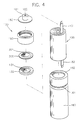
- FIG. 4 is an exploded perspective view of the lithium battery according to an embodiment of the present invention.
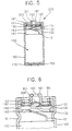
- FIG. 5 is a cross sectional view for showing the assembled state of the battery shown in FIG. 4.
- FIG. 6 is an enlarged cross sectional view of the upper portion of the lithium battery as shown in FIG. 5.
- a lithium battery 200 includes a case 160.
- Case 160 has a cylindrical shape, and contains electrolyte 170 therein.
- a bending portion 162 is formed at the upper end of case 200, which is bent towards the interior of case 200.
- An inward protrusion 161 is formed at the upper portion of case 200, which is bent so that it protrudes towards the interior of case 200.
- Case 200 is comprised of a material of high conductivity.
- the bottom surface of case 200 functions as a negative electrode contacting portion.
- a winding assembly 150 is provided in case 170, and is immersed in electrolyte 170.
- Winding assembly 150 is comprised of a material which reacts chemically with electrolyte 170 so as to generate current. That is, winding assembly 150 is manufactured by applying the mixture of manganese dioxide and carbon by means of a binder to a metal net of an expanded metal. Winding assembly 150 reacts with electrolyte 170 to thereby generate current.
- Negative and positive electrode leads 152 and 151 are attached to the lower and upper portions of winding assembly 150, respectively.
- Negative electrode lead 152 which is attached to the lower portion of winding assembly 150, makes contact with the inner bottom surface of case 200, which functions as a negative electrode terminal.
- the current generated by the reaction of winding assembly 150 with electrolyte 170 flows through positive and negative electrode leads 151 and 152 to outside the lithium battery.
- a cover 130, a shape-memory alloy spring 300, and a cap 180 are stacked in series at the upper portion of cover 130 between bending portion 162 and inward protrusion 161.
- a gasket 190 is provided between the upper inner surface of case 160 and the stacked cover 130, shape-memory alloy spring 300, and cap 180, at a position between bending portion 162 and inward protrusion 161 so as to fix cover 130, shape-memory alloy spring 300, and cap 180.
- Gasket 190 also seals the clearance between the upper inner surface of case 160 and stacked cover 130, shape-memory alloy spring 300, and cap 180.
- Upper and lower bending portions 192 and 193 are respectively formed at the upper and lower ends of gasket 190, which are bent towards the interior of case 200.
- An inward protrusion 191 is formed at the position below the upper bending portion 192.
- Cap 180 is fixed between upper bending portion 192 and inward protrusion 191.
- Cover 130 is mounted on lower bending portion 193 (that is, lower bending portion supports cover 130).
- Cap 180 is comprised of a metal.
- a cylindrical protrusion 181 is formed at the center of cap 180, which functions as a positive electrode terminal.
- a vent hole 182 is formed at the center of cylindrical protrusion 181. The gas generated either by the reaction of electrolyte 170 and winding assembly 150 or by an explosion is exhausted outside case 200 through vent hole 182.
- Shape-memory alloy spring 300 is provided below cap 180, which makes contact with the bottom portion of cylindrical protrusion 181.
- Shape-memory alloy spring 300 has a disk shape of uniform thickness.
- the peripheral portion of shape-memory alloy spring 300 makes contact with cover 130 so as to allow the electric current to flow.
- Semi-spherical protrusion 301 is formed at the center of shape-memory alloy spring 300.
- the upper portion of semi-spherical protrusion 301 of shape-memory alloy spring 300 makes contact with the bottom of cylindrical protrusion 181 of cap 180.
- shape-memory alloy spring 300 between cover 130 and cap 180 makes contact with both cover 130 and cap 180, thereby electrically connecting cover 130 with cap 180.
- shape-memory alloy spring 300 When the temperature of lithium battery 200 rises above a predetermined value because of overheating, semi-spherical protrusion 301 of shape-memory alloy spring 300 becomes flatter, as shown by the dotted line in FIG. 6, so that shape-memory alloy spring 300 is separated (physically apart) from the bottom of cylindrical protrusion 181. As a result, cover 130 and cap 180 are electrically disconnected from each other.
- Shape-memory alloy spring 300 is comprised of a nickel-titanium alloy so as to contract or expand within the temperature range of -50 to 100 degrees Celsius.
- U.S. Pat. No. 5,092,901 (issued to Hunter et al.) discloses an example of such a memory-shape alloy.
- EP-A1-0 045 250 discloses a method of manufacturing a motor by using a nickel-titanium alloy.
- Shape-memory alloy spring 300 according to the present invention can be manufactured easily by the methods disclosed in the above-mentioned publications.
- the contraction/expansion operation temperature can be preliminary memorized during the manufacturing process of the shape-memory alloy spring.
- Semi-spherical protrusion 301 of shape-memory alloy spring 300 maintains the contact with the bottom of cap 180 during a normal condition when the temperature is not varied, and is separated from cap 180 when the temperature is above a predetermined temperature, e.g., 80 degree Celsius by the contraction of semi-spherical protrusion 301, thereby cutting of the current. Therefore, in this manner, the overloading of the battery can be prevented.
- Cover 130 prevents the leakage of electrolyte 170, and is electrically connected to winding assembly 150 through positive electrode lead 151.
- the current generated is applied to a load through positive electrode lead 151, cover 130, shape-memory alloy spring 300, and cap 180.
- Recesses 131 and 132 which have substantially the same diameters as that of semi-spherical protrusion 301 of shape-memory alloy spring 300, are respectively formed at the upper and lower surface portions of cover 130.
- the centers of recesses 131 and 132 correspond to the center of semi-spherical protrusion 301 of shape-memory alloy spring 300.
- Recesses 131 and 132 contribute to the reactivity of semi-spherical protrusion 301 of shape-memory alloy spring 300.
- shape-memory alloy spring 300 recovers its shape. Then, semi-spherical protrusion 301 of shape-memory alloy spring 300 becomes in contact with the bottom of cap 180 again, thereby allowing the current to flow.
- semi-spherical protrusion 301 of shape-memory alloy spring 300 repeatedly contracts and expands, causing semi-spherical protrusion 301 either to make contact with or to be separated from cap 180 repeatedly, thereby preventing the overheating of battery 200.
- the conventional PTC thermistor cuts off the current if its resistance approaches the infinity as its temperature rises, but has the disadvantages of slow reactivity and poor accuracy.
- the lithium battery of the present invention adopts a shape-memory alloy spring, and due to the fast reactivity and excellent accuracy of the shape-memory alloy, it can successfully prevent the overheating of the lithium battery. Thus, the overheating of the lithium battery can be effectively prevented. Further, shape-memory alloy is generally cheaper than PTC thermistor, so the manufacturing cost of the battery can be lowered.
Landscapes
- Chemical & Material Sciences (AREA)
- Chemical Kinetics & Catalysis (AREA)
- Electrochemistry (AREA)
- General Chemical & Material Sciences (AREA)
- Engineering & Computer Science (AREA)
- Manufacturing & Machinery (AREA)
- Connection Of Batteries Or Terminals (AREA)
- Gas Exhaust Devices For Batteries (AREA)
- Primary Cells (AREA)
- Secondary Cells (AREA)
- Thermally Actuated Switches (AREA)
- Sealing Battery Cases Or Jackets (AREA)
Abstract
A lithium battery is provided which can promptly cut off current when it is being overheated by a short or the like, thereby preventing an explosion thereof. A shape-memory alloy spring made of a nickel-titanium alloy is included between the cover and the cap, either for making contact with both the cover and the cap, thereby electrically connecting the cover with the cap, or for separating from the cap in the case of an overheating of the battery, thereby electrically disconnecting the cover from the cap. A semi-spherical protrusion is formed at the center of the spring so as to make contact with the bottom of the cap, so that if the battery is overheated, the protrusion becomes flat, and is separated from the cap, thereby electrically disconnecting the cap from the cover. The semi-spherical protrusion of the shape-memory alloy spring repeatedly contracts and expands so as to prevent the overheating of the battery.
Description
- The present invention relates to a battery, and more particularly but not exclusively to a lithium battery.
- A lithium battery is generally used as an electric power source for a portable device such as a camcorder or the like since the battery is easy to carry with and mount on the device. The lithium battery has a lithium metal as a cathode activating material, and a manganese dioxide as an anode activating material. The lithium battery also has an electrolyte which includes an inorganic electrolyte dissolved in the nonaqueous solution containing propylene carbonate. FIG. 1 is an exploded perspective view which shows a conventional lithium battery. FIG. 2 is a cross sectional view which shows an assembled state of the battery as shown in FIG. 1. FIG. 3 is an enlarged cross sectional view of portion A shown in FIG. 2. As shown in FIGS. 1 and 2, a
lithium battery 100 has acase 60. Abending portion 62 is formed at an upper portion ofcase 60 andcase 60 belowbending portion 62 is filled with anelectrolyte 70. Current is generated by the reaction ofelectrolyte 70, and is thereby applied to a load through apositive electrode lead 51 and anegative electrode lead 52. With reference to FIG. 2,negative electrode lead 52 is bent to make contact with the inner bottom surface ofcase 60. Acover 30 is placed at an upper portion ofcase 60.Cover 30 has a throughhole 31 formed at the central portion thereof.Positive electrode lead 51 is bent to make contact withcover 30.Aluminum foil 32 and aring plate 33 comprised of plastic, are stacked incover 30. In the case of an explosion ofelectrolyte 70,aluminum foil 32 is easily torn so that the gases generated by the explosion are vented. - As shown in FIGs. 2 and 3, a positive temperature coefficient (PTC)
thermistor 20 is positioned oncover 30. The resistance ofPTC thermistor 20 approaches infinity when the temperature rises up over a predetermined value, e.g., 80 degree Celsius. PTC thermistor has anopening 21 corresponding to throughhole 31 ofcover 30 at the center portion ofPTC thermistor 20. When the temperature ofelectrolyte 70 rises up over the predetermined value, the resistance ofPTC thermistor 20 approaches infinity, and the current is cut off. Acap 10, which functions as a positive electrode terminal, is positioned onPTC thermistor 20. Avent hole 11 is formed at the center portion ofcap 10. PTC thermistor 20 is manufactured by mixing various metals. When the temperature of the battery rises up over 80 degree Celsius, the resistance ofPTC thermistor 20 approaches infinity, thereby causing the current to be cut off. - As shown in detail in FIG. 3, a
gasket 40 for sealing the interior ofcase 60 is provided between the inner surface ofcase 60 and thestacked cap 10,PTC thermistor 20, andcover 30, and surrounds stackedcap 10,PTC thermistor 20, andcover 30. -
Case 60 is made of a metal material which is conductive, and makes contact withnegative electrode lead 52 so as to function as a negative electrode terminal. The upper end ofcase 60 is bent towards the interior ofcase 60, sogasket 40 is fixed at a position betweencase 60 and stackedcap 10,PTC thermistor 20, and cover 30. - A
winding assembly 50 chemically reacts withelectrolyte 70 incase 60, thereby generating current.Winding assembly 50 is manufactured by applying a mixture of manganese dioxide and carbon by means of a binder to a metal net of expanded metal. Current is generated by the reaction ofwinding assembly 50 withelectrolyte 70, and is applied to a load through positive and negative electrode leads 51 and 52. - By using
lithium battery 100 as above, current is generated by the reaction ofwinding assembly 50 withelectrolyte 70, and the current generated in this manner is applied to a potable electrical device through positive and negative electrode leads 51 and 52. - In
lithium battery 100, there is a possibility of explosion ofelectrolyte 70 due to a high temperature or an external shock. At this time,aluminum foil 33 is torn so that the expanded gases can be exhausted outsidecase 60 through both throughhole 31 ofPTC thermistor 20 andvent hole 11 ofcap 10. - The
conventional lithium battery 100 providesPTC thermistor 20 oncover 30 to prevent the overheating ofbattery 100. When the temperature ofelectrolyte 70 rises due to a short which occurs therein, the heat is transferred toPTC thermistor 20. The resistance ofPCT thermistor 20, as above-mentioned, approaches infinity if the temperature rises up over 80°C. Therefore, when the temperature inlithium battery 100 exceeds a predetermined value, the current which flows thoughPTC thermistor 20 is cut off so that the overheating oflithium battery 100 can be prevented. - The materials of
PTC element 20 oflithium battery 100 are generally expensive, which increases the manufacturing cost ofbattery 100. Further, since the contraction and expansion rates ofPTC element 20 is not uniform, the conventional battery has poor reliability. Also, the response speed thereof with respect to the heat is slow. - Another battery is disclosed in U.S. Pat. No. 2,626,875, which uses carbon and organic electrolyte by means of a binder as cathode material. The battery can endure high temperature. However, in spite of the advantages of the battery, it cannot prevent a rise in the temperature of the battery.
- Therefore, it is an object of the present invention to provide a battery which can promptly cut off current when the lithium is overheated by a short or the like, thereby preventing an explosion thereof.
- According to the present invention there is provided a battery comprising a case for containing electrolyte therein; a winding assembly which reacts with the electrolyte so as to generate current; a cover which makes contact with said winding assembly so as to allow the current to flow; a cap which is positioned on said cover and has an electrode portion for applying the current to a load; and a switching means which makes contact with both said cover and said cap between said cover and said cap so as to electrically connect said cover with said cap, and which responds to temperature to electrically disconnect said cover from said cap.
- A gasket is provided for fixing the cover, the cap, and the switching means at an upper portion of the case, and for sealing a clearance (or gap) between the stacked cover, the cap, and the switching means, and an inner surface of the case. An inward protrusion which protrudes towards the interior of the case is formed at an upper portion of the case, and the gasket is fixed between the inward protrusion and a bending portion formed at an upper end of the case. The gasket has a first bending portion formed at an upper end of the gasket, a protrusion, and a second bending portion formed at a lower end of the gasket, the first bending portion being bent towards the interior of the case so as to fix the cap, the protrusion protruding towards the interior of the case below the first bending portion so as to fix the cap together with the first bending portion, and the second bending portion being bent towards the interior of the case so as to mount the cover. The switching means is preferably a shape-memory alloy spring which can contract or expand within a temperature range of -50 to 100 degrees Celsius as the temperature of the battery rises and falls. The shape-memory alloy may be comprised of a nickel-titanium alloy.
- The switching means has a disk shape of uniform thickness, a peripheral portion which makes contact with the cover so as to allow electric current to flow, and a semi-spherical protrusion formed at the center of the switching means so as to contact with a bottom of the cap, so that when the battery is overheated, the protrusion becomes flat and thereby is physically separated from the cap so as to electrically disconnect the cap from the cover. Two recesses, which have substantially the same diameters as a diameter of the semi-spherical protrusion of the shape-memory alloy spring, are respectively formed at upper and lower surface portions of the cover.
- The cap has a cylindrical protrusion wherein a vent hole is formed at a center of the cap, the switching means has a disk shape of uniform thickness, a peripheral portion of the switching means makes contact with the cover so as to allow the current to flow, and a semi-spherical protrusion is formed at a center of the switching means so as to make contact with the bottom of the protrusion of the cap.
- When the battery is overheated either by too much use of power or by a short generated therein, the heat is transferred through the cover to the semi-spherical protrusion of the shape-memory alloy spring. If the temperature of the shape-memory alloy spring rises above a predetermined value, e.g., 80 degree Celsius, the semi-spherical protrusion of the shape-memory alloy spring becomes flat, so that it is physically separated from the bottom of the cap, thereby causing the current to be cut off.
- If the temperature of the interior of the battery falls down below a predetermined value over time, the shape-memory alloy spring recovers its shape, so that the semi-spherical protrusion makes contact with the bottom of the cap, thereby allowing the current to flow. Therefore, the semi-spherical protrusion of the shape-memory alloy spring repeatedly contracts and expands so that the battery of the present invention cuts off the current, thereby preventing the overheating thereof. Precise switching operation of the current prevents the overheating of the lithium battery.
- According to a second aspect of the present invention there is provided a battery comprising a case for containing electrolyte therein; a winding assembly which reacts with the electrolyte so as to generate current; a cover which makes contact with said winding assembly so as to allow the current to flow; a cap which is positioned on said cover and has an electrode portion for applying the current to a load; a switching means comprising a shape-memory alloy spring which makes contact with both said cover and said cap between said cover and said cap so as to electrically connect said cover with said cap, and which responds to temperature to physically separate from said cap so as to electrically disconnect said cover from said cap, said shape-memory alloy spring contracting and expanding within a predetermined temperature range; and a gasket for fixing said cover, said cap, and said switching means at an upper portion of said case, and for sealing a clearance between said cover, said cap, and said switching means, and an inner surface of said case.
- The above object and other advantages of the present invention will become more apparent by describing in detail a preferred embodiment thereof with reference to the attached drawings in which:
- FIG. 1 is an exploded perspective view of a conventional lithium battery;
- FIG. 2 is a cross sectional view for showing the assembled state of the lithium battery as shown in FIG. 1;
- FIG. 3 is an enlarged cross sectional view of portion A as shown in FIG. 2;
- FIG. 4 is an exploded perspective view of the lithium battery according to an embodiment of the present invention;
- FIG. 5 is a cross sectional view for showing the assembled state of the battery shown in FIG. 4; and
- FIG. 6 is an enlarged cross sectional view of the upper portion of the lithium battery as shown in FIG. 5.
- Hereinafter, a preferred embodiment of the present invention will be described in detail with reference to accompanying drawings in which the same reference numerals represent the same elements.
- FIG. 4 is an exploded perspective view of the lithium battery according to an embodiment of the present invention. FIG. 5 is a cross sectional view for showing the assembled state of the battery shown in FIG. 4. FIG. 6 is an enlarged cross sectional view of the upper portion of the lithium battery as shown in FIG. 5.
- As shown in FIG. 4, a
lithium battery 200 according to an embodiment of the present invention includes acase 160.Case 160 has a cylindrical shape, and containselectrolyte 170 therein. A bendingportion 162 is formed at the upper end ofcase 200, which is bent towards the interior ofcase 200. Aninward protrusion 161 is formed at the upper portion ofcase 200, which is bent so that it protrudes towards the interior ofcase 200.Case 200 is comprised of a material of high conductivity. The bottom surface ofcase 200 functions as a negative electrode contacting portion. - A winding
assembly 150 is provided incase 170, and is immersed inelectrolyte 170. Windingassembly 150 is comprised of a material which reacts chemically withelectrolyte 170 so as to generate current. That is, windingassembly 150 is manufactured by applying the mixture of manganese dioxide and carbon by means of a binder to a metal net of an expanded metal. Windingassembly 150 reacts withelectrolyte 170 to thereby generate current. - Negative and positive electrode leads 152 and 151 are attached to the lower and upper portions of winding
assembly 150, respectively.Negative electrode lead 152, which is attached to the lower portion of windingassembly 150, makes contact with the inner bottom surface ofcase 200, which functions as a negative electrode terminal. The current generated by the reaction of windingassembly 150 withelectrolyte 170 flows through positive and negative electrode leads 151 and 152 to outside the lithium battery. - A
cover 130, a shape-memory alloy spring 300, and acap 180 are stacked in series at the upper portion ofcover 130 between bendingportion 162 andinward protrusion 161. Agasket 190 is provided between the upper inner surface ofcase 160 and thestacked cover 130, shape-memory alloy spring 300, andcap 180, at a position between bendingportion 162 andinward protrusion 161 so as to fixcover 130, shape-memory alloy spring 300, andcap 180.Gasket 190 also seals the clearance between the upper inner surface ofcase 160 andstacked cover 130, shape-memory alloy spring 300, andcap 180. Upper andlower bending portions gasket 190, which are bent towards the interior ofcase 200. Aninward protrusion 191 is formed at the position below theupper bending portion 192.Cap 180 is fixed between upper bendingportion 192 andinward protrusion 191. Cover 130 is mounted on lower bending portion 193 (that is, lower bending portion supports cover 130). -
Cap 180 is comprised of a metal. Acylindrical protrusion 181 is formed at the center ofcap 180, which functions as a positive electrode terminal. Avent hole 182 is formed at the center ofcylindrical protrusion 181. The gas generated either by the reaction ofelectrolyte 170 and windingassembly 150 or by an explosion is exhausted outsidecase 200 throughvent hole 182. - Shape-
memory alloy spring 300 is provided belowcap 180, which makes contact with the bottom portion ofcylindrical protrusion 181. Shape-memory alloy spring 300 has a disk shape of uniform thickness. The peripheral portion of shape-memory alloy spring 300 makes contact withcover 130 so as to allow the electric current to flow.Semi-spherical protrusion 301 is formed at the center of shape-memory alloy spring 300. The upper portion ofsemi-spherical protrusion 301 of shape-memory alloy spring 300 makes contact with the bottom ofcylindrical protrusion 181 ofcap 180. As shown in FIG. 5, shape-memory alloy spring 300 betweencover 130 andcap 180 makes contact with bothcover 130 andcap 180, thereby electrically connectingcover 130 withcap 180. When the temperature oflithium battery 200 rises above a predetermined value because of overheating,semi-spherical protrusion 301 of shape-memory alloy spring 300 becomes flatter, as shown by the dotted line in FIG. 6, so that shape-memory alloy spring 300 is separated (physically apart) from the bottom ofcylindrical protrusion 181. As a result,cover 130 andcap 180 are electrically disconnected from each other. Shape-memory alloy spring 300 is comprised of a nickel-titanium alloy so as to contract or expand within the temperature range of -50 to 100 degrees Celsius. U.S. Pat. No. 5,092,901 (issued to Hunter et al.) discloses an example of such a memory-shape alloy. Also, EP-A1-0 045 250 discloses a method of manufacturing a motor by using a nickel-titanium alloy. Shape-memory alloy spring 300 according to the present invention can be manufactured easily by the methods disclosed in the above-mentioned publications. The contraction/expansion operation temperature can be preliminary memorized during the manufacturing process of the shape-memory alloy spring.Semi-spherical protrusion 301 of shape-memory alloy spring 300 maintains the contact with the bottom ofcap 180 during a normal condition when the temperature is not varied, and is separated fromcap 180 when the temperature is above a predetermined temperature, e.g., 80 degree Celsius by the contraction ofsemi-spherical protrusion 301, thereby cutting of the current. Therefore, in this manner, the overloading of the battery can be prevented. - Cover 130 prevents the leakage of
electrolyte 170, and is electrically connected to windingassembly 150 throughpositive electrode lead 151. The current generated is applied to a load throughpositive electrode lead 151,cover 130, shape-memory alloy spring 300, andcap 180.Recesses semi-spherical protrusion 301 of shape-memory alloy spring 300, are respectively formed at the upper and lower surface portions ofcover 130. The centers ofrecesses semi-spherical protrusion 301 of shape-memory alloy spring 300.Recesses semi-spherical protrusion 301 of shape-memory alloy spring 300. - Hereinafter, the operation of the lithium battery according to the present embodiment having the above structure is explained.
- When
battery 200 is overheated by either too much use of power or by a short generated therein, the heat is transferred tosemi-spherical protrusion 301 of shape-memory alloy spring 300 throughcover 130. When the temperature of shape-memory alloy spring 300 rises above a predetermined value, e.g., 80 degree Celsius,semi-spherical protrusion 301 of shape-memory alloy spring 300 becomes flat so that it is separated from the bottom ofcap 180, thereby cutting of the current. Therefore, the overheating of the battery can be prevented. - When the temperature of
battery 200 falls below a predetermined value, shape-memory alloy spring 300 recovers its shape. Then,semi-spherical protrusion 301 of shape-memory alloy spring 300 becomes in contact with the bottom ofcap 180 again, thereby allowing the current to flow. - Briefly, as the temperature of
lithium battery 200 rises up or falls down,semi-spherical protrusion 301 of shape-memory alloy spring 300 repeatedly contracts and expands, causingsemi-spherical protrusion 301 either to make contact with or to be separated fromcap 180 repeatedly, thereby preventing the overheating ofbattery 200. - The conventional PTC thermistor cuts off the current if its resistance approaches the infinity as its temperature rises, but has the disadvantages of slow reactivity and poor accuracy. The lithium battery of the present invention adopts a shape-memory alloy spring, and due to the fast reactivity and excellent accuracy of the shape-memory alloy, it can successfully prevent the overheating of the lithium battery. Thus, the overheating of the lithium battery can be effectively prevented. Further, shape-memory alloy is generally cheaper than PTC thermistor, so the manufacturing cost of the battery can be lowered.
- While the present invention has been particularly shown and described with reference to particular embodiment thereof, it will be understood by those skilled in the art that various changes in form and detail may be effected therein without departing from the scope of the invention as defined by the appended claims. Specifically the switching means may alternatively physically separate from the cover instead of from the cap.
Claims (10)
- A battery comprising:a case for containing electrolyte therein;a winding assembly which reacts with the electrolyte so as to generate current;a cover which makes contact with said winding assembly so as to allow the current to flow;a cap which is positioned on said cover and has an electrode portion for applying the current to a load; anda switching means which makes contact with both said cover and said cap between said cover and said cap so as to electrically connect said cover with said cap, and which responds to temperature to electrically disconnect said cover from said cap.
- A battery according to claim 1, said battery further comprising a gasket for fixing said cover, said cap, and said switching means at an upper portion of said case, and for sealing a clearance between said cover, said cap, and said switching means, and an inner surface of said case.
- A battery according to any preceding claim, wherein said switching means is a shape-memory alloy spring which can contract or expand within a temperature range of -50 to 100 degrees Celsius as the temperature of the battery rises and falls.
- A battery according to claim 3, wherein said shape-memory alloy is a nickel-titanium alloy.
- A battery according to any preceding claim, wherein said cap has a cylindrical protrusion wherein a vent hole is formed at a center of said cap, said switching means has a disk shape of a uniform thickness, a peripheral portion of said switching means makes contact with said cover so as to allow the current to flow, and a semi-spherical protrusion is formed at a center of said switching means so as to contact with a bottom of said protrusion of said cap.
- A battery comprising:a case for containing electrolyte therein;a winding assembly which reacts with the electrolyte so as to generate current;a cover which makes contact with said winding assembly so as to allow the current to flow;a cap which is positioned on said cover and has an electrode portion for applying the current to a load;a switching means comprising a shape-memory alloy spring which makes contact with both said cover and said cap between said cover and said cap so as to electrically connect said cover with said cap, and which responds to temperature to physically separate from said cap so as to electrically disconnect said cover from said cap, said shape-memory alloy spring contracting and expanding within a predetermined temperature range; anda gasket for fixing said cover, said cap, and said switching means at an upper portion of said case, and for sealing a clearance between said cover, said cap, and said switching means, and an inner surface of said case.
- A battery according to claims 2 or 6, wherein an inward protrusion which protrudes towards an interior of said case is formed at an upper portion of said case, and said gasket is fixed between said inward protrusion and a bending portion formed at an upper end of said case.
- A battery according to claims 2, 6 or 7, wherein said gasket has a first bending portion formed at a lower end of said gasket, said first bending portion being bent towards the interior of said case so as to fix said cap, said protrusion protruding towards the interior of said case below said first bending portion so as to fix said cap together with said first bending portion, and said second bending portion being bent towards the interior of said case so as to mount said cover.
- A battery according to claims 3 or 6, wherein said switching means has a disk shape of a uniform thickness, a peripheral portion which makes contact with said cover so as to allow electric current to flow, and a semi-spherical protrusion which is formed at a center thereof so as to make contact with a bottom of said cap, so that in response to over temperature, said protrusion becomes flat and is thereby physically separated from the cap so as to electrically disconnect the cap from the cover.
- A battery according to claim 9, wherein two recesses which have substantially same diameters as diameter of said semi-spherical protrusion of said shape-memory alloy spring are respectively formed at upper and lower surface portions of said cover.
Applications Claiming Priority (2)
| Application Number | Priority Date | Filing Date | Title |
|---|---|---|---|
| KR9522739 | 1995-07-28 | ||
| KR1019950022739A KR0158845B1 (en) | 1995-07-28 | 1995-07-28 | An over-load preventing device of lithium battery |
Publications (1)
| Publication Number | Publication Date |
|---|---|
| EP0757394A1 true EP0757394A1 (en) | 1997-02-05 |
Family
ID=37068541
Family Applications (1)
| Application Number | Title | Priority Date | Filing Date |
|---|---|---|---|
| EP96305325A Withdrawn EP0757394A1 (en) | 1995-07-28 | 1996-07-19 | Battery having an over-loading preventing device |
Country Status (6)
| Country | Link |
|---|---|
| US (1) | US5747187A (en) |
| EP (1) | EP0757394A1 (en) |
| JP (1) | JPH0945310A (en) |
| KR (1) | KR0158845B1 (en) |
| AR (1) | AR003049A1 (en) |
| IL (1) | IL118946A0 (en) |
Cited By (18)
| Publication number | Priority date | Publication date | Assignee | Title |
|---|---|---|---|---|
| EP0862231A1 (en) * | 1997-02-28 | 1998-09-02 | Sumitomo Chemical Company, Limited | Lithium secondary battery having thermal switch |
| WO1998045887A1 (en) * | 1997-04-10 | 1998-10-15 | Duracell Inc. | Current interrupter for electrochemical cells |
| EP0884789A1 (en) * | 1997-05-05 | 1998-12-16 | Emerson Electric Co. | Thermal cutoff switch |
| WO1999010940A1 (en) * | 1997-08-22 | 1999-03-04 | Duracell Inc. | Current interrupter for electrochemical cells |
| WO1999010941A1 (en) * | 1997-08-22 | 1999-03-04 | Duracell Inc. | Current interrupter for electrochemical cells |
| US6005469A (en) * | 1997-05-02 | 1999-12-21 | Therm-O-Disc, Incoporated | Thermal switch assembly |
| US6018286A (en) * | 1998-11-20 | 2000-01-25 | Therm-O-Disc, Incorporated | Thermal switch |
| US6140903A (en) * | 1997-11-24 | 2000-10-31 | Therm-O-Disc, Incorporated | Thermal switch |
| US6191679B1 (en) | 1997-05-02 | 2001-02-20 | Thermo-O-Disc, Incorporated | Thermal switch assembly |
| US6239686B1 (en) | 1999-08-06 | 2001-05-29 | Therm-O-Disc, Incorporated | Temperature responsive switch with shape memory actuator |
| US6342826B1 (en) | 1999-08-11 | 2002-01-29 | Therm-O-Disc, Incorporated | Pressure and temperature responsive switch assembly |
| US6570749B1 (en) | 2000-07-14 | 2003-05-27 | Advanced Battery Technology Ltd | Over-current and thermal protection device |
| US6689506B2 (en) * | 2000-03-10 | 2004-02-10 | Sanyo Electric Co., Ltd. | Sealed alkaline storage battery with safety vent unit |
| CN100388530C (en) * | 2004-09-07 | 2008-05-14 | 三星Sdi株式会社 | Li-ion secondary battery with shape memory safety vent plug |
| WO2012027835A1 (en) * | 2010-09-02 | 2012-03-08 | Bathium Canada Inc. | Current collecting terminal for electrochemical cells |
| CN106450064A (en) * | 2016-11-29 | 2017-02-22 | 深圳市长盈精密技术股份有限公司 | Power battery cover plate and power battery |
| CN111868962A (en) * | 2019-02-25 | 2020-10-30 | 株式会社Lg化学 | ventilation device |
| CN112771713A (en) * | 2018-10-05 | 2021-05-07 | 株式会社Lg化学 | Secondary battery |
Families Citing this family (36)
| Publication number | Priority date | Publication date | Assignee | Title |
|---|---|---|---|---|
| JP3719546B2 (en) * | 1996-04-22 | 2005-11-24 | 株式会社エーアンドエーマテリアル | Calcium silicate plate and method for producing the same |
| JPH10294097A (en) * | 1997-02-24 | 1998-11-04 | Mitsubishi Electric Corp | Thin battery |
| US5993990A (en) * | 1998-05-15 | 1999-11-30 | Moltech Corporation | PTC current limiting header assembly |
| US6475658B1 (en) | 1998-12-18 | 2002-11-05 | Aer Energy Resources, Inc. | Air manager systems for batteries utilizing a diaphragm or bellows |
| US6350537B1 (en) | 1998-12-18 | 2002-02-26 | Aer Energy Resources, Inc. | Load responsive air door for an electrochemical cell |
| US6342314B1 (en) | 1998-12-18 | 2002-01-29 | Aer Energy Resources, Inc. | Geometry change diffusion tube for metal-air batteries |
| US6436564B1 (en) * | 1998-12-18 | 2002-08-20 | Aer Energy Resources, Inc. | Air mover for a battery utilizing a variable volume enclosure |
| KR100342052B1 (en) * | 1999-10-27 | 2002-06-27 | 김순택 | Sealed battery |
| US6824915B1 (en) | 2000-06-12 | 2004-11-30 | The Gillette Company | Air managing systems and methods for gas depolarized power supplies utilizing a diaphragm |
| JP2004517440A (en) * | 2000-10-20 | 2004-06-10 | レイオバック コーポレイション | Method and apparatus for regulating charging of an electrochemical cell |
| US6730430B2 (en) | 2001-07-09 | 2004-05-04 | Nan Ya Plastics Corporation | Explosion-proof safety structure for column shape lithium battery |
| US7175935B2 (en) * | 2001-10-12 | 2007-02-13 | John Welsh | Lithium manganese dioxide cell |
| US6730431B2 (en) | 2001-12-19 | 2004-05-04 | Alcatel | Battery having tube collapsing vent system and overcharge protection |
| DE10313860A1 (en) * | 2002-03-28 | 2003-10-30 | Denso Corp | Fuel pump with brushes and process for their manufacture |
| AR045377A1 (en) * | 2003-08-15 | 2005-10-26 | Rovcal Inc | METHOD AND APPLIANCE FOR LOADING ELECTROCHEMICAL CELLS |
| US7244527B2 (en) * | 2003-10-16 | 2007-07-17 | Electro Energy, Inc. | Multi-cell battery charge control |
| US7687189B2 (en) * | 2004-04-28 | 2010-03-30 | Eveready Battery Company, Inc. | Housing for a sealed electrochemical battery cell |
| US7833647B2 (en) * | 2004-04-28 | 2010-11-16 | Eveready Battery Company, Inc. | Closure vent seal and assembly |
| FR2869573B1 (en) * | 2004-04-30 | 2006-06-16 | Conception Et Dev Michelin Sa | GASEOUS FUEL VEHICLE AND AUTOMATIC PURGE SYSTEM |
| KR100584404B1 (en) * | 2004-11-11 | 2006-05-26 | 삼성전자주식회사 | Battery device of mobile communication terminal and its operation method |
| KR100686827B1 (en) * | 2005-07-11 | 2007-02-26 | 삼성에스디아이 주식회사 | Lithium secondary battery |
| KR100855181B1 (en) * | 2006-02-09 | 2008-08-29 | 주식회사 엘지화학 | Cylindrical Secondary Battery with Double Connection Structure |
| US7763375B2 (en) | 2006-05-24 | 2010-07-27 | Eveready Battery Company, Inc. | Current interrupt device for batteries |
| US20080254343A1 (en) * | 2007-04-16 | 2008-10-16 | Eveready Battery Company, Inc. | Electrochemical cell with thermal current interrupting switch |
| KR100922351B1 (en) | 2007-10-02 | 2009-10-21 | 삼성에스디아이 주식회사 | Secondary battery |
| JP2009289732A (en) * | 2008-01-31 | 2009-12-10 | Panasonic Corp | Secondary battery |
| US8147999B2 (en) | 2008-06-11 | 2012-04-03 | Eveready Battery Company, Inc. | Closure assembly with low vapor transmission for electrochemical cell |
| DE102013013662A1 (en) * | 2013-08-16 | 2015-02-19 | Audi Ag | safety device |
| KR101501944B1 (en) * | 2013-08-20 | 2015-03-13 | 신흥에스이씨주식회사 | Module of circuit-breaker sensing abnormal temperature of the battery |
| TWI528139B (en) * | 2013-10-30 | 2016-04-01 | 緯創資通股份有限公司 | Computer device |
| US10128486B2 (en) | 2015-03-13 | 2018-11-13 | Purdue Research Foundation | Current interrupt devices, methods thereof, and battery assemblies manufactured therewith |
| KR102164251B1 (en) | 2016-11-21 | 2020-10-12 | 주식회사 엘지화학 | Secondary battery |
| EP3869600B1 (en) * | 2017-05-01 | 2022-10-19 | American Lithium Energy Corporation | Electrical power system and fuse with negative thermal expansion plate |
| CN207818642U (en) | 2017-12-22 | 2018-09-04 | 比亚迪股份有限公司 | Battery cover components, single cells, battery modules, power batteries and electric vehicles |
| CN109238509B (en) * | 2018-09-14 | 2021-07-27 | 惠州亿纬锂能股份有限公司 | Temperature acquisition method for lithium battery |
| CN113270272B (en) * | 2021-04-02 | 2023-03-28 | 益阳市天成源电子有限公司 | Solid-state aluminum electrolytic capacitor |
Citations (7)
| Publication number | Priority date | Publication date | Assignee | Title |
|---|---|---|---|---|
| JPS59203376A (en) * | 1983-05-04 | 1984-11-17 | Toshiba Corp | Nonaqeuous solvent battery |
| US4855195A (en) * | 1988-07-11 | 1989-08-08 | Eveready Battery Company, Inc. | Electrochemical cell with internal circuit interrupter |
| US4966822A (en) * | 1989-02-01 | 1990-10-30 | Johnston Lowell E | Battery assembly |
| US4975341A (en) * | 1990-04-03 | 1990-12-04 | Eveready Battery Company, Inc. | Electrochemical cell with circuit disconnect device |
| US4992339A (en) * | 1990-03-14 | 1991-02-12 | Eveready Battery Company, Inc. | Electrochemical cell with circuit disconnect device |
| US5188909A (en) * | 1991-09-12 | 1993-02-23 | Eveready Battery Co., Inc. | Electrochemical cell with circuit disconnect device |
| EP0689255A2 (en) * | 1994-05-23 | 1995-12-27 | Fuji Photo Film Co., Ltd. | Non-aqueous secondary cell |
Family Cites Families (6)
| Publication number | Priority date | Publication date | Assignee | Title |
|---|---|---|---|---|
| US5092901A (en) * | 1990-06-06 | 1992-03-03 | The Royal Institution For The Advancement Of Learning (Mcgill University) | Shape memory alloy fibers having rapid twitch response |
| US5026615A (en) * | 1990-08-06 | 1991-06-25 | Eveready Battery Company, Inc. | Electrochemical cell with disconnect switch device |
| JPH05205727A (en) * | 1992-01-30 | 1993-08-13 | Sanyo Electric Co Ltd | Safety device for sealed battery |
| JP3387118B2 (en) * | 1992-06-12 | 2003-03-17 | ソニー株式会社 | Sealed battery |
| JP3133530B2 (en) * | 1992-12-28 | 2001-02-13 | 三洋電機株式会社 | Rechargeable battery |
| EP1045250A1 (en) * | 1999-04-12 | 2000-10-18 | INSTRUMENTATION LABORATORY S.p.A. | A global test for evaluating the functionality of the thrombin/antithrombin system |
-
1995
- 1995-07-28 KR KR1019950022739A patent/KR0158845B1/en not_active Expired - Fee Related
-
1996
- 1996-07-19 EP EP96305325A patent/EP0757394A1/en not_active Withdrawn
- 1996-07-24 US US08/686,103 patent/US5747187A/en not_active Expired - Fee Related
- 1996-07-24 IL IL11894696A patent/IL118946A0/en unknown
- 1996-07-26 JP JP8197967A patent/JPH0945310A/en active Pending
- 1996-07-26 AR ARP960103761A patent/AR003049A1/en unknown
Patent Citations (7)
| Publication number | Priority date | Publication date | Assignee | Title |
|---|---|---|---|---|
| JPS59203376A (en) * | 1983-05-04 | 1984-11-17 | Toshiba Corp | Nonaqeuous solvent battery |
| US4855195A (en) * | 1988-07-11 | 1989-08-08 | Eveready Battery Company, Inc. | Electrochemical cell with internal circuit interrupter |
| US4966822A (en) * | 1989-02-01 | 1990-10-30 | Johnston Lowell E | Battery assembly |
| US4992339A (en) * | 1990-03-14 | 1991-02-12 | Eveready Battery Company, Inc. | Electrochemical cell with circuit disconnect device |
| US4975341A (en) * | 1990-04-03 | 1990-12-04 | Eveready Battery Company, Inc. | Electrochemical cell with circuit disconnect device |
| US5188909A (en) * | 1991-09-12 | 1993-02-23 | Eveready Battery Co., Inc. | Electrochemical cell with circuit disconnect device |
| EP0689255A2 (en) * | 1994-05-23 | 1995-12-27 | Fuji Photo Film Co., Ltd. | Non-aqueous secondary cell |
Non-Patent Citations (1)
| Title |
|---|
| PATENT ABSTRACTS OF JAPAN vol. 009, no. 065 (E - 304) 26 March 1985 (1985-03-26) * |
Cited By (25)
| Publication number | Priority date | Publication date | Assignee | Title |
|---|---|---|---|---|
| EP0862231A1 (en) * | 1997-02-28 | 1998-09-02 | Sumitomo Chemical Company, Limited | Lithium secondary battery having thermal switch |
| WO1998045887A1 (en) * | 1997-04-10 | 1998-10-15 | Duracell Inc. | Current interrupter for electrochemical cells |
| US6191679B1 (en) | 1997-05-02 | 2001-02-20 | Thermo-O-Disc, Incorporated | Thermal switch assembly |
| US6005469A (en) * | 1997-05-02 | 1999-12-21 | Therm-O-Disc, Incoporated | Thermal switch assembly |
| US6069551A (en) * | 1997-05-02 | 2000-05-30 | Therm-O-Disc, Incorporated | Thermal switch assembly |
| US6294977B1 (en) | 1997-05-02 | 2001-09-25 | Therm-O-Disc, Incorporated | Thermal switch assembly |
| EP0884789A1 (en) * | 1997-05-05 | 1998-12-16 | Emerson Electric Co. | Thermal cutoff switch |
| WO1999010940A1 (en) * | 1997-08-22 | 1999-03-04 | Duracell Inc. | Current interrupter for electrochemical cells |
| WO1999010941A1 (en) * | 1997-08-22 | 1999-03-04 | Duracell Inc. | Current interrupter for electrochemical cells |
| US6140903A (en) * | 1997-11-24 | 2000-10-31 | Therm-O-Disc, Incorporated | Thermal switch |
| US6018286A (en) * | 1998-11-20 | 2000-01-25 | Therm-O-Disc, Incorporated | Thermal switch |
| US6078244A (en) * | 1998-11-20 | 2000-06-20 | Therm-O-Disc, Incorporated | Thermal switch |
| US6239686B1 (en) | 1999-08-06 | 2001-05-29 | Therm-O-Disc, Incorporated | Temperature responsive switch with shape memory actuator |
| US6342826B1 (en) | 1999-08-11 | 2002-01-29 | Therm-O-Disc, Incorporated | Pressure and temperature responsive switch assembly |
| US6689506B2 (en) * | 2000-03-10 | 2004-02-10 | Sanyo Electric Co., Ltd. | Sealed alkaline storage battery with safety vent unit |
| US6570749B1 (en) | 2000-07-14 | 2003-05-27 | Advanced Battery Technology Ltd | Over-current and thermal protection device |
| CN100388530C (en) * | 2004-09-07 | 2008-05-14 | 三星Sdi株式会社 | Li-ion secondary battery with shape memory safety vent plug |
| WO2012027835A1 (en) * | 2010-09-02 | 2012-03-08 | Bathium Canada Inc. | Current collecting terminal for electrochemical cells |
| US8557419B2 (en) | 2010-09-02 | 2013-10-15 | Bathium Canada Inc. | Shape memory current collecting terminals for electrochemical cells |
| CN106450064A (en) * | 2016-11-29 | 2017-02-22 | 深圳市长盈精密技术股份有限公司 | Power battery cover plate and power battery |
| CN106450064B (en) * | 2016-11-29 | 2023-04-07 | 宜宾长盈精密技术有限公司 | Power battery cover plate and power battery thereof |
| CN112771713A (en) * | 2018-10-05 | 2021-05-07 | 株式会社Lg化学 | Secondary battery |
| CN112771713B (en) * | 2018-10-05 | 2023-03-21 | 株式会社Lg新能源 | Secondary battery |
| CN111868962A (en) * | 2019-02-25 | 2020-10-30 | 株式会社Lg化学 | ventilation device |
| CN111868962B (en) * | 2019-02-25 | 2023-04-18 | 株式会社Lg新能源 | Ventilation device |
Also Published As
| Publication number | Publication date |
|---|---|
| KR0158845B1 (en) | 1999-02-18 |
| KR970008686A (en) | 1997-02-24 |
| JPH0945310A (en) | 1997-02-14 |
| IL118946A0 (en) | 1996-10-31 |
| AR003049A1 (en) | 1998-05-27 |
| US5747187A (en) | 1998-05-05 |
Similar Documents
| Publication | Publication Date | Title |
|---|---|---|
| US5747187A (en) | Lithium battery having an over-loading preventing device | |
| EP0773595B1 (en) | Safety device for use in secondary battery | |
| EP0925611B1 (en) | Current interrupter for electrochemical cells | |
| US5879832A (en) | Current interrupter for electrochemical cells | |
| US4855195A (en) | Electrochemical cell with internal circuit interrupter | |
| JP5175627B2 (en) | Secondary battery | |
| US7474076B2 (en) | Secondary battery with positive temperature coefficient (PTC) safety element | |
| CA1187548A (en) | Electrochemical cell | |
| US5993990A (en) | PTC current limiting header assembly | |
| JP4213846B2 (en) | Sealed battery | |
| EP0862231A1 (en) | Lithium secondary battery having thermal switch | |
| EP3537496A1 (en) | Battery can for a battery | |
| JP4169470B2 (en) | Sealed battery | |
| JP2720787B2 (en) | Safety device for storage battery and sealed storage battery provided with the same | |
| JP4817217B2 (en) | Liquid active substance battery | |
| US6084501A (en) | Thermal cutoff switch | |
| JPH10247483A (en) | Safety structure of sealed battery | |
| KR100874402B1 (en) | Lithium Secondary Battery Using Pressure Switch | |
| JPH0512929Y2 (en) | ||
| JP3603287B2 (en) | Safety device for storage battery and sealed storage battery provided with the same | |
| JP2526573B2 (en) | Lithium battery | |
| JPH0735303Y2 (en) | Battery safety device | |
| JPH1186819A (en) | Safety structure for sealed battery | |
| KR19980045826U (en) | Lithium battery | |
| JPS60198051A (en) | sealed battery |
Legal Events
| Date | Code | Title | Description |
|---|---|---|---|
| PUAI | Public reference made under article 153(3) epc to a published international application that has entered the european phase |
Free format text: ORIGINAL CODE: 0009012 |
|
| AK | Designated contracting states |
Kind code of ref document: A1 Designated state(s): BE DE ES FR GB IE IT NL |
|
| 17P | Request for examination filed |
Effective date: 19970724 |
|
| 17Q | First examination report despatched |
Effective date: 19980512 |
|
| STAA | Information on the status of an ep patent application or granted ep patent |
Free format text: STATUS: THE APPLICATION IS DEEMED TO BE WITHDRAWN |
|
| 18D | Application deemed to be withdrawn |
Effective date: 19981229 |