EP0756950A1 - Tyre with reinforced beads - Google Patents
Tyre with reinforced beads Download PDFInfo
- Publication number
- EP0756950A1 EP0756950A1 EP96110661A EP96110661A EP0756950A1 EP 0756950 A1 EP0756950 A1 EP 0756950A1 EP 96110661 A EP96110661 A EP 96110661A EP 96110661 A EP96110661 A EP 96110661A EP 0756950 A1 EP0756950 A1 EP 0756950A1
- Authority
- EP
- European Patent Office
- Prior art keywords
- axially
- rod
- distance
- tongue
- plies
- Prior art date
- Legal status (The legal status is an assumption and is not a legal conclusion. Google has not performed a legal analysis and makes no representation as to the accuracy of the status listed.)
- Granted
Links
Images
Classifications
-
- B—PERFORMING OPERATIONS; TRANSPORTING
- B60—VEHICLES IN GENERAL
- B60C—VEHICLE TYRES; TYRE INFLATION; TYRE CHANGING; CONNECTING VALVES TO INFLATABLE ELASTIC BODIES IN GENERAL; DEVICES OR ARRANGEMENTS RELATED TO TYRES
- B60C15/00—Tyre beads, e.g. ply turn-up or overlap
- B60C15/0009—Tyre beads, e.g. ply turn-up or overlap features of the carcass terminal portion
- B60C15/0072—Tyre beads, e.g. ply turn-up or overlap features of the carcass terminal portion with ply reverse folding, i.e. carcass layer folded around the bead core from the outside to the inside
-
- B—PERFORMING OPERATIONS; TRANSPORTING
- B60—VEHICLES IN GENERAL
- B60C—VEHICLE TYRES; TYRE INFLATION; TYRE CHANGING; CONNECTING VALVES TO INFLATABLE ELASTIC BODIES IN GENERAL; DEVICES OR ARRANGEMENTS RELATED TO TYRES
- B60C15/00—Tyre beads, e.g. ply turn-up or overlap
- B60C15/06—Flipper strips, fillers, or chafing strips and reinforcing layers for the construction of the bead
- B60C15/0603—Flipper strips, fillers, or chafing strips and reinforcing layers for the construction of the bead characterised by features of the bead filler or apex
-
- B—PERFORMING OPERATIONS; TRANSPORTING
- B60—VEHICLES IN GENERAL
- B60C—VEHICLE TYRES; TYRE INFLATION; TYRE CHANGING; CONNECTING VALVES TO INFLATABLE ELASTIC BODIES IN GENERAL; DEVICES OR ARRANGEMENTS RELATED TO TYRES
- B60C15/00—Tyre beads, e.g. ply turn-up or overlap
- B60C15/06—Flipper strips, fillers, or chafing strips and reinforcing layers for the construction of the bead
- B60C15/0628—Flipper strips, fillers, or chafing strips and reinforcing layers for the construction of the bead comprising a bead reinforcing layer
-
- Y—GENERAL TAGGING OF NEW TECHNOLOGICAL DEVELOPMENTS; GENERAL TAGGING OF CROSS-SECTIONAL TECHNOLOGIES SPANNING OVER SEVERAL SECTIONS OF THE IPC; TECHNICAL SUBJECTS COVERED BY FORMER USPC CROSS-REFERENCE ART COLLECTIONS [XRACs] AND DIGESTS
- Y10—TECHNICAL SUBJECTS COVERED BY FORMER USPC
- Y10T—TECHNICAL SUBJECTS COVERED BY FORMER US CLASSIFICATION
- Y10T152/00—Resilient tires and wheels
- Y10T152/10—Tires, resilient
- Y10T152/10495—Pneumatic tire or inner tube
- Y10T152/10819—Characterized by the structure of the bead portion of the tire
- Y10T152/10828—Chafer or sealing strips
-
- Y—GENERAL TAGGING OF NEW TECHNOLOGICAL DEVELOPMENTS; GENERAL TAGGING OF CROSS-SECTIONAL TECHNOLOGIES SPANNING OVER SEVERAL SECTIONS OF THE IPC; TECHNICAL SUBJECTS COVERED BY FORMER USPC CROSS-REFERENCE ART COLLECTIONS [XRACs] AND DIGESTS
- Y10—TECHNICAL SUBJECTS COVERED BY FORMER USPC
- Y10T—TECHNICAL SUBJECTS COVERED BY FORMER US CLASSIFICATION
- Y10T152/00—Resilient tires and wheels
- Y10T152/10—Tires, resilient
- Y10T152/10495—Pneumatic tire or inner tube
- Y10T152/10819—Characterized by the structure of the bead portion of the tire
- Y10T152/10837—Bead characterized by the radial extent of apex, flipper or chafer into tire sidewall
Definitions
- the present invention relates to a tire with a radial carcass reinforcement intended to carry heavy loads and inflated to relatively high pressures, and in particular an aircraft tire.
- the radial carcass reinforcements of such tires generally comprise several plies of textile cables, which are anchored in each bead to at least one bead and most often only one bead.
- the reinforcing elements of these reinforcements are wound around said bead wire from the inside to the outside, forming reversals, the respective ends of which are radially spaced from the axis of rotation of the tire.
- the severe conditions under which aircraft tires are used are such that the endurance of the beads is low, in particular at the level of the reversals of the carcass reinforcement.
- the first group comprises the plies of the axially inner carcass reinforcement in the region of the beads, these plies then being wound around a bead wire in each bead from the inside to the outside of the tire.
- the second group consists of at least one axially outer ply in the region of the beads, ply generally wound around the bead wire from the outside to the inside of the tire.
- the endurance of tire beads for aircraft must however be further improved, in particular when they are subjected to heavy overloads which can give them crushing of the order of 50% and more of their height.
- the solution proposed by the present invention lies in the precise arrangement of the ends of the turned-over or turned-over portions of the inner carcass plies and of the ends of the strands of the inner tongue relative to the radial position of the radially upper end of the rubber stuffing located at the - above the anchor rod.
- the end of the inner strand of the inner tongue is further from the reference line than the end (s) of the reversal (s) of the inner carcass ply (s) (s) axially outermost.
- the ends respectively of the strands of the inner tongue and of the inner carcass plies are radially stepped, that is to say that each end of the reinforcing ply is located at a radial distance from the right of reference different from the radial distances relating to the other layers.
- the tire bead will advantageously be completed by the presence of an additional reinforcement ply of textile cables or external tongue, situated around the bead axially and radially outermost, and the end of the axially outer strand of which is situated at a distance from line XX 'less than or equal to ⁇ 0.15 D.
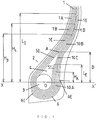
- FIG. 1 is a schematic view in cross section of a tire bead according to the invention.
- the example described is that of a tire of standard size 36 x 11.0 R 18 (standards of the Tire and Rim Association).
- the carcass reinforcement (1) is formed of five plies (1A to 1E) of radial textile cables.
- Radial cables are understood to mean cables making angles with the circumferential direction of the tire which may be in the range 90 ° ⁇ 10 °.
- three axially inner layers (1A, 1B, 1C) are wound in each bead (2) around a rod (3) (having in the case studied a circular cross section), going from the inside outside the tire P to form reversals (10A, 10B, 10C).
- the section of the rod (3) is surmounted radially on the outside by a profile or stuffing (4) of elastomeric mixture having substantially the shape of a triangle whose apex A, radially furthest from the axis of rotation of the tire, is situated at a distance D from the straight line XX ', on the one hand parallel to said axis of rotation and on the other hand passing through the geometric center O of the circle circumscribed to the cross section of the rod (3), a circle which is, in the case described, coincident with the section itself.
- the radial end of the axially inner strand (5I) of the tongue (5) composed of radial textile cables identical to the cables of the carcass plies (but which may be different), end located at a radial distance L I of 80 mm, relative to the straight line XX ', greater than the quantities H B and H C above, the three ends thus arranged radially above the vertex A being staggered between the said vertex and the point of the flank where the tire has a maximum axial width.
- the two carcass plies (1D) and (1E) called external cover axially outside the reversals (10A, 10B, 10C) of the carcass plies (1A) to (1C) interior.
- the sheets (1D) and (1E) are wound around the rod (3) on a portion or circular arc corresponding to an angle at the center of the circle circumscribed to the rod (3) at most equal to 180 °, so that the ends of these plies (1D) and (1E) are radially located below the reference line XX '.
- the tire bead (2) is completed by a reinforcement ply (6) or external tongue of radial textile cables, said ply allowing better distribution of the pressures between the tire and its service rim, as well as ensuring protection of the carcass plies against assembly attacks.
- the axially outer end (6E) of said tongue is slightly above the reference line XX '(2 mm), while its axially inner end (6I) is below said line.
- Such an architecture was tested on a dynamometric flywheel under conditions that penalize the endurance of the beads, conditions corresponding to a taxiway simulation (10160 kg, 4572 m, 46 km / h), followed by takeoff from 0 to 300 km / h, the pressure conditions being such that the deflection deflection of the tire under the 10,160 kg load is 52% ⁇ 2% of its height.
Abstract
Description
La présente invention concerne un pneumatique à armature de carcasse radiale destiné à porter de lourdes charges et gonflé à des pressions relativement fortes, et en particulier un pneumatique pour avions.The present invention relates to a tire with a radial carcass reinforcement intended to carry heavy loads and inflated to relatively high pressures, and in particular an aircraft tire.
Les armatures de carcasse radiales de tels pneumatiques comportent généralement plusieurs nappes de câbles textiles, qui sont ancrées dans chaque bourrelet à au moins une tringle et le plus souvent une seule tringle. Les éléments de renforcement de ces armatures sont enroulés autour de ladite tringle de l'intérieur à l'extérieur en formant des retournements dont les extrémités respectives sont radialement espacées par rapport à l'axe de rotation du pneumatique. Les conditions sévères sous lesquelles sont utilisés les pneumatiques pour avions sont telles que l'endurance des bourrelets est faible, en particulier au niveau des retournements de l'armature de carcasse.The radial carcass reinforcements of such tires generally comprise several plies of textile cables, which are anchored in each bead to at least one bead and most often only one bead. The reinforcing elements of these reinforcements are wound around said bead wire from the inside to the outside, forming reversals, the respective ends of which are radially spaced from the axis of rotation of the tire. The severe conditions under which aircraft tires are used are such that the endurance of the beads is low, in particular at the level of the reversals of the carcass reinforcement.
Une amélioration notable des performances est obtenue par la séparation des nappes de l'armature de carcasse en deux groupes. Le premier groupe comprend les nappes de l'armature de carcasse axialement intérieures dans la zone des bourrelets, ces nappes étant alors enroulées autour d'une tringle dans chaque bourrelet en allant de l'intérieur à l' extérieur du pneumatique. Le deuxième groupe est constitué d'au moins une nappe axialement extérieure dans la zone des bourrelets, nappe généralement enroulée autour de la tringle en allant de l'extérieur à l'intérieur du pneumatique.A significant improvement in performance is obtained by separating the plies of the carcass reinforcement in two groups. The first group comprises the plies of the axially inner carcass reinforcement in the region of the beads, these plies then being wound around a bead wire in each bead from the inside to the outside of the tire. The second group consists of at least one axially outer ply in the region of the beads, ply generally wound around the bead wire from the outside to the inside of the tire.
De telles dispositions sont connues et montrées par exemple dans le brevet US 4 244 414 (Fig. 2), ou encore le brevet US 5 215 445.Such arrangements are known and shown for example in US Pat. No. 4,244,414 (Fig. 2), or even US Patent 5,215,445.
L'endurance des bourrelets ainsi constitués peut être améliorée par la présence dans chaque bourrelet d'une nappe de renforcement supplémentaire enroulée autour de la tringle et formant ainsi un brin axialement extérieur et un brin axialement intérieur, ladite nappe de renforcement, nommée aussi languette intérieure, étant la nappe la plus proche du profilé caoutchouteux de remplissage ou bourrage, radialement au-dessus de la tringle d'ancrage. Une telle architecture est montrée dans le brevet US 5 285 835.The endurance of the beads thus formed can be improved by the presence in each bead of an additional reinforcing ply wound around the rod and thus forming an axially outer strand and an axially inner strand, said reinforcing ply, also called inner tongue. , being the sheet closest to the rubber filling or stuffing profile, radially above the anchor rod. Such an architecture is shown in US Patent 5,285,835.
L'endurance des bourrelets de pneumatiques pour avions se doit cependant d'être encore améliorée, en particulier lorsqu'ils subissent de fortes surcharges pouvant leur conférer des écrasement de l'ordre de 50% et plus de leur hauteur. La solution proposée par la présente invention réside dans la disposition précise des extrémités des portions retournées ou retournements des nappes de carcasse intérieures et des extrémités des brins de la languette intérieure par rapport à la position radiale de l'extrémité radialement supérieure du bourrage caoutchouteux situé au-dessus de la tringle d'ancrage.The endurance of tire beads for aircraft must however be further improved, in particular when they are subjected to heavy overloads which can give them crushing of the order of 50% and more of their height. The solution proposed by the present invention lies in the precise arrangement of the ends of the turned-over or turned-over portions of the inner carcass plies and of the ends of the strands of the inner tongue relative to the radial position of the radially upper end of the rubber stuffing located at the - above the anchor rod.
Conformément à l'invention, un pneumatique pour avion, gonflé à pression élevée, avec une bande de roulement, une armature de sommet et une armature de carcasse radiale comprenant au moins deux nappes axialement intérieures de câbles textiles, enroulées autour d'une tringle dans chaque bourrelet de l'intérieur à l'extérieur en formant des retournements et au moins une nappe axialement extérieure de câbles textiles superposée aux nappes intérieures sous l'armature de sommet et se séparant desdites nappes dans les bourrelets pour s'étendre le long des retournements dans lesdits bourrelets, ladite tringle étant radialement surmontée d'un bourrage de mélange caoutchouteux vulcanisé, de forme sensiblement triangulaire et dont le sommet radialement le plus éloigné de l'axe de rotation est à une distance D d'une droite, parallèle audit axe et passant par le centre géométrique du cercle circonscrit à la section transversale de la tringle d'ancrage, dite droite de référence, et comprenant aussi au moins une languette intérieure, enroulée autour de la tringle pour former un brin axialement intérieur et un brin axialement extérieur axialement adjacents au bourrage du dessus de tringle, caractérisé en ce que
- l'extrémité du brin axialement extérieur de la languette intérieure est située à une distance radiale LE de la droite de référence telle que LE soit comprise entre 0,40 D et 0,8O D ;
- l'extrémité du retournement de la nappe de carcasse intérieure disposée axialement la plus à l'intérieur est située à une distance HA de la droite de référence telle que HA soit comprise entre 0,15 D et 0,50 D, et en ce que,
- les extrémités respectivement du brin intérieur de la languette intérieure et des retournements des nappes de carcasse intérieures axialement les plus à l'extérieur sont situées à des distances radiales de la droite de référence supérieures à la distance D.
- the end of the axially outer strand of the inner tongue is located at a radial distance L E from the reference line such that L E is between 0.40 D and 0.8O D;
- the end of the upturn of the interior carcass ply axially innermost is located at a distance H A from the reference line such that H A is between 0.15 D and 0.50 D, and what,
- the ends respectively of the inner strand of the inner tongue and of the reversals of the axially outermost inner carcass plies are located at radial distances from the reference line greater than the distance D.
Préférentiellement, l'extrémité du brin intérieur de la languette intérieure est plus éloignée de la droite de référence que l'(les) extrémité(s) du (des) retournement (s) de la (des) nappe(s) de carcasse intérieure(s) axialement la (les) plus à l'extérieur.Preferably, the end of the inner strand of the inner tongue is further from the reference line than the end (s) of the reversal (s) of the inner carcass ply (s) (s) axially outermost.
De même, il est avantageux que les extrémités respectivement des brins de la languette intérieure et des nappes de carcasse intérieures soient radialement étagées, c'est-à-dire que chaque extrémité de nappe de renforcement soit située à une distance radiale de la droite de référence différente des distances radiales afférentes aux autres nappes.Similarly, it is advantageous that the ends respectively of the strands of the inner tongue and of the inner carcass plies are radially stepped, that is to say that each end of the reinforcing ply is located at a radial distance from the right of reference different from the radial distances relating to the other layers.
Le bourrelet de pneumatique sera avantageusement complété par la présence d'une nappe de renforcement additionnelle de câbles textiles ou languette extérieure, située autour de la tringle axialement et radialement le plus à l'extérieur, et dont l'extrémité du brin axialement extérieur est située à une distance de la droite XX' inférieure ou égale à ± 0,15 D.The tire bead will advantageously be completed by the presence of an additional reinforcement ply of textile cables or external tongue, situated around the bead axially and radially outermost, and the end of the axially outer strand of which is situated at a distance from line XX 'less than or equal to ± 0.15 D.
L'invention sera mieux comprise à l'aide de la description qui va suivre, faite en référence au dessin annexé et donnée à titre d'exemple non limitatif. Sur ce dessin, la figure 1 est une vue schématique en coupe transversale d'un bourrelet de pneumatique conforme à l'invention.The invention will be better understood with the aid of the description which follows, given with reference to the appended drawing and given by way of nonlimiting example. In this drawing, FIG. 1 is a schematic view in cross section of a tire bead according to the invention.
L'exemple décrit est celui d'un pneumatique de dimension normalisée 36 x 11.0 R 18 (normes de la Tire and Rim Association). L'armature de carcasse (1) est formée de cinq nappes (1A à 1E) de câbles textiles radiaux. Il faut entendre par câbles radiaux des câbles faisant avec la direction circonférentielle du pneumatique des angles pouvant être compris dans l'intervalle 90° ± 10°. Parmi ces cinq nappes, trois nappes (1A, 1B, 1C) axialement intérieures sont enroulées dans chaque bourrelet (2) autour d'une tringle (3) (ayant dans le cas étudié une section transversale circulaire), en allant de l'intérieur à l'extérieur du pneumatique P pour former des retournements (10A, 10B, 10C).The example described is that of a tire of standard size 36 x 11.0 R 18 (standards of the Tire and Rim Association). The carcass reinforcement (1) is formed of five plies (1A to 1E) of radial textile cables. Radial cables are understood to mean cables making angles with the circumferential direction of the tire which may be in the range 90 ° ± 10 °. Among these five layers, three axially inner layers (1A, 1B, 1C) are wound in each bead (2) around a rod (3) (having in the case studied a circular cross section), going from the inside outside the tire P to form reversals (10A, 10B, 10C).
La section de la tringle (3) est surmontée radialement à l'extérieur par un profilé ou bourrage (4) de mélange élastomérique ayant sensiblement la forme d'un triangle dont le sommet A, radialement le plus éloigné de l'axe de rotation du pneumatique, est situé à une distance D de la droite XX', d'une part parallèle audit axe de rotation et d'autre part passant par le centre géométrique O du cercle circonscrit à la section transversale de la tringle (3), cercle qui est, dans le cas décrit, confondu avec la section elle-même.The section of the rod (3) is surmounted radially on the outside by a profile or stuffing (4) of elastomeric mixture having substantially the shape of a triangle whose apex A, radially furthest from the axis of rotation of the tire, is situated at a distance D from the straight line XX ', on the one hand parallel to said axis of rotation and on the other hand passing through the geometric center O of the circle circumscribed to the cross section of the rod (3), a circle which is, in the case described, coincident with the section itself.
Le retournement (10A) de la nappe de carcasse intérieure (1A), axialement la plus à l'intérieur, a son extrémité distante radialement de la droite XX' de la quantité HA, qui est égale, dans le cas étudié, à 12 mm, soit 0,33 fois la distance D, égale à 36 mm. Quant aux extrémités, respectivement des nappes intérieures (10B) et (10C), elles sont radialement situées au-dessus du sommet A du bourrage (4) à des distances respectivement HB et HC de 55 mm et 68 mm.The inversion (10A) of the inner carcass ply (1A), axially innermost, at its end radially distant from the line XX 'by the quantity H A , which is equal, in the case studied, to 12 mm, i.e. 0.33 times the distance D, equal to 36 mm. As for the ends, respectively of the inner plies (10B) and (10C), they are radially situated above the apex A of the packing (4) at distances H B and H C of 55 mm and 68 mm respectively.
Il en est de même de l'extrémité radiale du brin axialement intérieur (5I) de la languette (5), composée de câbles textiles radiaux identiques aux câbles des nappes de carcasse (mais qui peuvent être différents), extrémité située à une distance radiale LI de 80 mm, par rapport à la droite XX', supérieure aux quantités HB et HC ci-dessus, les trois extrémités ainsi disposées radialement au-dessus du sommet A étant étagées entre ledit sommet et le point du flanc où le pneumatique possède une largeur axiale maximale. Quant à l'extrémité radiale du brin axialement extérieur (5E) de la languette intérieure (5), elle est séparée de la droite XX' par la distance radiale LE, égale à 21 mm et, dans le cas de la dimension de pneumatique considéré, supérieure à la distance HA, puisqu'égale à 0,58 D.It is the same for the radial end of the axially inner strand (5I) of the tongue (5), composed of radial textile cables identical to the cables of the carcass plies (but which may be different), end located at a radial distance L I of 80 mm, relative to the straight line XX ', greater than the quantities H B and H C above, the three ends thus arranged radially above the vertex A being staggered between the said vertex and the point of the flank where the tire has a maximum axial width. As for the radial end of the axially outer strand (5E) of the inner tab (5), it is separated from the straight line XX 'by the radial distance L E , equal to 21 mm and, in the case of the tire dimension considered, greater than the distance H A , since it equals 0.58 D.
Les deux nappes de carcasse (1D) et (1E) dites extérieures recouvrent axialement à l'extérieur les retournements (10A, 10B, 10C) des nappes de carcasse (1A) à (1C) intérieures. Les nappes (1D) et (1E) sont enroulées autour de la tringle (3) sur une portion ou arc circulaire correspondant à un angle au centre du cercle circonscrit à la tringle (3) au plus égal à 180°, de sorte que les extrémités de ces nappes (1D) et (1E) soient radialement situées au-dessous de la droite XX' de référence.The two carcass plies (1D) and (1E) called external cover axially outside the reversals (10A, 10B, 10C) of the carcass plies (1A) to (1C) interior. The sheets (1D) and (1E) are wound around the rod (3) on a portion or circular arc corresponding to an angle at the center of the circle circumscribed to the rod (3) at most equal to 180 °, so that the ends of these plies (1D) and (1E) are radially located below the reference line XX '.
Le bourrelet (2) de pneumatique est complété par une nappe de renforcement (6) ou languette extérieure de câbles textiles radiaux, ladite nappe permettant de mieux répartir les pressions entre le pneumatique et sa jante de service, ainsi que d'assurer une protection des nappes de carcasse contre les agressions de montage.The tire bead (2) is completed by a reinforcement ply (6) or external tongue of radial textile cables, said ply allowing better distribution of the pressures between the tire and its service rim, as well as ensuring protection of the carcass plies against assembly attacks.
L'extrémité axialement extérieure (6E) de ladite languette est légèrement au-dessus de la droite XX' de référence (2 mm), alors que son extrémité axialement intérieure (6I) est au-dessous de ladite droite.The axially outer end (6E) of said tongue is slightly above the reference line XX '(2 mm), while its axially inner end (6I) is below said line.
Une telle architecture a été testée sur volant dynamométrique dans des conditions pénalisantes pour l'endurance des bourrelets, conditions correspondantes à une simulation de roulage sur "taxiway" ( 10160 kg, 4572 m, 46 km/h), suivi d'un décollage de 0 à 300 km/h, les conditions de pression étant telles que la flèche d'écrasement du pneumatique sous les 10160 kg de charge soit de 52% ± 2% de sa hauteur.Such an architecture was tested on a dynamometric flywheel under conditions that penalize the endurance of the beads, conditions corresponding to a taxiway simulation (10160 kg, 4572 m, 46 km / h), followed by takeoff from 0 to 300 km / h, the pressure conditions being such that the deflection deflection of the tire under the 10,160 kg load is 52% ± 2% of its height.
La comparaison avec un pneumatique de même dimension, comprenant le même nombre de nappes de carcasse et deux languettes intérieure et extérieure, la nappe de carcasse intérieure la plus à l'intérieur ayant un retournement dont l'extrémité est située au-dessus du sommet A, et le brin extérieur de la languette intérieure ayant son extrémité au-dessous dudit sommet, met en évidence de manière nette et inattendue l'amélioration de l'endurance des bourrelets, puisque les enveloppes de l'invention, dans les conditions ci-dessus, ont réalisé un nombre de cycles "taxiway"-décollage supérieurs de 35% en moyenne.Comparison with a tire of the same dimension, comprising the same number of carcass plies and two interior and exterior tabs, the innermost interior carcass ply having a reversal, the end of which is situated above the apex A , and the outer strand of the inner tongue having its end below said apex, clearly and unexpectedly highlights the improvement in the endurance of the beads, since the envelopes of the invention, under the above conditions , performed an average of 35% higher taxiway-takeoff cycles.
Claims (4)
Applications Claiming Priority (2)
| Application Number | Priority Date | Filing Date | Title |
|---|---|---|---|
| FR9509407A FR2737442A1 (en) | 1995-07-31 | 1995-07-31 | TIRE WITH REINFORCED SADDLES |
| FR9509407 | 1995-07-31 |
Publications (2)
| Publication Number | Publication Date |
|---|---|
| EP0756950A1 true EP0756950A1 (en) | 1997-02-05 |
| EP0756950B1 EP0756950B1 (en) | 2000-02-23 |
Family
ID=9481642
Family Applications (1)
| Application Number | Title | Priority Date | Filing Date |
|---|---|---|---|
| EP96110661A Expired - Lifetime EP0756950B1 (en) | 1995-07-31 | 1996-07-02 | Tyre with reinforced beads |
Country Status (6)
| Country | Link |
|---|---|
| US (1) | US5769982A (en) |
| EP (1) | EP0756950B1 (en) |
| JP (1) | JP3784891B2 (en) |
| CA (1) | CA2182308C (en) |
| DE (1) | DE69606743T2 (en) |
| FR (1) | FR2737442A1 (en) |
Cited By (4)
| Publication number | Priority date | Publication date | Assignee | Title |
|---|---|---|---|---|
| WO2009092648A1 (en) * | 2008-01-24 | 2009-07-30 | Societe De Technologie Michelin | Carcass reinforcement for airplane tyre |
| WO2012003203A1 (en) * | 2010-06-30 | 2012-01-05 | Bridgestone Americas Tire Operations, Llc | Tire having staggered turn-ups |
| US8517072B2 (en) | 2010-02-04 | 2013-08-27 | Bridgestone Americas Tire Operations, Llc | Tire having gum strip and chafer |
| WO2017187032A1 (en) | 2016-04-25 | 2017-11-02 | Compagnie Generale Des Etablissements Michelin | Aeroplane tyre having a casing reinforcement with improved endurance |
Families Citing this family (7)
| Publication number | Priority date | Publication date | Assignee | Title |
|---|---|---|---|---|
| FR2821794B1 (en) * | 2001-03-09 | 2004-02-27 | Michelin Soc Tech | CARCASS REINFORCEMENT FOR AIRCRAFT TIRES |
| US6648041B2 (en) | 2001-08-31 | 2003-11-18 | The Goodyear Tire & Rubber Company | Aircraft tire with improved bead structure |
| US6632239B2 (en) * | 2001-10-02 | 2003-10-14 | Spiration, Inc. | Constriction device including reinforced suture holes |
| US20050274444A1 (en) * | 2003-02-25 | 2005-12-15 | Kiyoshi Ueyoko | Aircraft tire with improved bead structure |
| US20060068866A1 (en) * | 2004-09-13 | 2006-03-30 | Pokertek, Inc. | Electronic card table and method |
| US8151849B2 (en) | 2008-06-12 | 2012-04-10 | The Goodyear Tire & Rubber Company | Radial aircraft tire with flipper reinforcement |
| KR101029032B1 (en) * | 2008-10-22 | 2011-04-15 | 금호타이어 주식회사 | Pneumatic tir |
Citations (4)
| Publication number | Priority date | Publication date | Assignee | Title |
|---|---|---|---|---|
| BE657324A (en) * | 1963-12-20 | 1965-06-18 | ||
| FR2669275A1 (en) * | 1990-11-21 | 1992-05-22 | Sumitomo Rubber Ind | Tyre for high speed and heavy loads, especially for aircraft |
| EP0595653A1 (en) * | 1992-10-30 | 1994-05-04 | Sumitomo Rubber Industries Limited | Pneumatic tyre |
| EP0599575A1 (en) * | 1992-11-24 | 1994-06-01 | Bridgestone Corporation | Airplane radial tire |
Family Cites Families (13)
| Publication number | Priority date | Publication date | Assignee | Title |
|---|---|---|---|---|
| US3245454A (en) * | 1964-04-23 | 1966-04-12 | Goodyear Tire & Rubber | Tire |
| FR1600345A (en) * | 1968-12-31 | 1970-07-20 | ||
| US3722567A (en) * | 1970-12-15 | 1973-03-27 | Pneumatiques Caoutchouc Mfg | Radial-ply pneumatic tire |
| JPS5486102A (en) * | 1977-12-19 | 1979-07-09 | Toyo Tire & Rubber Co Ltd | Radial tire for heavy loading |
| US5285835A (en) * | 1988-09-06 | 1994-02-15 | Sumitomo Rubber Industries, Ltd. | High speed radial tire with durable bead part |
| JP2758649B2 (en) * | 1989-06-15 | 1998-05-28 | 株式会社ブリヂストン | Radial tire for aircraft |
| JP2793672B2 (en) * | 1989-12-28 | 1998-09-03 | 住友ゴム工業株式会社 | High speed heavy duty tire |
| US5522443A (en) * | 1990-03-16 | 1996-06-04 | Sumitomo Rubber Industries, Ltd. | High speed heavy duty tire and rim assembly whose tire includes a buffer layer in each bead portion |
| JP3005042B2 (en) * | 1990-11-21 | 2000-01-31 | 住友ゴム工業株式会社 | High speed heavy duty tire |
| FR2671517A1 (en) * | 1991-01-14 | 1992-07-17 | Michelin & Cie | TIRE FOR HEAVY LOADS AND HIGH PRESSURE INFLATORS. |
| US5215445A (en) * | 1992-10-28 | 1993-06-01 | Chen Chia Sing | Handy vacuum pump and heat sealer combination device |
| JP2644953B2 (en) * | 1992-11-05 | 1997-08-25 | 住友ゴム工業株式会社 | Pneumatic tire |
| JP3081732B2 (en) * | 1993-07-02 | 2000-08-28 | 住友ゴム工業株式会社 | Radial tire for high speed heavy load |
-
1995
- 1995-07-31 FR FR9509407A patent/FR2737442A1/en active Pending
-
1996
- 1996-07-02 EP EP96110661A patent/EP0756950B1/en not_active Expired - Lifetime
- 1996-07-02 DE DE69606743T patent/DE69606743T2/en not_active Expired - Lifetime
- 1996-07-12 US US08/678,202 patent/US5769982A/en not_active Expired - Lifetime
- 1996-07-29 CA CA002182308A patent/CA2182308C/en not_active Expired - Fee Related
- 1996-07-30 JP JP20038496A patent/JP3784891B2/en not_active Expired - Fee Related
Patent Citations (4)
| Publication number | Priority date | Publication date | Assignee | Title |
|---|---|---|---|---|
| BE657324A (en) * | 1963-12-20 | 1965-06-18 | ||
| FR2669275A1 (en) * | 1990-11-21 | 1992-05-22 | Sumitomo Rubber Ind | Tyre for high speed and heavy loads, especially for aircraft |
| EP0595653A1 (en) * | 1992-10-30 | 1994-05-04 | Sumitomo Rubber Industries Limited | Pneumatic tyre |
| EP0599575A1 (en) * | 1992-11-24 | 1994-06-01 | Bridgestone Corporation | Airplane radial tire |
Cited By (10)
| Publication number | Priority date | Publication date | Assignee | Title |
|---|---|---|---|---|
| WO2009092648A1 (en) * | 2008-01-24 | 2009-07-30 | Societe De Technologie Michelin | Carcass reinforcement for airplane tyre |
| FR2926750A1 (en) * | 2008-01-24 | 2009-07-31 | Michelin Soc Tech | CARCASS FRAME FOR AIRCRAFT TIRE. |
| US8955569B2 (en) | 2008-01-24 | 2015-02-17 | Michelin Recherche Et Technique S.A. | Carcass reinforcement for airplane tire |
| US8413700B2 (en) | 2010-02-04 | 2013-04-09 | Bridgestone Americas Tire Operations, Llc | Tire having staggered turn-ups |
| US8517072B2 (en) | 2010-02-04 | 2013-08-27 | Bridgestone Americas Tire Operations, Llc | Tire having gum strip and chafer |
| US9440499B2 (en) | 2010-02-04 | 2016-09-13 | Bridgestone Americas Tire Operations, Llc | Tire having gum strip and chafer |
| WO2012003203A1 (en) * | 2010-06-30 | 2012-01-05 | Bridgestone Americas Tire Operations, Llc | Tire having staggered turn-ups |
| RU2584409C2 (en) * | 2010-06-30 | 2016-05-20 | БРИДЖСТОУН ЭМЕРИКАС ТАЙР ОПЕРЕЙШНС, ЭлЭлСи | Tyre (versions) |
| WO2017187032A1 (en) | 2016-04-25 | 2017-11-02 | Compagnie Generale Des Etablissements Michelin | Aeroplane tyre having a casing reinforcement with improved endurance |
| US10960709B2 (en) | 2016-04-25 | 2021-03-30 | Compagnie Generale Des Etablissements Michelin | Airplane tire having a casing reinforcement with improved endurance |
Also Published As
| Publication number | Publication date |
|---|---|
| EP0756950B1 (en) | 2000-02-23 |
| DE69606743T2 (en) | 2000-06-15 |
| JP3784891B2 (en) | 2006-06-14 |
| US5769982A (en) | 1998-06-23 |
| CA2182308A1 (en) | 1997-02-01 |
| CA2182308C (en) | 2006-09-12 |
| JPH09118113A (en) | 1997-05-06 |
| FR2737442A1 (en) | 1997-02-07 |
| DE69606743D1 (en) | 2000-03-30 |
Similar Documents
| Publication | Publication Date | Title |
|---|---|---|
| EP1084047B1 (en) | Radial tyre reinforced tyre bead | |
| EP1064159B1 (en) | Radial tyre reinforced bead | |
| EP3484726B1 (en) | Tyre with a reduced-weight bead region | |
| EP0756950B1 (en) | Tyre with reinforced beads | |
| WO2017191421A1 (en) | Tyre with a reduced-weight bead region | |
| WO1999034989A1 (en) | Tyre bead with circumferential reinforcing elements | |
| EP1077815B1 (en) | Radial tyre breaker ply reinforcement | |
| WO1999058352A1 (en) | Tyre with laced breaker ply reinforcement | |
| EP1047566A1 (en) | Tyre bead with circumferential reinforcing elements | |
| EP3484728B1 (en) | Tyre with a reduced-weight bead region | |
| EP1307349B1 (en) | Tyre with improved structural sidewalls | |
| EP1047567B1 (en) | Tyre bead with reinforcing circumferential elements | |
| EP0724973B1 (en) | Tyre bead | |
| EP1077814B1 (en) | Tyre breaker ply reinforcement | |
| EP1011992A1 (en) | Top reinforcement for tyre | |
| WO2017191422A1 (en) | Tyre with a reduced-weight bead region | |
| EP1185426A1 (en) | Coreless bead for tyre | |
| WO2017174904A1 (en) | Tyre carcass reinforcement for a two-wheeled vehicle | |
| WO2020094951A1 (en) | Tyre having a reduced-weight bead region | |
| EP3877201A1 (en) | Tyre having a reduced weight bead region |
Legal Events
| Date | Code | Title | Description |
|---|---|---|---|
| PUAI | Public reference made under article 153(3) epc to a published international application that has entered the european phase |
Free format text: ORIGINAL CODE: 0009012 |
|
| AK | Designated contracting states |
Kind code of ref document: A1 Designated state(s): BE DE FR GB IT LU |
|
| 17P | Request for examination filed |
Effective date: 19970805 |
|
| GRAG | Despatch of communication of intention to grant |
Free format text: ORIGINAL CODE: EPIDOS AGRA |
|
| 17Q | First examination report despatched |
Effective date: 19990420 |
|
| GRAG | Despatch of communication of intention to grant |
Free format text: ORIGINAL CODE: EPIDOS AGRA |
|
| GRAH | Despatch of communication of intention to grant a patent |
Free format text: ORIGINAL CODE: EPIDOS IGRA |
|
| GRAH | Despatch of communication of intention to grant a patent |
Free format text: ORIGINAL CODE: EPIDOS IGRA |
|
| GRAA | (expected) grant |
Free format text: ORIGINAL CODE: 0009210 |
|
| AK | Designated contracting states |
Kind code of ref document: B1 Designated state(s): BE DE FR GB IT LU |
|
| REF | Corresponds to: |
Ref document number: 69606743 Country of ref document: DE Date of ref document: 20000330 |
|
| ITF | It: translation for a ep patent filed |
Owner name: JACOBACCI & PERANI S.P.A. |
|
| GBT | Gb: translation of ep patent filed (gb section 77(6)(a)/1977) |
Effective date: 20000515 |
|
| PG25 | Lapsed in a contracting state [announced via postgrant information from national office to epo] |
Ref country code: LU Free format text: LAPSE BECAUSE OF NON-PAYMENT OF DUE FEES Effective date: 20000702 |
|
| EN | Fr: translation not filed | ||
| PG25 | Lapsed in a contracting state [announced via postgrant information from national office to epo] |
Ref country code: FR Free format text: LAPSE BECAUSE OF FAILURE TO SUBMIT A TRANSLATION OF THE DESCRIPTION OR TO PAY THE FEE WITHIN THE PRESCRIBED TIME-LIMIT Effective date: 20000721 |
|
| PG25 | Lapsed in a contracting state [announced via postgrant information from national office to epo] |
Ref country code: BE Free format text: LAPSE BECAUSE OF NON-PAYMENT OF DUE FEES Effective date: 20000731 |
|
| EN4 | Fr: notification of non filing translation in an earlier bopi is erroneous | ||
| PLBE | No opposition filed within time limit |
Free format text: ORIGINAL CODE: 0009261 |
|
| STAA | Information on the status of an ep patent application or granted ep patent |
Free format text: STATUS: NO OPPOSITION FILED WITHIN TIME LIMIT |
|
| BERE | Be: lapsed |
Owner name: CIE GENERALE DES ETS MICHELIN - MICHELIN & CIE Effective date: 20000731 |
|
| 26N | No opposition filed | ||
| REG | Reference to a national code |
Ref country code: GB Ref legal event code: IF02 |
|
| PGFP | Annual fee paid to national office [announced via postgrant information from national office to epo] |
Ref country code: GB Payment date: 20060720 Year of fee payment: 11 |
|
| GBPC | Gb: european patent ceased through non-payment of renewal fee |
Effective date: 20070702 |
|
| PG25 | Lapsed in a contracting state [announced via postgrant information from national office to epo] |
Ref country code: GB Free format text: LAPSE BECAUSE OF NON-PAYMENT OF DUE FEES Effective date: 20070702 |
|
| PGFP | Annual fee paid to national office [announced via postgrant information from national office to epo] |
Ref country code: DE Payment date: 20140721 Year of fee payment: 19 |
|
| PGFP | Annual fee paid to national office [announced via postgrant information from national office to epo] |
Ref country code: FR Payment date: 20140721 Year of fee payment: 19 |
|
| PGFP | Annual fee paid to national office [announced via postgrant information from national office to epo] |
Ref country code: IT Payment date: 20140729 Year of fee payment: 19 |
|
| REG | Reference to a national code |
Ref country code: DE Ref legal event code: R119 Ref document number: 69606743 Country of ref document: DE |
|
| PG25 | Lapsed in a contracting state [announced via postgrant information from national office to epo] |
Ref country code: IT Free format text: LAPSE BECAUSE OF NON-PAYMENT OF DUE FEES Effective date: 20150702 Ref country code: DE Free format text: LAPSE BECAUSE OF NON-PAYMENT OF DUE FEES Effective date: 20160202 |
|
| REG | Reference to a national code |
Ref country code: FR Ref legal event code: ST Effective date: 20160331 |
|
| PG25 | Lapsed in a contracting state [announced via postgrant information from national office to epo] |
Ref country code: FR Free format text: LAPSE BECAUSE OF FAILURE TO SUBMIT A TRANSLATION OF THE DESCRIPTION OR TO PAY THE FEE WITHIN THE PRESCRIBED TIME-LIMIT Effective date: 20150731 |