EP0756814B1 - Brushmower housing - Google Patents
Brushmower housing Download PDFInfo
- Publication number
- EP0756814B1 EP0756814B1 EP19960420263 EP96420263A EP0756814B1 EP 0756814 B1 EP0756814 B1 EP 0756814B1 EP 19960420263 EP19960420263 EP 19960420263 EP 96420263 A EP96420263 A EP 96420263A EP 0756814 B1 EP0756814 B1 EP 0756814B1
- Authority
- EP
- European Patent Office
- Prior art keywords
- housing
- cutting means
- towards
- plane
- strip
- Prior art date
- Legal status (The legal status is an assumption and is not a legal conclusion. Google has not performed a legal analysis and makes no representation as to the accuracy of the status listed.)
- Expired - Lifetime
Links
Images

Classifications
-
- A—HUMAN NECESSITIES
- A01—AGRICULTURE; FORESTRY; ANIMAL HUSBANDRY; HUNTING; TRAPPING; FISHING
- A01D—HARVESTING; MOWING
- A01D34/00—Mowers; Mowing apparatus of harvesters
- A01D34/01—Mowers; Mowing apparatus of harvesters characterised by features relating to the type of cutting apparatus
- A01D34/412—Mowers; Mowing apparatus of harvesters characterised by features relating to the type of cutting apparatus having rotating cutters
- A01D34/63—Mowers; Mowing apparatus of harvesters characterised by features relating to the type of cutting apparatus having rotating cutters having cutters rotating about a vertical axis
- A01D34/81—Casings; Housings
-
- A—HUMAN NECESSITIES
- A01—AGRICULTURE; FORESTRY; ANIMAL HUSBANDRY; HUNTING; TRAPPING; FISHING
- A01D—HARVESTING; MOWING
- A01D57/00—Delivering mechanisms for harvesters or mowers
- A01D57/01—Devices for leading crops to the mowing apparatus
-
- A—HUMAN NECESSITIES
- A01—AGRICULTURE; FORESTRY; ANIMAL HUSBANDRY; HUNTING; TRAPPING; FISHING
- A01D—HARVESTING; MOWING
- A01D2101/00—Lawn-mowers
Definitions
- the invention relates to brushcutters comprising cutting means rotary, composed of a blade or a disc fitted with knives, these means being calibrated to the end of a vertical drive shaft and describing a horizontal path under a casing protective.
- These machines which are intended to cut plants of all kinds, of all size and having rods of variable dimensions, are generally equipped with an open casing forward.
- the housing is sled or cylindrical with a vertical axis coaxial with the axis of rotation of the cutting means, it has, on its front part, a rectangular opening allowing the cutting means to cut the base of the plant stems.
- the cut plants In operation, and due to the presence of the side walls of the housing, the cut plants have no other option than to pass through the edges side, which causes more or less quickly jams that can block the cutting means and in any case, disrupting their function.
- the object of the present invention is to provide a casing which remedies these disadvantages and improves not only the sectioning of plants but also their extraction out of the housing.
- the deflecting wall is constituted by a semi-circular strip, frustoconical and diverging upwards, which fixed on the part front of the housing, extends, in the direction of rotation of the cutting means, from a point disposed in front of the transverse median plane of the casing up to the lateral ejection orifice.
- the part upper part of its frusto-conical strip extending above the circular trajectory of the cutting means, not only promotes cutting of plant stems by bending them forward, but also, by its frustoconical semicircular shape and thanks to the energy communicated to the rods by the cutting means, deflects these rods laterally, thus avoiding that they accumulate under the casing and cause jams.
- the front strip is extended, towards the rear and above a ejection opening made on one side of the housing, by a sloping deflector running rising from the housing outwards.
- the stems of the cut plants, along the front strip under the push cutting means, are brought by these means against the deflector which, by exerting on pressure at a higher level from the ground forces them to lie down laterally outwards and thus avoid any jamming phenomenon.
- the brushcutter is provided with means cutting comprising a blade 2, wedged in the middle on a motor shaft 3 mounted free in rotation in a bearing 4, integral with a casing 5 carried by a chassis 6.
- the motor shaft is driven, for example by a belt transmission 7, by a motor unit ensuring also the drive of two rear drive wheels 9.
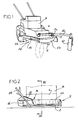
- the chassis is equipped, as shown in Figure 1, at least one and possibly two arms 10, carrying a crazy wheel 12.
- the casing 5 is of the cylindrical type with a vertical axis and therefore comprises a flat and horizontal upper wall 5a and a cylindrical wall 5b.
- the Figure 3 shows that the wall 5b is lower on the front of the device, since it comes above of the path of the blade 2.
- the casing 5 comprises, in its front part, a semi-circular strip and frustoconical 13 which diverges upwards.
- This semi circular headband does extends only over part of the periphery of the casing and, more precisely, and in the direction of rotation of the cutting means, represented by arrow 14 in FIG. 4, from a point A, disposed in front of the transverse median plane P1 of the casing 5, up to a point B, disposed beyond of the longitudinal median plane P2 of the casing and constitute the beginning of the ejection orifice 16 lateral.
- This strip is substantially coaxial with the axis of rotation of the blade 2.
- the radius RB of the lower edge of the strip 13 is smaller than the radius RT of the circular path of the blade 2, while the edge upper of this strip has a radius RH which is larger than that RT above.
- this headband protects cutting means against all contact with non-flexible vertical bodies and, in particular, with the trees.
- This strip 13 is extended towards the rear by a sloping deflector 15, which disposed above the ejection orifice 16, goes up from the casing towards the outside.
- FIG. 4 shows that the internal longitudinal edge 15a of the deflector 15 is connects to the upper wall 5a of the casing by a straight line which intersects the trajectory circular 2a of the blade 2 and which extends on either side of the transverse median plane P1.
- this intersection 15a forms, with the longitudinal axis of the brushcutter, materialized at Figure 4 by the trace of the plane P2, an angle a which is acute and which diverges towards the back.
- the invention considerably improves the cutting conditions and the ejection conditions of the plants, which provides better working conditions and better yields.
Description
L'invention est relative aux débroussailleuses comportant des moyens de coupe rotatifs, composés d'une lame ou d'un disque équipé de couteaux, ces moyens étant calés à l'extrémité d'un arbre moteur vertical et décrivant une trajectoire horizontale sous un carter protecteur.The invention relates to brushcutters comprising cutting means rotary, composed of a blade or a disc fitted with knives, these means being calibrated to the end of a vertical drive shaft and describing a horizontal path under a casing protective.
Ces machines, qui sont destinées à couper des végétaux de toute nature, de toute taille et ayant des tiges de dimensions variables, sont en général dotées d'un carter ouvert vers l'avant. Que le carter soit de type traíneau ou cylindrique à axe vertical coaxial à l'axe de rotation des moyens de coupe, il comporte, sur sa partie avant, une ouverture rectangulaire permettant aux moyens de coupe de sectionner la base des tiges des végétaux.These machines, which are intended to cut plants of all kinds, of all size and having rods of variable dimensions, are generally equipped with an open casing forward. Whether the housing is sled or cylindrical with a vertical axis coaxial with the axis of rotation of the cutting means, it has, on its front part, a rectangular opening allowing the cutting means to cut the base of the plant stems.
En fonctionnement, et en raison de la présence des parois latérales du carter, les végétaux coupés n'ont pas d'autre possibilité que de s'évacuer en passant sur les bords latéraux, ce qui provoque plus ou moins rapidement des bourrages pouvant bloquer les moyens de coupe et en tous cas, perturbant leur fonction.In operation, and due to the presence of the side walls of the housing, the cut plants have no other option than to pass through the edges side, which causes more or less quickly jams that can block the cutting means and in any case, disrupting their function.
On connaít par US-A-2872770 et par FR-A-2685993 des dispositifs de débroussaillage comportant, une paroi antérieure déflectrice qui, disposée au dessus de la trajectoire des moyens de coupe, va en s'élevant vers l'avant et vers le haut en allant d'un point bas, disposé dans la zone d'action des moyens de coupe, jusqu'à un point haut, disposé en avant de cette trajectoire.We know from US-A-2872770 and from FR-A-2685993 brushcutting comprising a deflecting front wall which, disposed above the trajectory of the cutting means, going upwards and upwards going from one low point, arranged in the area of action of the cutting means, up to a high point, arranged ahead of this trajectory.
De telles parois courbent les végétaux vers l'avant, avant leur sectionnement, mais n'éliminent pas les bourrages.Such walls curve the plants forward, before they are cut, but do not clear jams.
La présente invention a pour but de fournir un carter qui remédie à ces inconvénients et améliore, non seulement, le sectionnement des végétaux mais aussi leur extraction hors du carter.The object of the present invention is to provide a casing which remedies these disadvantages and improves not only the sectioning of plants but also their extraction out of the housing.
A cet effet, dans le carter selon l'invention, la paroi déflectrice est constituée par un bandeau semi-circulaire, tronconique et divergeant vers le haut, qui fixé sur la partie avant du carter, s'étend, dans le sens de rotation des moyens de coupe, depuis un point disposé en avant du plan médian transversal du carter jusqu'à l'orifice d'éjection latérale.To this end, in the casing according to the invention, the deflecting wall is constituted by a semi-circular strip, frustoconical and diverging upwards, which fixed on the part front of the housing, extends, in the direction of rotation of the cutting means, from a point disposed in front of the transverse median plane of the casing up to the lateral ejection orifice.
Grâce à cet agencement, lors de l'avancement de la débroussailleuse, la partie supérieure de son bandeau tronconique, s'étendant au-dessus de la trajectoire circulaire des moyens de coupe, non seulement favorise la coupe des tiges des végétaux en les courbant vers l'avant, mais aussi, par sa forme semi-circulaire tronconique et grâce à l'énergie communiquée aux tiges par les moyens de coupe, dévie ces tiges latéralement en évitant ainsi qu'elles s'accumulent sous le carter et provoquent des bourrages..Thanks to this arrangement, during the advancement of the brushcutter, the part upper part of its frusto-conical strip, extending above the circular trajectory of the cutting means, not only promotes cutting of plant stems by bending them forward, but also, by its frustoconical semicircular shape and thanks to the energy communicated to the rods by the cutting means, deflects these rods laterally, thus avoiding that they accumulate under the casing and cause jams.
Avantageusement, le bandeau avant est prolongé, vers l'arrière et au-dessus d'un orifice d'éjection ménagé sur l'un des côtés du carter, par un déflecteur pentu allant en s'élevant depuis le carter vers l'extérieur. Advantageously, the front strip is extended, towards the rear and above a ejection opening made on one side of the housing, by a sloping deflector running rising from the housing outwards.
Ainsi, les tiges des végétaux coupés, longeant le bandeau avant sous la poussée des moyens de coupe, sont amenées par ces moyens contre le déflecteur qui, en exerçant sur eux, une pression à un niveau plus élevé par rapport au sol, les obligent à se coucher latéralement vers l'extérieur et évitent ainsi tout phénomène de bourrage.Thus, the stems of the cut plants, along the front strip under the push cutting means, are brought by these means against the deflector which, by exerting on pressure at a higher level from the ground forces them to lie down laterally outwards and thus avoid any jamming phenomenon.
D'autres caractéristiques et avantages ressortiront de la description qui suit en
référence au dessin schématique annexé représentant, à titre d'exemple, une forme
d'exécution d'une débroussailleuse équipée du carter selon l'invention.
Dans la forme d'exécution représentée, la débroussailleuse est dotée de moyens
de coupe comprenant une lame 2, calée en son milieu sur un arbre moteur 3 monté libre en
rotation dans un palier 4, solidaire d'un carter 5 porté par un châssis 6. L'arbre moteur est
entraíné, par exemple par une transmission par courroie 7, par un groupe moteur assurant
également l'entraínement de deux roues motrices arrières 9. Sur l'avant, le châssis est équipé,
comme montré à la figure 1, d'au moins un et éventuellement de deux bras 10, porteurs d'une
roue folle 12.In the embodiment shown, the brushcutter is provided with means
cutting comprising a
Comme le montre la figure 4, le carter 5 est du type cylindrique à axe vertical et
comporte donc une paroi supérieure plane et horizontale 5a et une paroi cylindrique 5b. La
figure 3 montre que la paroi 5b est moins haute sur l'avant de l'appareil, puisqu'elle vient au-dessus
de la trajectoire de la lame 2.As shown in FIG. 4, the
Selon l'invention, le carter 5 comporte, dans sa partie avant, un bandeau semi-circulaire
et tronconique 13 qui va en divergeant vers le haut. Ce bandeau semi circulaire ne
s'étend que sur une partie de la périphérie du carter et, plus précisément, et dans le sens de
rotation des moyens de coupe, représentée par la flèche 14 à la figurer 4, depuis un point A,
disposé en avant du plan médian transversal P1 du carter 5, jusqu'à un point B, disposé au-delà
du plan médian longitudinal P2 du carter et constituent le début de l'orifice 16 d'éjection
latérale. Ce bandeau est sensiblement coaxial à l'axe de rotation de la lame 2.According to the invention, the
Comme le montre la figure 3, le rayon RB du bord inférieur du bandeau 13 est
plus petit que le rayon RT de la trajectoire circulaire de la lame 2, tandis que le bord
supérieur de ce bandeau a un rayon RH qui est plus grand que celui RT précité.As shown in FIG. 3, the radius RB of the lower edge of the
Indépendamment des avantages exposés plus loin, ce bandeau protège les moyens de coupe contre tous contacts avec des corps verticaux non flexibles et, en particulier, avec les arbres.Regardless of the advantages explained below, this headband protects cutting means against all contact with non-flexible vertical bodies and, in particular, with the trees.
Ce bandeau 13 se prolonge vers l'arrière par un déflecteur pentu 15, qui disposé
au-dessus de l'orifice d'éjection 16, va en s'élevant depuis le carter vers l'extérieur. This
La figure 4 montre que le bord longitudinal interne 15a du déflecteur 15 se
raccorde à la paroi supérieure 5a du carter par une ligne droite qui sécante la trajectoire
circulaire 2a de la lame 2 et qui s'étend de part et d'autre du plan médian transversal P1. De
plus, cette intersection 15a forme, avec l'axe longitudinal de la débroussailleuse, matérialisé à
la figure 4 par la trace du plan P2, un angle a qui est aigu et qui va en divergeant vers
l'arrière.FIG. 4 shows that the internal
Grâce à cet agencement, lorsque la débroussailleuse est déplacée dans le sens de
la flèche 17 de figure 3, et comme montré pour la tige 18 d'un végétal, son bandeau
tronconique 13 vient en contact avec la tige 18 avant que la lame 2 ne le sectionne. Cela
permet d'obtenir une meilleure coupe et d'utiliser ce contact avec le bandeau pour dévier la
tige sectionnée vers le côté, en profitant de l'énergie qui lui est communiquée par la lame de
coupe 2. Lorsque la tige arrive au point B, le guidage, assuré par le bandeau, est remplacé
sans transition par celui assuré par le déflecteur 15 qui, venant en contact avec elle de plus en
plus haut, peut plus aisément la coucher sur le côté et hors de la trajectoire de déplacement
de la débroussailleuse. Grâce à cela, les végétaux sectionnés n'ont pas tendance à s'engager
dans le carter 5, avec le risque de provoquer des bourrages.Thanks to this arrangement, when the brushcutter is moved in the direction of
the
Il ressort de ce qui précède que, par des aménagements simples du carter, l'invention améliore considérablement les conditions de coupe et les conditions d'éjection des végétaux, ce qui procure de meilleures conditions de travail et un meilleur rendement.It follows from the above that, by simple arrangements of the casing, the invention considerably improves the cutting conditions and the ejection conditions of the plants, which provides better working conditions and better yields.
Claims (3)
- Plant-cutting machine housing for cutting means (2) which rotate in a horizontal plane and are disposed below it, this housing comprising a lateral ejection opening (16) and a front deflecting wall which has a lower edge disposed above the circular path of the cutting means (2) and extends upwards and forwards in order to bend the plants before they are cut into sections by the cutting means, characterised in that the deflecting wall is formed by the semi-circular strip (13) which is in the shape of a truncated cone diverging towards the top, is fixed on the front part of the housing (5) and extends, in the direction of rotation of the cutting means, from a point (A) disposed in front of the transverse mid-plane of this housing as far as a point (B) disposed beyond the longitudinal plane (P2) of the housing in front of the ejection opening (16), in such a way that it deflects each sectioned stem to the side, taking advantage of the energy transmitted to this stem by the cutting means.
- Housing according to Claim 1, characterised in that the front strip (13) is extended towards the rear and above the ejection opening (16) by a sloping deflector (15) which extends upwards from the housing towards the exterior.
- Housing according to Claim 2, characterised in that the inner longitudinal edge (15a) of the deflector (15) is joined to the upper wall (5a) of the housing (5) by a straight line which cuts across the corresponding path of the cutting means (2), extends on either side of the transverse mid-plane of the housing and forms with the longitudinal axis of the plant-cutting machine an acute angle a which converges towards the front.
Applications Claiming Priority (2)
| Application Number | Priority Date | Filing Date | Title |
|---|---|---|---|
| FR9509628A FR2737384B1 (en) | 1995-08-02 | 1995-08-02 | HOUSING HOUSING |
| FR9509628 | 1995-08-02 |
Publications (2)
| Publication Number | Publication Date |
|---|---|
| EP0756814A1 EP0756814A1 (en) | 1997-02-05 |
| EP0756814B1 true EP0756814B1 (en) | 2000-12-06 |
Family
ID=9481797
Family Applications (1)
| Application Number | Title | Priority Date | Filing Date |
|---|---|---|---|
| EP19960420263 Expired - Lifetime EP0756814B1 (en) | 1995-08-02 | 1996-08-01 | Brushmower housing |
Country Status (3)
| Country | Link |
|---|---|
| EP (1) | EP0756814B1 (en) |
| DE (1) | DE69611127T2 (en) |
| FR (1) | FR2737384B1 (en) |
Families Citing this family (3)
| Publication number | Priority date | Publication date | Assignee | Title |
|---|---|---|---|---|
| FR2766657B1 (en) * | 1997-08-04 | 1999-09-03 | Daloz Ets | MULTIFUNCTIONAL MOWER |
| DE10357465B3 (en) * | 2003-12-09 | 2005-07-07 | ESM Ennepetaler Schneid- und Mähtechnik GmbH & Co KG | Method and device for cutting and cutting particularly high-growth clippings |
| US20190069481A1 (en) * | 2017-06-22 | 2019-03-07 | Huan Zeppelin Vuong | Attachment plate for supporting walk behind trimmers with third wheel |
Family Cites Families (9)
| Publication number | Priority date | Publication date | Assignee | Title |
|---|---|---|---|---|
| US2502696A (en) * | 1946-06-24 | 1950-04-04 | Cecil D Barnes | Mower |
| US2872770A (en) * | 1957-04-30 | 1959-02-10 | Dealer Associates Inc | Brush cutter |
| FR1546690A (en) * | 1967-10-09 | 1968-11-22 | S E T E M | Lawn mower |
| US3496707A (en) * | 1968-01-15 | 1970-02-24 | Philip B Kobey | Hinged rotary mower housing |
| FR2417930A1 (en) * | 1978-02-23 | 1979-09-21 | Staub Tracteurs Motocult | Rotary mower attachment for powered cultivator - has drive train input shaft housed in sleeve with flanged end for mounting on cultivator |
| FR2509568A1 (en) * | 1981-07-20 | 1983-01-21 | Daloz Jacques | Lawn mower with horizontal rotary blade - has blade mounted in housing with retractable front section moving to expose blade edge |
| US4466235A (en) * | 1983-01-10 | 1984-08-21 | Cole Denver C | Rotary mower |
| US4909024A (en) * | 1989-02-14 | 1990-03-20 | Trim-A-Lawn Corporation | Apparatus for trimming lawns |
| FR2685993B1 (en) * | 1992-01-09 | 1994-04-15 | Socomep | PLANT CUTTING MACHINE, ESPECIALLY FOREST GRINDER. |
-
1995
- 1995-08-02 FR FR9509628A patent/FR2737384B1/en not_active Expired - Fee Related
-
1996
- 1996-08-01 EP EP19960420263 patent/EP0756814B1/en not_active Expired - Lifetime
- 1996-08-01 DE DE1996611127 patent/DE69611127T2/en not_active Expired - Lifetime
Also Published As
| Publication number | Publication date |
|---|---|
| FR2737384B1 (en) | 1998-01-09 |
| EP0756814A1 (en) | 1997-02-05 |
| DE69611127D1 (en) | 2001-01-11 |
| FR2737384A1 (en) | 1997-02-07 |
| DE69611127T2 (en) | 2001-04-05 |
Similar Documents
| Publication | Publication Date | Title |
|---|---|---|
| CA1335865C (en) | Harvesting machines | |
| EP1690446B1 (en) | Agricultural machine for cutting products | |
| EP0408088B1 (en) | Rotary mower | |
| EP0099314B1 (en) | Device preventing the accumulation of earth at a disc mower housing | |
| FR2458981A1 (en) | BATI OF AGRICULTURAL MACHINE | |
| FR2891108A1 (en) | REAR DOWNLOADING MOWING MACHINE | |
| FR2494547A1 (en) | ANDAINS GROUP FOR MACHINE OF THE MOWER TYPE ANDAINEUSE OR MOWER CONDITIONER ANDAINEUSE | |
| EP1806046B1 (en) | Device for cutting and grinding plants | |
| FR2665609A1 (en) | CUTTING AND CUTTING BODY ASSEMBLY FOR LAWN MOWER. | |
| EP0337909A1 (en) | Mower with direct drive | |
| EP0297011B1 (en) | Mower conditioner | |
| EP0756814B1 (en) | Brushmower housing | |
| FR2497623A1 (en) | BLADE STRUCTURE, PARTICULARLY FOR ROTARY LAWN MOWERS | |
| FR2752360A1 (en) | Implement for harvesting grapes | |
| FR2571587A1 (en) | Lawn vacuum cleaner | |
| CA1294783C (en) | Self supporting lawnnower | |
| EP1190616B1 (en) | Mulching mower | |
| EP0954956A1 (en) | Haymaking machine | |
| FR2830167A1 (en) | AGRICULTURAL MACHINE, ESPECIALLY OF THE ROTARY MOWER TYPE, INCLUDING AN IMPROVED CUTTING DEVICE | |
| FR3055512A1 (en) | AGRICULTURAL MACHINE PROVIDED WITH AN IMPROVED PRODUCT TRANSFER DEVICE | |
| FR2733115A1 (en) | Rotary cutter for vegetation, | |
| EP0093683B1 (en) | Agricultural machines for removing vegetal fodder or other plants lying on the soil | |
| FR2644972A1 (en) | Stalk shredder for a maize picker | |
| WO2002098201A1 (en) | Processing element for agricultural machines | |
| EP4338568A1 (en) | Plant cutting module couplable to a frame of a soil working machine and a soil working machine comprising at least one cutting module |
Legal Events
| Date | Code | Title | Description |
|---|---|---|---|
| PUAI | Public reference made under article 153(3) epc to a published international application that has entered the european phase |
Free format text: ORIGINAL CODE: 0009012 |
|
| 17P | Request for examination filed |
Effective date: 19960805 |
|
| AK | Designated contracting states |
Kind code of ref document: A1 Designated state(s): BE DE ES FR GB IT |
|
| GRAG | Despatch of communication of intention to grant |
Free format text: ORIGINAL CODE: EPIDOS AGRA |
|
| GRAG | Despatch of communication of intention to grant |
Free format text: ORIGINAL CODE: EPIDOS AGRA |
|
| GRAH | Despatch of communication of intention to grant a patent |
Free format text: ORIGINAL CODE: EPIDOS IGRA |
|
| 17Q | First examination report despatched |
Effective date: 19991022 |
|
| GRAH | Despatch of communication of intention to grant a patent |
Free format text: ORIGINAL CODE: EPIDOS IGRA |
|
| GRAA | (expected) grant |
Free format text: ORIGINAL CODE: 0009210 |
|
| AK | Designated contracting states |
Kind code of ref document: B1 Designated state(s): BE DE ES FR GB IT |
|
| PG25 | Lapsed in a contracting state [announced via postgrant information from national office to epo] |
Ref country code: ES Free format text: THE PATENT HAS BEEN ANNULLED BY A DECISION OF A NATIONAL AUTHORITY Effective date: 20001206 |
|
| RIC1 | Information provided on ipc code assigned before grant |
Free format text: 7A 01D 57/01 A |
|
| BECA | Be: change of holder's address |
Free format text: 20001206 ETS *DALOZ:696 ROUTE DE BEAUREGARD, 39570 COURBOUZON |
|
| REF | Corresponds to: |
Ref document number: 69611127 Country of ref document: DE Date of ref document: 20010111 |
|
| ITF | It: translation for a ep patent filed |
Owner name: JACOBACCI & PERANI S.P.A. |
|
| RAP2 | Party data changed (patent owner data changed or rights of a patent transferred) |
Owner name: ETABLISSEMENTS DALOZ |
|
| GBT | Gb: translation of ep patent filed (gb section 77(6)(a)/1977) |
Effective date: 20010308 |
|
| PLBE | No opposition filed within time limit |
Free format text: ORIGINAL CODE: 0009261 |
|
| STAA | Information on the status of an ep patent application or granted ep patent |
Free format text: STATUS: NO OPPOSITION FILED WITHIN TIME LIMIT |
|
| 26N | No opposition filed | ||
| REG | Reference to a national code |
Ref country code: GB Ref legal event code: IF02 |
|
| REG | Reference to a national code |
Ref country code: FR Ref legal event code: CJ Ref country code: FR Ref legal event code: CD |
|
| REG | Reference to a national code |
Ref country code: FR Ref legal event code: PLFP Year of fee payment: 20 |
|
| PGFP | Annual fee paid to national office [announced via postgrant information from national office to epo] |
Ref country code: FR Payment date: 20150624 Year of fee payment: 20 |
|
| PGFP | Annual fee paid to national office [announced via postgrant information from national office to epo] |
Ref country code: GB Payment date: 20150805 Year of fee payment: 20 Ref country code: DE Payment date: 20150810 Year of fee payment: 20 |
|
| PGFP | Annual fee paid to national office [announced via postgrant information from national office to epo] |
Ref country code: BE Payment date: 20150810 Year of fee payment: 20 |
|
| PGFP | Annual fee paid to national office [announced via postgrant information from national office to epo] |
Ref country code: IT Payment date: 20150810 Year of fee payment: 20 |
|
| REG | Reference to a national code |
Ref country code: DE Ref legal event code: R071 Ref document number: 69611127 Country of ref document: DE |
|
| REG | Reference to a national code |
Ref country code: GB Ref legal event code: PE20 Expiry date: 20160731 |
|
| PG25 | Lapsed in a contracting state [announced via postgrant information from national office to epo] |
Ref country code: GB Free format text: LAPSE BECAUSE OF EXPIRATION OF PROTECTION Effective date: 20160731 |