EP0756803B1 - A transcoder - Google Patents
A transcoder Download PDFInfo
- Publication number
- EP0756803B1 EP0756803B1 EP95915946A EP95915946A EP0756803B1 EP 0756803 B1 EP0756803 B1 EP 0756803B1 EP 95915946 A EP95915946 A EP 95915946A EP 95915946 A EP95915946 A EP 95915946A EP 0756803 B1 EP0756803 B1 EP 0756803B1
- Authority
- EP
- European Patent Office
- Prior art keywords
- transcoder
- signal
- coding
- encoder
- motion compensation
- Prior art date
- Legal status (The legal status is an assumption and is not a legal conclusion. Google has not performed a legal analysis and makes no representation as to the accuracy of the status listed.)
- Expired - Lifetime
Links
Images


Classifications
-
- H—ELECTRICITY
- H04—ELECTRIC COMMUNICATION TECHNIQUE
- H04N—PICTORIAL COMMUNICATION, e.g. TELEVISION
- H04N19/00—Methods or arrangements for coding, decoding, compressing or decompressing digital video signals
- H04N19/40—Methods or arrangements for coding, decoding, compressing or decompressing digital video signals using video transcoding, i.e. partial or full decoding of a coded input stream followed by re-encoding of the decoded output stream
-
- G—PHYSICS
- G06—COMPUTING; CALCULATING OR COUNTING
- G06T—IMAGE DATA PROCESSING OR GENERATION, IN GENERAL
- G06T7/00—Image analysis
- G06T7/20—Analysis of motion
- G06T7/223—Analysis of motion using block-matching
- G06T7/231—Analysis of motion using block-matching using full search
-
- H—ELECTRICITY
- H04—ELECTRIC COMMUNICATION TECHNIQUE
- H04N—PICTORIAL COMMUNICATION, e.g. TELEVISION
- H04N19/00—Methods or arrangements for coding, decoding, compressing or decompressing digital video signals
- H04N19/50—Methods or arrangements for coding, decoding, compressing or decompressing digital video signals using predictive coding
- H04N19/503—Methods or arrangements for coding, decoding, compressing or decompressing digital video signals using predictive coding involving temporal prediction
- H04N19/51—Motion estimation or motion compensation
-
- H—ELECTRICITY
- H04—ELECTRIC COMMUNICATION TECHNIQUE
- H04N—PICTORIAL COMMUNICATION, e.g. TELEVISION
- H04N19/00—Methods or arrangements for coding, decoding, compressing or decompressing digital video signals
- H04N19/60—Methods or arrangements for coding, decoding, compressing or decompressing digital video signals using transform coding
- H04N19/61—Methods or arrangements for coding, decoding, compressing or decompressing digital video signals using transform coding in combination with predictive coding
Definitions
- This invention relates to transcoders for the conversion of video signals between a first and a second coding scheme.
- each frame of an image to be coded comprises an array of picture elements (pixels) which are divided into blocks of NxM pixels.
- Predictive coding exploits the assumption that a value within a frame is related to some neighbouring values, in the same or a different frame, and the value may therefore be calculated at the receiver instead of being transmitted. It is only necessary to transmit the prediction error arising from such an assumption. For instance the first pixel of a frame may be transmitted exactly whilst each subsequent pixel is transmitted as a difference from its predecessor. In more complex schemes the prediction may be a combination of a number of pixels.
- Transform coding exploits the correlation of pixel magnitudes within a frame by transforming the magnitudes into another set of values, many of which are relatively small and can therefore be coded using fewer bits.
- the most common form of transform coding uses the Discrete Cosine Transform (DCT).
- DCT Discrete Cosine Transform
- a block of NxM pixels is transformed into an array of NxM transform coefficients.
- the resulting array of coefficients is then quantised by dividing each coefficient by a variable quantisation factor.
- the quantised coefficients may be coded in variable length code, for instance a Huffman code.
- Another coding technique is motion compensation in which a picture is divided into blocks of pixels and each block of the current frame is compared with the corresponding block of a reference frame, which may be a previous or a subsequent frame, and with regions shifted in position from that block, and that region of the reference frame which the block most closely resembles is identified.
- the vector difference in position between the identified region and the block in question is termed a motion vector and is used to shift the identified region of the reference frame into the position of the relevant block in the current frame.
- Motion vectors are generated for all the blocks of the current frame and these are used to derive a predicted frame from the reference frame.
- the differences between the current and predicted frame are, on average, smaller than those between the current and reference frame and can be encoded using a lower bit rate.
- a decoder which already has the reference frame stored can thus reproduce the current frame using the motion vectors and the difference values.
- a signal may be coded using any of the aforementioned coding techniques, either separately or in combination.
- transcoder which can accept a received data stream encoded according to a first scheme and output an encoded data stream encoded according to a second coding scheme. If one had a decoder which operated according to a second coding scheme then such a transcoder would allow reception of the transmission encoded according to the first coding scheme without modifying the original encoder.
- a transcoder could be used to convert a 64kbit/s video signal, conforming to ITU-T standard H.261, from an ISDN video terminal to a 32kbit/s signal for transmission over a Digital European Cordless telephone (DECT) network.
- DECT Digital European Cordless telephone
- transcoders see, for example, B. Pank, "Picture Conversion for HD Graphics" Proceedings of the International Television Symposium and Technical Exhibition, Montreux, June 13-18, 1991, pp. 552-558, and also JP-A-4192080) decode video encoded according to a first coding scheme into an uncompressed video signal which is then encoded by an encoder according to the second coding, scheme to output a new compressed data stream.
- a full decoding operation is carried out to reconstitute the original video signal and then this video signal is encoded to provide a new coded data stream according to the second coding scheme.
- new motion vectors have to be generated for the signal encoded according to the new format and this accounts for a large proportion of the processing time of conventional transcoders.
- the correction signal may be subjected to a threshold such that the drift signal is added to the output of the decoder only if it exceeds such a threshold.
- said coding schemes employ motion compensated predictive coding and the transcoder further comprises means operable to extract the motion compensation information from the input video signal, to modify the motion compensation information in accordance with the relative properties of the two coding schemes and to combine the motion compensation information with the recoded video signal.
- the motion compensation block size of the two coding schemes it is not necessary for the motion compensation block size of the two coding schemes to be the same. If the resolution of the two schemes is the same, then the motion vectors can be transferred unchanged if the block size is changed, but some will need to be duplicated or discarded as appropriate. For example, if the motion compensation block size of the first coding scheme is 16x16 pixels and that of the second coding scheme is 8x8, then the motion vector for one 16x16 block can be used for the four co-sited 8x8 blocks of the second scheme. If the block size of the first coding scheme is 8x8 pixels and that of the second coding scheme is 16x16 pixels, there is an excess of motion vectors for the second coding scheme. Thus, for instance, an average of the four relevant motion vectors may be calculated and used.
- the vectors may be scaled appropriately. For, example, if the motion compensation blocks of both coding schemes are 16x16 pixels, the input resolution is 352x288 pixels and the output resolution is 176x144 pixels, the vectors input to the transcoder are divided by two before being transferred to the encoded video signal. The computational complexity is small compared with conventional motion vector estimation.
- the decoder includes an inverse quantiser and the encoder includes a quantiser of different quantisation step size from that of the inverse quantiser.
- the decoder and encoder of the transcoder may operate with a non-constant clock rate and thus the capacity of the buffers in the main data path can be reduced over conventional transcoders.
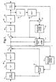
- a known transcoder as shown in Figure 1 can be perceived as comprising a decoder 28 and an encoder 30.
- the decoder 28 comprises a variable length decoder 2 which receives a video signal encoded according to a first coding scheme employing motion compensation and DCT coding of the difference signals, say a 64 kbit/s signal conforming to CCITT H.261 standard.
- the decoder 2 detects and converts the received data into quantised DCT coefficients, quantisation indexes and motion vectors.
- the DCT coefficients are passed through an inverse quantiser 4 and an inverse DCT processor 6 which converts the DCT coefficients into pixel difference values.
- the motion vectors are passed to a motion compensator 8 which calculates the address of the prediction pixel block in the previous frame.
- This block is then retrieved from a previous frame store 12 and added in adder 10 to the output of the inverse DCT processor 6 to produce a decoded data stream for the current block.
- the decoded data stream is stored in the previous frame store 12 as a reference for the next frame.
- the decoded data stream also passes into the encoder 30 of the transcoder and a motion estimator 14 searches a previous frame buffer 16 for an offset block of pixels that closely resembles the current block.
- the motion vector for this best-match block is calculated and the block retrieved from the previous frame buffer 16 and subtracted by means 15 from the decoded data stream to form a difference signal.
- This difference signal for the current block is then transformed into the frequency domain by a DCT processor 18.
- the frequency coefficients thus generated are then quantised in a quantiser 20 having a step size suitable for the bit rate desired at the transcoder's output.
- a variable length coder 22 converts the output of the quantiser 20 and the motion vectors from the motion estimator 14 into variable length codes and then outputs the data in the new format.
- the encoder 30 of the transcoder also includes a local decoder which comprises an inverse quantiser 24 and an inverse DCT processor 26.
- the output of the inverse DCT processor 26 and the motion estimator and compensator 14 are input to an adder 27 to produce an updated predicted frame which is stored in the previous frame store 16.
- the transcoder comprises a variable length decoder 40, for decoding incoming signals encoded according to a first format, for instance in accordance with CCITT standard H.261 at 64kbit/s.
- the decoder 40 detects and converts the variable length codes into DCT coefficients and motion vectors and the latter are passed through the transcoder without any further processing as indicated by numeral 42.
- Such a transcoder is suitable for use with coding schemes having the same picture resolution, transform block size and motion compensation block size.
- the DCT coefficients are then input to an inverse quantiser 44 and the resulting data requantised by quantiser 46 with a different quantisation step size appropriate to the output format, for instance 32kbit/s.
- the new DCT coefficients are encoded by a variable length coder 48 and then recombined with the unmodified motion vectors 42 in a multiplexer 50.
- the decoding is performed on the coded data directly from the transmission system without buffering and there is very little delay up to the output of the multiplexer 50 because the processes have low latency.
- the only buffer that may be necessary may be between the multiplexer and the output of the transcoder and serves the same two functions as in a normal encoder; namely smoothing the coded data and providing additional control of the quantiser 46.
- the smoothing required is only to cover any localised variations in output rate due to the discrete nature of the quantiser 46, so this buffer (not shown) and its delay can be an order of magnitude or more smaller than those in conventional encoders.
- the quantiser 46 introduces quantisation error into the output of the transcoder which is not foreseen by the original encoder.
- Decoded images formed at the final decoder will therefore contain artefacts which will increase with time unless non-predictive coding is occasionally employed to restore the integrity of the decoded signal.
- the original encoder may not employ non-predictive coding sufficiently often for an acceptable decoded image to be constructed at the destination encoder if a transcoder is employed of which the original encoder is not aware. This will result in a drift between the video signal received by the transcoder and that output from the transcoder. This error or drift will build up over time unless this drift is compensated for. Thus we apply a correction within the transcoder itself.
- the concept is to requantise the transform coefficients as quickly as possible, accept that mistracking will be introduced between the original encoder (not shown) and the eventual decoder (not shown), dispatch the coded data to the eventual decoder, compute the error being introduced and attempt to correct it at the next opportunity.
- mistracking will be introduced between the original encoder (not shown) and the eventual decoder (not shown)
- dispatch the coded data to the eventual decoder
- compute the error being introduced and attempt to correct it at the next opportunity.
- a new error will be introduced by requantising the then current coefficients.
- each correction can rarely be perfect given the discrete natures of the two quantising laws.
- the transcoder is continuously attempting to "catch up" with previous errors it caused.
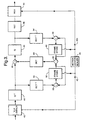
- Figure 3 shows a transcoder according to a first embodiment of the invention which is suitable for use with coding schemes having different picture resolutions, for instance a first coding scheme having a picture resolution of, say, 388x288 pixels and a second coding scheme having a picture resolution of, say, 176x144 pixels.
- a motion vector scaler 45 scales the incoming motion vectors 42 by a factor of 0.5 and the resulting motion vectors 42a are multiplexed with the output of the VLC, as described with reference to Figure 2.
- the transcoder according to Figure 3 includes the drift compensation means discussed above.
- the output from the inverse quantiser 44 is fed to an inverse DCT processor 52 and the output of quantiser 46 is fed to an inverse DCT processor 54.
- the resulting pixel difference values are passed, via adders 56,58 respectively, into frame stores 60,62 respectively, the contents of which are compensated by the original motion vectors 42 and the scaled motion vectors 42a respectively.
- After a delay of one frame the contents of the frame stores 60,62 are subtracted by subtractor 63 to form a drift signal between the received data (stored in frame store 60) and the transmitted data (stored in frame store 62).
- This drift signal is then converted back into the frequency domain by a DCT processor 64 and added to the output of the inverse quantiser 44 by adder 65.
- the drift is thus compensated for after a delay of one frame.
- the motion compensated contents of the frame stores 60,62 also form the second inputs to the adders 56,58 respectively.
- the error or drift is obtained by fully decoding to the pel domain both the original coded data and the bit rate reduced version and forming the difference. This is then transformed and added back into the main path just before the quantiser. Note that the reconstructed video signals used to form the error are taken from the outputs of the picture stores and are thus one picture late with respect to the main path.
- FIG. 4 shows an alternative embodiment of a transcoder according to the invention, which is suitable for coding schemes having the same picture resolution, transform block size and motion compensation block size. Similar components are indicated by the same reference numerals.
- the drift signal is formed in the frequency domain as opposed to the pixel domain.
- the outputs of the inverse quantiser 44 and the quantiser 46 are input to a subtractor 70 to form a drift signal between the DCT coefficients of the received and transmitted signal.
- This drift signal is then converted to the pixel domain by inverse DCT processor 72.
- the output from the inverse DCT processor 72 forms one input to an adder 74, the output of which is passed to a frame store 76.
- the contents of the frame store are transformed back into the frequency domain by a DCT processor 78.
- the contents of the frame store also form the second input to the adder 74.
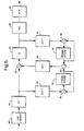
- FIG. 5 shows a further embodiment of a transcoder according to the invention which is suitable for use with coding schemes that do not employ motion compensation techniques.
- a transcoder includes drift compensation means and is suitable for use with video signals as well as other signals.
- similar components are indicated by the same reference numbers.
- the transcoder of Figure 5 operates in a manner similar to that shown in Figure 3. When no motion compensation is involved, the drift compensation may be calculated fully in the transform domain.
- VBR Variable Bit Rate
- An example with special relevance to packet video is a connection between a terminal connected to an Integrated Services Digital Network (ISDN) and another on a Local Area Network (LAN), as shown in Figure 6.
- ISDN Integrated Services Digital Network
- LAN Local Area Network
- Compressed video from the ISDN terminal at a constant rate is transferred unchanged to the LAN by a gateway transcoder 80 when the LAN traffic is sufficiently low.
- the gateway transcoder 80 is able to reduce the video data rate required on the LAN. No control mechanism back to the original encoder 84 is necessary.
- the transcoder is able to make rate changes of almost arbitrary size and at arbitrary instants compared to, for example, the discrete 64 kbit/s or so steps at 20 millisecond boundaries possible in H.320/H.221.
- ARQ Automatic Repeat reQuest
- the transcoder is normally inactive with the quantisation index of the inverse quantiser 44 and the quantiser 46 being equal.
- the picture quality therefore is not impaired by the transcoder.
- the bit rate reduction of the transcoder 80 is only invoked for comparatively short periods to mitigate against a transmission problem. Any temporary drop of picture quality is much more preferable than the usual effects of data loss on a predictive algorithm.
- a transcoder according to the invention is also suitable for use for converting constant bit rate data from a terminal, for instance a terminal 86 of the LAN, into VBR data for transmission via an ATM network.
- the coded data from the transcoder of the invention may be transmitted to a decoder that operates at the transmitted data rate or to a decoder that operates at a higher data rate, e.g. that of the original encoder.
Description
Claims (8)
- A transcoder comprising a decoder (40,44) for decoding an input video signal encoded according to a first coding scheme employing predictive coding, to produce an intermediate signal, and an encoder (46, 48) for recoding the intermediate signal according to a second coding scheme employing predictive coding, characterised in that the decoder is arranged partially to decode the input video signal to produce the intermediate signal, and that the transcoder further comprises drift compensation means (52-65; 70-78 & 65) having inter-frame predictive decoding means operable, upon the recoding by the encoder of a given frame of the intermediate signal, to estimate error introduced by the recoding and to apply a correction signal to the recoding of a later portion of the signal.
- A transcoder according to Claim 1 in which the drift compensation means comprises(a) first predictive decoding means (52, 56, 60) fully to decode the intermediate signal;(b) second predictive decoding means (54, 58, 62) fully to decode an output of the encoder; and(c) means (63, 64) for forming the correction signal from the difference between the outputs of the first and second predictive decoding means.
- A transcoder according to Claim 1 in which the drift compensation means comprises(a) means (70) for subtracting the intermediate signal and an output of the encoder to form a difference signal; and(b) means (74, 76) for predictive decoding of the difference signal to form the correction signal.
- A transcoder according to Claim 3 wherein both coding schemes employ transform coding and wherein the subtracting means (70) is connected to receive signals in the frequency domain, and the transcoder further includes inverse transform means (72) for converting the difference signal into the pixel domain and means (78) for transforming the correction signal back into the frequency domain.
- A transcoder according to any one of the preceding Claims wherein the drift compensation means is arranged to apply the correction signal only if the correction signal exceeds a threshold.
- A transcoder according to any one of the preceding Claims wherein the decoder includes an inverse quantiser (44) and the encoder includes a quantiser (46) of different quantisation step size from that of the inverse quantiser (44).
- A transcoder according to any one of the preceding Claims in which said coding schemes employ motion compensated predictive coding and the transcoder further comprises means (45, 50) operable to extract the motion compensation information from the input video signal, to modify the motion compensation information in accordance with the relative properties of the two coding schemes and to combine the motion compensation information with the recoded video signal.
- A transcoder according to Claim 7 in which the means (45, 50) to extract, modify and combine the motion compensation information is arranged to scale the motion compensation information in accordance with the relative resolutions of the two coding schemes.
Priority Applications (1)
| Application Number | Priority Date | Filing Date | Title |
|---|---|---|---|
| EP95915946A EP0756803B1 (en) | 1994-04-21 | 1995-04-21 | A transcoder |
Applications Claiming Priority (7)
| Application Number | Priority Date | Filing Date | Title |
|---|---|---|---|
| EP94302829 | 1994-04-21 | ||
| SG1996003023A SG43051A1 (en) | 1994-04-21 | 1994-04-21 | A transcoder |
| EP94302829 | 1994-04-21 | ||
| GB9414579 | 1994-07-19 | ||
| GB9414579A GB9414579D0 (en) | 1994-04-21 | 1994-07-19 | |
| PCT/GB1995/000906 WO1995029561A1 (en) | 1994-04-21 | 1995-04-21 | A transcoder |
| EP95915946A EP0756803B1 (en) | 1994-04-21 | 1995-04-21 | A transcoder |
Publications (2)
| Publication Number | Publication Date |
|---|---|
| EP0756803A1 EP0756803A1 (en) | 1997-02-05 |
| EP0756803B1 true EP0756803B1 (en) | 2000-03-29 |
Family
ID=27236117
Family Applications (1)
| Application Number | Title | Priority Date | Filing Date |
|---|---|---|---|
| EP95915946A Expired - Lifetime EP0756803B1 (en) | 1994-04-21 | 1995-04-21 | A transcoder |
Country Status (10)
| Country | Link |
|---|---|
| EP (1) | EP0756803B1 (en) |
| JP (1) | JP3614857B2 (en) |
| CN (1) | CN1090425C (en) |
| AU (1) | AU696085B2 (en) |
| CA (1) | CA2187793C (en) |
| DE (1) | DE69515997T2 (en) |
| ES (1) | ES2145273T3 (en) |
| NZ (2) | NZ284127A (en) |
| SG (1) | SG43051A1 (en) |
| WO (1) | WO1995029561A1 (en) |
Families Citing this family (19)
| Publication number | Priority date | Publication date | Assignee | Title |
|---|---|---|---|---|
| CA2249606C (en) * | 1996-04-12 | 2005-01-25 | Imedia Corporation | Video transcoder |
| GB9611511D0 (en) * | 1996-06-03 | 1996-08-07 | Digi Media Vision Ltd | Improvements in or relating to the bit-rate of a signal |
| SE515535C2 (en) * | 1996-10-25 | 2001-08-27 | Ericsson Telefon Ab L M | A transcoder |
| EP0927495A4 (en) * | 1997-07-22 | 2001-05-30 | Koninkl Philips Electronics Nv | Method of switching between video sequences and corresponding device |
| KR100592651B1 (en) | 1997-11-27 | 2006-06-23 | 브리티쉬 텔리커뮤니케이션즈 파블릭 리미티드 캄퍼니 | Transcoding |
| US6775325B1 (en) * | 1998-10-07 | 2004-08-10 | Sarnoff Corporation | Method and apparatus for converting the bitrate of an encoded bitstream without full re-encoding |
| US6532593B1 (en) * | 1999-08-17 | 2003-03-11 | General Instrument Corporation | Transcoding for consumer set-top storage application |
| US6441754B1 (en) | 1999-08-17 | 2002-08-27 | General Instrument Corporation | Apparatus and methods for transcoder-based adaptive quantization |
| KR20010092795A (en) * | 1999-11-23 | 2001-10-26 | 요트.게.아. 롤페즈 | Seamless switching of MPEG video streams |
| US6847406B2 (en) * | 2000-12-06 | 2005-01-25 | Koninklijke Philips Electronics N.V. | High quality, cost-effective film-to-video converter for high definition television |
| EP1442599A1 (en) * | 2001-10-29 | 2004-08-04 | Koninklijke Philips Electronics N.V. | Compression |
| EP1559275A1 (en) * | 2002-11-01 | 2005-08-03 | Nokia Corporation | A method and device for transcoding images |
| US20050111545A1 (en) | 2003-11-25 | 2005-05-26 | Ram Prabhakar | Dynamic packet size control for MPEG-4 data partition mode |
| JP4534935B2 (en) * | 2005-10-04 | 2010-09-01 | 株式会社日立製作所 | Transcoder, recording apparatus, and transcoding method |
| US8705630B2 (en) | 2006-02-10 | 2014-04-22 | Nvidia Corporation | Adapting one type of encoder to another type of encoder |
| US7966361B1 (en) | 2006-02-10 | 2011-06-21 | Nvidia Corporation | Single-cycle modulus operation |
| JP5022812B2 (en) * | 2007-08-06 | 2012-09-12 | ザインエレクトロニクス株式会社 | Image signal processing device |
| JP5709492B2 (en) * | 2010-12-01 | 2015-04-30 | 三菱電機株式会社 | Image coding method conversion apparatus and image coding method conversion program |
| CN106231315B (en) * | 2016-08-05 | 2019-06-14 | 北京数码视讯科技股份有限公司 | A kind of video coding system and the method for video coding using the system |
Citations (2)
| Publication number | Priority date | Publication date | Assignee | Title |
|---|---|---|---|---|
| EP0637893A1 (en) * | 1993-08-04 | 1995-02-08 | Koninklijke KPN N.V. | Transcoding device |
| WO1995019072A1 (en) * | 1994-01-07 | 1995-07-13 | Codex Corporation | Efficient transcoding device and method |
Family Cites Families (4)
| Publication number | Priority date | Publication date | Assignee | Title |
|---|---|---|---|---|
| US5253244A (en) * | 1980-07-16 | 1993-10-12 | Discovision Associates | System for recording digital information in a pulse-length modulation format |
| JPS57166640A (en) * | 1981-04-03 | 1982-10-14 | Hitachi Ltd | Data transmission converting system of buffer device |
| NL8402411A (en) * | 1984-08-02 | 1986-03-03 | Philips Nv | DEVICE FOR CORRECTING AND MASKING ERRORS IN AN INFORMATION FLOW, AND DISPLAY FOR DISPLAYING IMAGES AND / OR SOUND PROVIDED WITH SUCH A DEVICE. |
| JPH04192080A (en) * | 1990-11-27 | 1992-07-10 | Mitsubishi Electric Corp | Picture memory device and picture data processing method |
-
1994
- 1994-04-21 SG SG1996003023A patent/SG43051A1/en unknown
-
1995
- 1995-04-21 AU AU22637/95A patent/AU696085B2/en not_active Ceased
- 1995-04-21 CA CA002187793A patent/CA2187793C/en not_active Expired - Fee Related
- 1995-04-21 DE DE69515997T patent/DE69515997T2/en not_active Expired - Lifetime
- 1995-04-21 EP EP95915946A patent/EP0756803B1/en not_active Expired - Lifetime
- 1995-04-21 NZ NZ284127A patent/NZ284127A/en not_active IP Right Cessation
- 1995-04-21 JP JP52745895A patent/JP3614857B2/en not_active Expired - Fee Related
- 1995-04-21 WO PCT/GB1995/000906 patent/WO1995029561A1/en active IP Right Grant
- 1995-04-21 NZ NZ329781A patent/NZ329781A/en not_active IP Right Cessation
- 1995-04-21 ES ES95915946T patent/ES2145273T3/en not_active Expired - Lifetime
- 1995-04-21 CN CN95192691A patent/CN1090425C/en not_active Expired - Fee Related
Patent Citations (2)
| Publication number | Priority date | Publication date | Assignee | Title |
|---|---|---|---|---|
| EP0637893A1 (en) * | 1993-08-04 | 1995-02-08 | Koninklijke KPN N.V. | Transcoding device |
| WO1995019072A1 (en) * | 1994-01-07 | 1995-07-13 | Codex Corporation | Efficient transcoding device and method |
Also Published As
| Publication number | Publication date |
|---|---|
| DE69515997D1 (en) | 2000-05-04 |
| CA2187793C (en) | 2000-05-30 |
| EP0756803A1 (en) | 1997-02-05 |
| AU2263795A (en) | 1995-11-16 |
| SG43051A1 (en) | 1997-10-17 |
| CN1090425C (en) | 2002-09-04 |
| JP3614857B2 (en) | 2005-01-26 |
| WO1995029561A1 (en) | 1995-11-02 |
| NZ284127A (en) | 1998-04-27 |
| AU696085B2 (en) | 1998-09-03 |
| CN1146840A (en) | 1997-04-02 |
| JPH09512395A (en) | 1997-12-09 |
| CA2187793A1 (en) | 1995-11-02 |
| ES2145273T3 (en) | 2000-07-01 |
| NZ329781A (en) | 1999-10-28 |
| DE69515997T2 (en) | 2000-11-02 |
Similar Documents
| Publication | Publication Date | Title |
|---|---|---|
| US5940130A (en) | Video transcoder with by-pass transfer of extracted motion compensation data | |
| EP0756803B1 (en) | A transcoder | |
| EP0691054B1 (en) | Efficient transcoding device and method | |
| KR100188423B1 (en) | Apparatus and method for adaptively compressing successive blocks of digital video | |
| EP0538667B1 (en) | Adaptive motion compensation using a plurality of motion compensators | |
| US5870146A (en) | Device and method for digital video transcoding | |
| AU685444B2 (en) | A transcoder | |
| AU744535B2 (en) | Transcoding | |
| US5434622A (en) | Image signal encoding apparatus using adaptive frame/field format compression | |
| EP0585051B1 (en) | Image processing method and apparatus | |
| US6912253B1 (en) | Method and apparatus for transcoding coded video image data | |
| KR20010070539A (en) | A method for computational graceful degradation in an audiovisual compression system | |
| JP2006518568A (en) | Video encoding | |
| JP3855522B2 (en) | Video converter | |
| US20080123748A1 (en) | Compression circuitry for generating an encoded bitstream from a plurality of video frames | |
| KR19980017213A (en) | Image Decoding System with Compensation Function for Degraded Image | |
| JP4153150B2 (en) | Transcoding method and transcoding apparatus for moving image encoded data | |
| KR20020001769A (en) | Transcoding method and device | |
| KR100386374B1 (en) | A transcoder | |
| JP4164903B2 (en) | Video code string conversion apparatus and method | |
| KR0181067B1 (en) | Moving picture encoder of having compatibility | |
| US20030086493A1 (en) | Compression | |
| JPH0216887A (en) | Picture encodor | |
| KR100235357B1 (en) | Pyramidal decoding apparatus for the concealment of cell loss in progressive transmission | |
| JPH07203442A (en) | Digital transmitter |
Legal Events
| Date | Code | Title | Description |
|---|---|---|---|
| PUAI | Public reference made under article 153(3) epc to a published international application that has entered the european phase |
Free format text: ORIGINAL CODE: 0009012 |
|
| 17P | Request for examination filed |
Effective date: 19961004 |
|
| AK | Designated contracting states |
Kind code of ref document: A1 Designated state(s): BE CH DE DK ES FR GB IT LI NL SE |
|
| 17Q | First examination report despatched |
Effective date: 19971128 |
|
| GRAG | Despatch of communication of intention to grant |
Free format text: ORIGINAL CODE: EPIDOS AGRA |
|
| GRAG | Despatch of communication of intention to grant |
Free format text: ORIGINAL CODE: EPIDOS AGRA |
|
| GRAH | Despatch of communication of intention to grant a patent |
Free format text: ORIGINAL CODE: EPIDOS IGRA |
|
| GRAH | Despatch of communication of intention to grant a patent |
Free format text: ORIGINAL CODE: EPIDOS IGRA |
|
| GRAA | (expected) grant |
Free format text: ORIGINAL CODE: 0009210 |
|
| AK | Designated contracting states |
Kind code of ref document: B1 Designated state(s): BE CH DE DK ES FR GB IT LI NL SE |
|
| PG25 | Lapsed in a contracting state [announced via postgrant information from national office to epo] |
Ref country code: SE Free format text: THE PATENT HAS BEEN ANNULLED BY A DECISION OF A NATIONAL AUTHORITY Effective date: 20000329 |
|
| REG | Reference to a national code |
Ref country code: CH Ref legal event code: EP |
|
| REF | Corresponds to: |
Ref document number: 69515997 Country of ref document: DE Date of ref document: 20000504 |
|
| ITF | It: translation for a ep patent filed |
Owner name: JACOBACCI & PERANI S.P.A. |
|
| PG25 | Lapsed in a contracting state [announced via postgrant information from national office to epo] |
Ref country code: DK Free format text: LAPSE BECAUSE OF FAILURE TO SUBMIT A TRANSLATION OF THE DESCRIPTION OR TO PAY THE FEE WITHIN THE PRESCRIBED TIME-LIMIT Effective date: 20000629 |
|
| REG | Reference to a national code |
Ref country code: ES Ref legal event code: FG2A Ref document number: 2145273 Country of ref document: ES Kind code of ref document: T3 |
|
| REG | Reference to a national code |
Ref country code: CH Ref legal event code: NV Representative=s name: JACOBACCI & PERANI S.A. |
|
| ET | Fr: translation filed | ||
| PLBE | No opposition filed within time limit |
Free format text: ORIGINAL CODE: 0009261 |
|
| STAA | Information on the status of an ep patent application or granted ep patent |
Free format text: STATUS: NO OPPOSITION FILED WITHIN TIME LIMIT |
|
| 26N | No opposition filed | ||
| REG | Reference to a national code |
Ref country code: GB Ref legal event code: IF02 |
|
| PGFP | Annual fee paid to national office [announced via postgrant information from national office to epo] |
Ref country code: DE Payment date: 20120420 Year of fee payment: 18 Ref country code: NL Payment date: 20120425 Year of fee payment: 18 |
|
| PGFP | Annual fee paid to national office [announced via postgrant information from national office to epo] |
Ref country code: FR Payment date: 20120507 Year of fee payment: 18 |
|
| PGFP | Annual fee paid to national office [announced via postgrant information from national office to epo] |
Ref country code: CH Payment date: 20121026 Year of fee payment: 18 Ref country code: BE Payment date: 20121026 Year of fee payment: 18 |
|
| PGFP | Annual fee paid to national office [announced via postgrant information from national office to epo] |
Ref country code: ES Payment date: 20121029 Year of fee payment: 18 Ref country code: IT Payment date: 20121026 Year of fee payment: 18 |
|
| BERE | Be: lapsed |
Owner name: BRITISH *TELECOMMUNICATIONS P.L.C. Effective date: 20130430 |
|
| REG | Reference to a national code |
Ref country code: NL Ref legal event code: V1 Effective date: 20131101 |
|
| REG | Reference to a national code |
Ref country code: CH Ref legal event code: PL |
|
| PG25 | Lapsed in a contracting state [announced via postgrant information from national office to epo] |
Ref country code: LI Free format text: LAPSE BECAUSE OF NON-PAYMENT OF DUE FEES Effective date: 20130430 Ref country code: CH Free format text: LAPSE BECAUSE OF NON-PAYMENT OF DUE FEES Effective date: 20130430 Ref country code: DE Free format text: LAPSE BECAUSE OF NON-PAYMENT OF DUE FEES Effective date: 20131101 Ref country code: BE Free format text: LAPSE BECAUSE OF NON-PAYMENT OF DUE FEES Effective date: 20130430 |
|
| REG | Reference to a national code |
Ref country code: FR Ref legal event code: ST Effective date: 20131231 |
|
| REG | Reference to a national code |
Ref country code: DE Ref legal event code: R119 Ref document number: 69515997 Country of ref document: DE Effective date: 20131101 |
|
| PG25 | Lapsed in a contracting state [announced via postgrant information from national office to epo] |
Ref country code: IT Free format text: LAPSE BECAUSE OF NON-PAYMENT OF DUE FEES Effective date: 20130421 Ref country code: NL Free format text: LAPSE BECAUSE OF NON-PAYMENT OF DUE FEES Effective date: 20131101 Ref country code: FR Free format text: LAPSE BECAUSE OF NON-PAYMENT OF DUE FEES Effective date: 20130430 |
|
| REG | Reference to a national code |
Ref country code: ES Ref legal event code: FD2A Effective date: 20140606 |
|
| PGFP | Annual fee paid to national office [announced via postgrant information from national office to epo] |
Ref country code: GB Payment date: 20140422 Year of fee payment: 20 |
|
| PG25 | Lapsed in a contracting state [announced via postgrant information from national office to epo] |
Ref country code: ES Free format text: LAPSE BECAUSE OF NON-PAYMENT OF DUE FEES Effective date: 20130422 |
|
| REG | Reference to a national code |
Ref country code: GB Ref legal event code: PE20 Expiry date: 20150420 |
|
| PG25 | Lapsed in a contracting state [announced via postgrant information from national office to epo] |
Ref country code: GB Free format text: LAPSE BECAUSE OF EXPIRATION OF PROTECTION Effective date: 20150420 |