EP0756472B1 - Dispositif de stabilisation d'ancrage orthopedique - Google Patents
Dispositif de stabilisation d'ancrage orthopedique Download PDFInfo
- Publication number
- EP0756472B1 EP0756472B1 EP95918025A EP95918025A EP0756472B1 EP 0756472 B1 EP0756472 B1 EP 0756472B1 EP 95918025 A EP95918025 A EP 95918025A EP 95918025 A EP95918025 A EP 95918025A EP 0756472 B1 EP0756472 B1 EP 0756472B1
- Authority
- EP
- European Patent Office
- Prior art keywords
- anchor
- clip
- hook
- vertebra
- stabilising
- Prior art date
- Legal status (The legal status is an assumption and is not a legal conclusion. Google has not performed a legal analysis and makes no representation as to the accuracy of the status listed.)
- Expired - Lifetime
Links
- 230000000399 orthopedic effect Effects 0.000 title description 16
- 230000000087 stabilizing effect Effects 0.000 title description 11
- 238000004873 anchoring Methods 0.000 claims description 39
- 210000000988 bone and bone Anatomy 0.000 claims description 17
- 230000003019 stabilising effect Effects 0.000 claims 10
- 230000006641 stabilisation Effects 0.000 description 38
- 238000011105 stabilization Methods 0.000 description 29
- 208000031968 Cadaver Diseases 0.000 description 21
- 241000251539 Vertebrata <Metazoa> Species 0.000 description 4
- 230000010355 oscillation Effects 0.000 description 3
- 238000012423 maintenance Methods 0.000 description 2
- 238000000034 method Methods 0.000 description 2
- 235000020004 porter Nutrition 0.000 description 2
- 238000013519 translation Methods 0.000 description 2
- 230000001054 cortical effect Effects 0.000 description 1
- 238000003780 insertion Methods 0.000 description 1
- 230000037431 insertion Effects 0.000 description 1
- 238000009434 installation Methods 0.000 description 1
- 230000000149 penetrating effect Effects 0.000 description 1
- 238000012545 processing Methods 0.000 description 1
- 230000000284 resting effect Effects 0.000 description 1
- 239000007787 solid Substances 0.000 description 1
Images



Classifications
-
- A—HUMAN NECESSITIES
- A61—MEDICAL OR VETERINARY SCIENCE; HYGIENE
- A61B—DIAGNOSIS; SURGERY; IDENTIFICATION
- A61B17/00—Surgical instruments, devices or methods
- A61B17/56—Surgical instruments or methods for treatment of bones or joints; Devices specially adapted therefor
- A61B17/58—Surgical instruments or methods for treatment of bones or joints; Devices specially adapted therefor for osteosynthesis, e.g. bone plates, screws or setting implements
- A61B17/68—Internal fixation devices, including fasteners and spinal fixators, even if a part thereof projects from the skin
- A61B17/70—Spinal positioners or stabilisers, e.g. stabilisers comprising fluid filler in an implant
- A61B17/7001—Screws or hooks combined with longitudinal elements which do not contact vertebrae
- A61B17/7044—Screws or hooks combined with longitudinal elements which do not contact vertebrae also having plates, staples or washers bearing on the vertebrae
-
- A—HUMAN NECESSITIES
- A61—MEDICAL OR VETERINARY SCIENCE; HYGIENE
- A61B—DIAGNOSIS; SURGERY; IDENTIFICATION
- A61B17/00—Surgical instruments, devices or methods
- A61B17/56—Surgical instruments or methods for treatment of bones or joints; Devices specially adapted therefor
- A61B17/58—Surgical instruments or methods for treatment of bones or joints; Devices specially adapted therefor for osteosynthesis, e.g. bone plates, screws or setting implements
- A61B17/68—Internal fixation devices, including fasteners and spinal fixators, even if a part thereof projects from the skin
- A61B17/70—Spinal positioners or stabilisers, e.g. stabilisers comprising fluid filler in an implant
- A61B17/7001—Screws or hooks combined with longitudinal elements which do not contact vertebrae
- A61B17/7041—Screws or hooks combined with longitudinal elements which do not contact vertebrae with single longitudinal rod offset laterally from single row of screws or hooks
-
- A—HUMAN NECESSITIES
- A61—MEDICAL OR VETERINARY SCIENCE; HYGIENE
- A61B—DIAGNOSIS; SURGERY; IDENTIFICATION
- A61B17/00—Surgical instruments, devices or methods
- A61B17/064—Surgical staples, i.e. penetrating the tissue
- A61B17/0642—Surgical staples, i.e. penetrating the tissue for bones, e.g. for osteosynthesis or connecting tendon to bone
-
- A—HUMAN NECESSITIES
- A61—MEDICAL OR VETERINARY SCIENCE; HYGIENE
- A61B—DIAGNOSIS; SURGERY; IDENTIFICATION
- A61B17/00—Surgical instruments, devices or methods
- A61B17/56—Surgical instruments or methods for treatment of bones or joints; Devices specially adapted therefor
- A61B17/58—Surgical instruments or methods for treatment of bones or joints; Devices specially adapted therefor for osteosynthesis, e.g. bone plates, screws or setting implements
- A61B17/68—Internal fixation devices, including fasteners and spinal fixators, even if a part thereof projects from the skin
- A61B17/80—Cortical plates, i.e. bone plates; Instruments for holding or positioning cortical plates, or for compressing bones attached to cortical plates
- A61B17/8028—Cushions, i.e. elements forming interface between bone plate and bone
-
- A—HUMAN NECESSITIES
- A61—MEDICAL OR VETERINARY SCIENCE; HYGIENE
- A61B—DIAGNOSIS; SURGERY; IDENTIFICATION
- A61B17/00—Surgical instruments, devices or methods
- A61B17/064—Surgical staples, i.e. penetrating the tissue
- A61B2017/0641—Surgical staples, i.e. penetrating the tissue having at least three legs as part of one single body
-
- A—HUMAN NECESSITIES
- A61—MEDICAL OR VETERINARY SCIENCE; HYGIENE
- A61B—DIAGNOSIS; SURGERY; IDENTIFICATION
- A61B17/00—Surgical instruments, devices or methods
- A61B17/064—Surgical staples, i.e. penetrating the tissue
- A61B2017/0647—Surgical staples, i.e. penetrating the tissue having one single leg, e.g. tacks
-
- A—HUMAN NECESSITIES
- A61—MEDICAL OR VETERINARY SCIENCE; HYGIENE
- A61B—DIAGNOSIS; SURGERY; IDENTIFICATION
- A61B17/00—Surgical instruments, devices or methods
- A61B17/064—Surgical staples, i.e. penetrating the tissue
- A61B2017/0647—Surgical staples, i.e. penetrating the tissue having one single leg, e.g. tacks
- A61B2017/0648—Surgical staples, i.e. penetrating the tissue having one single leg, e.g. tacks threaded, e.g. tacks with a screw thread
Definitions
- the present invention relates to anchors such as screws pedicle and hooks used for instrumentation of the spine, which are placed on the vertebrae to form anchors connected to each other by one or more connecting rods.
- the orthopedic hooks that are commonly used for the instrumentation of the spine are shaped to hang on a part vertebrae.
- a hook comprises a hook body comprising a inner support face and an outer fixing face provided with means for attachment to an anchoring rod, and a blade curved forming with the inner face of the body a U-shaped profile for wrap said portion of vertebra.
- the curved blade includes a traction branch generally opposite to the inside of the body which it is connected by a connecting branch.
- a first mode of use they are oriented towards top: they are slid between two articulars and are supported by the scalloped end of their blade on the pedicle of the vertebra, and by the hollow of their U-shaped profile under the shoulder of the lower articular and the blade inside.
- a second mode of use they are oriented towards the top: they are slid under the vertebral lamina and are supported by the hollow of their U-shaped profile on the lower edge of the blade of the vertebra.
- the hooks have little or no primary stability, i.e. they do not constitute a stable anchoring element only if combined with a second anchoring element such as another opposing hook or a fixing screw. Even in the presence of another anchor in opposition, such a hook can slide medially on the blade and escape from the support of the pedicle. It can turn in and pass in the spinal canal of the vertebra, becoming dangerous for the marrow spinal.
- an anchorage is made using a bone screw screwed into the pedicle of the vertebra.
- a pedicle screw includes a threaded external part with a low pitch thread suitable for screwing a nut, an anchor body or part intermediate of larger diameter, and a threaded internal part coaxial whose reduced pitch thread is suitable for screwing into the pedicle and in the vertebral body.
- the screw is connected to a rod connection by a clamp tightened by the nut screwed on the external part threaded.
- the screw is connected to a plate or strip of connection of which a portion is crossed by the threaded external part of screw and tightened by the nut screwed on said external threaded part.
- the internal threaded part is screwed into the bone, then adapt the rod or connecting plate on the external threaded part, and we screw the nut to achieve the reduction of vertebral deformation and securing the rod or connecting plate and the screw.
- the tightening the nut induces a torque on the pedicle screw, this which sometimes produces excessive tightening of the screw in the bone.
- Document FR-A-2 642 642 describes an anchoring hook orthopedic associated with a pedicle screw ensuring its maintenance on a vertebrate.
- the problem proposed by the present invention is to ensure the primary stabilization of the orthopedic anchorage on the vertebra, to improve bone anchoring from the preliminary stage of laying instrumentation on the spine, during the reduction stage of deformation of the spine, and throughout the subsequent period of maintenance of the spine.
- anchoring whether in the form of screws pedicle or hook, reliable and permanent stability, to avoid reduction losses in the short or medium term. It is suitable for this prohibit any rotation or oscillation of the anchor screw, any rotation or any translation of the anchor hook.
- the stabilization of a hook on a vertebra is a priori delicate. Indeed, if we try to stabilize the hook using a bone screw screwed into the vertebra, still need to find a part of solid vertebra to receive the screw: this is rarely the case; in particular, the bone of the vertebral lamina, which is naturally thin and fragile, is not suitable for receiving a bone screw.
- a solution alternative is to provide two hooks in opposition to each other and connected to each other by a clamping device allowing them move closer to each other parallel to their inner support face. Such a solution turns out to be inconvenient to use, because it is necessary to find a correct support of the two hooks simultaneously, and stabilization lateral is insufficient.
- the invention aims to achieve improved stabilization, preventing the primary rotation of the hook under the articular process and the vertebrae pedicle, in the case of a pedicle hook.
- the invention also aims to prevent primary rotation and primary translation of the hook on the vertebral blade. This stabilization is ensured during and after reduction of spinal deformation.
- the invention also aims to provide primary stabilization a pedicle screw, avoiding lateral oscillations of the screw, and preventing it from being unscrewed from the bone and being excessively screwed into the bone, and preventing its removal from the bone.
- the staple body is articulated on the anchoring body along a transverse axis.
- the clip is a part removable separate from the anchor, suitable for engaging on the face external fixing of the anchor body.
- a anchoring element with hook stabilization device comprises an orthopedic hook 1, fixing means 2 of the hook on a securing rod 52 of anchor points, and a stabilization device 3 for stabilizing the hook 1 on a vertebrate.
- the hook 1 comprises a hook body 4 having a face inner support 5 and an outer fixing face 6 provided with the means fixing 2 to the securing rod 52.
- the hook 1 comprises besides a curved blade 7, forming with the inner face 5 of the body of hook 4 a U-shaped profile intended to wrap part of the vertebra on which hook 1 must be anchored.
- the curved blade 7 includes a traction branch 8 generally opposite and parallel to the face inner support 5 of the hook body 4, to which it is connected by a connecting branch 9.
- the free end of the traction branch 8 advantageously comprises a notch 10, intended to promote the positioning of the hook under the articular process and the pedicle of a vertebrate.
- the fixing means 2 comprise a threaded fixing rod 11, protruding from the outer face 6 for fixing the hook body 4, and intended to receive a tightening jumper 12 and a nut 13.
- the jumper clamp 12 comprises two branches 14 and 15 provided with respective holes 16 and 17 for passage of the fixing rod 11, the branches 14 and 15 parallel connecting to each other by an intermediate part curved 18 intended to surround part of the securing rod 52.
- first anti-slip reliefs 19 are provided on the outer face 6 for fixing the hook body 4, and second anti-slip reliefs 20 on the corresponding face of the branch 14 of the clamping jumper 12.
- the stabilization device 3 comprises, in this mode of embodiment shown in Figures 1 to 3, a stabilizing clip comprising a staple body 21 provided with means for securing to the body hook 4, and four staple teeth 22, 23, 24 and 25 integral with the staple body 21 and developing perpendicular to the staple body 21 in the same direction.
- the staple teeth 22-25, integral with the clip body 21, develop in the interior of the U-shaped profile direction of the traction branch 8 substantially perpendicular to the inner support face 5 of the hook body 4 for penetrating, holding position, in said part of the vertebra.
- the means for securing the staple body 21 to the body hook 4 use the fixing rod 11, which passes through a hole 26 formed in the staple body 21, the fixing rod 11 then being substantially parallel to the four teeth 22-25 of the clip.
- the staple body 21 around the rod fixing 11 and on the external fixing face 6, orienting the teeth 22-25 in the direction of the hook 1.
- the means of securing the staple body 21 to hook body 4 thus allow movement relative to the staple body 21 towards and away from the hook body 4, between a withdrawal position in which the teeth 22-25 are apart of the curved hook blade 7 and a stabilization position illustrated in Figure 3 in which teeth 22-25 develop in the interior of the U-shaped hook 1 towards the branch of traction 8, substantially perpendicular to the internal support face 5 of the hook body 4, to penetrate the inserted vertebra part in the hollow of the hook 1.
- the body clip 21 comes to bear by its first face 27 on the outer face fixing 6 of the hook body 4, and the staple body 21 is pushed back towards the hook 1 by the clamping jumper 12, the bearing face of which anti-slip reliefs 20 bears against the second face 28 of the staple body 21.
- teeth 22-25 are positioned so that the stabilization overlap the hook body 4.
- teeth 22 and 23 are two lateral teeth arranged to extend beyond the lateral edges 31 and 32 of the body of hook 4.
- Teeth 24 and 25 are two front teeth protruding beyond from the free end edge 33 of the hook body 4.
- FIG. 4 illustrates a slightly different embodiment of the stabilization device 3, in which there is a body clip 21 similar to the clip body of Figures 1 to 3, and two teeth side staples 22 and 23 similar to the side teeth of the mode of realization of Figures 1 to 3.
- this device stabilization 3 of FIG. 4 comprises a single front tooth 124, placed in a substantially central position and as illustrated in the figure.
- the clip of stabilization constitutes a removable part separate from the hook 1, adapted to engage the external fixing face 6 of the hook body 4.
- FIG. 5 illustrates a different embodiment according to the invention, in which the clip body 21 is articulated on the body of hook 4 along a transverse axis 34 disposed in the vicinity of the part of connection of the hook body 4 to the curved blade 7.
- the hole 26 of passage of the fixing rod 11 in the staple body 21 is open between the front teeth 24 and 25, to allow the tilting of the clip as illustrated in the figure.
- the anchoring device of FIG. 5 comprises the same elements as the anchoring device of FIGS. 1 to 3, and these elements are identified by the same reference numbers.
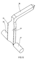
- FIG. 6 illustrate two other embodiments according to the invention for the stabilization device 3 of a hook 1 on The vertebrates.
- the staple body 21 has a shape in T, with a central branch 35 and two lateral branches 36 and 37 to circular section.
- the staple body is connected to a single tooth 38 frontal.
- Such a staple shape is intended to fit on hooks including means for fixing to a fastening rod comprise a hook body provided with a diametrical slot for passage of the securing rod, with means for clamping the rod in the hook body.
- the shape of the staple body 21 allows its insertion into the diametrical slot for the passage of the securing rod.
- Figure 7 uses the same form of staple body 21, with a central branch 35 and two lateral branches 36 and 37. The difference is that two front teeth 38 and 39 are provided. parallel to each other, as illustrated in the figure.
- the staple body 21 is adapted so that the fixing means hook 1 to a securing rod also ensure the securing of the clip 3 on the hook 1, pushing back the teeth 22-25 in the direction of the curved blade 7 to penetrate part of vertebra inserted in the hollow of the hook 1. This ensures a effective primary stabilization of hook 1 on a vertebra.
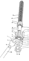
- the stabilization device is adapted to stabilize an anchoring produced by a pedicle screw 40.
- the pedicle screw 40 includes an anchoring body 41 with an inner support face 5 and a face external fixing 6, with an internal threaded rod 70 adapted to screw into the vertebra bone, and with fixing means comprising a coaxial external threaded rod 11 suitable for screwing a nut 13 for clamping a clamping jumper 12 on a securing rod 52 anchor points.
- a stabilizing clip 3 for example with four teeth 22-25 as illustrated in figure 8 according to the same structure as in the embodiment of FIGS. 1 to 3.
- the staple tooth or teeth 22-25 integral with the clip body 21, develop axially around the body anchor 41 and beyond the internal support face 5 to penetrate into the vertebral bone when the anchor is in position on the vertebra with the clip 3 resting on the external fixing face 6.
- the stabilizing clips illustrated in the figures allow to realize an orthopedic anchoring element for spinal instrumentation, including an orthopedic anchor 1, such as a hook or pedicle screw, and a stabilizing clip 3.
- an apparatus for processing the spine comprising at least one connecting rod or plate 52 connecting anchoring elements adapted to attach to the vertebrae of the spine, at least one of the anchoring elements comprising an anchoring orthopedic 1 such as a hook or a pedicle screw, and a staple of stabilization 3.
Landscapes
- Health & Medical Sciences (AREA)
- Orthopedic Medicine & Surgery (AREA)
- Life Sciences & Earth Sciences (AREA)
- Neurology (AREA)
- Surgery (AREA)
- Heart & Thoracic Surgery (AREA)
- Engineering & Computer Science (AREA)
- Biomedical Technology (AREA)
- Nuclear Medicine, Radiotherapy & Molecular Imaging (AREA)
- Medical Informatics (AREA)
- Molecular Biology (AREA)
- Animal Behavior & Ethology (AREA)
- General Health & Medical Sciences (AREA)
- Public Health (AREA)
- Veterinary Medicine (AREA)
- Surgical Instruments (AREA)
- Prostheses (AREA)
- Orthopedics, Nursing, And Contraception (AREA)
Description
- un corps d'ancrage comportant une face intérieure d'appui pour porter contre la vertèbre et une face extérieure opposée de fixation,
- des moyens d'ancrage, solidaires du corps d'ancrage, et conformés pour se fixer à la vertèbre,
- une partie de fixation, solidaire du corps d'ancrage, et munie de moyens de fixation à une tige ou plaque de solidarisation de points d'ancrage.
- un corps d'ancrage comportant une face intérieure d'appui pour porter contre la vertèbre et une face extérieure opposée de fixation,
- des moyens d' ancrage, solidaires du corps d' ancrage, et conformés pour se fixer à la vertèbre,
- une partie de fixation, solidaire du corps d'ancrage, et munie de moyens de fixation à une tige ou plaque de solidarisation de points d'ancrage.
- un corps d'agrafe , adapté pour s'engager sur la face extérieure de
fixation du corps d'ancrage, et muni de moyens de solidarisation au corps
d'ancrage, s'opposant aux rotations relatives entre le corps d'agrafe et
le corps d' ancrage, et permettant sélectivement de rapprocher le corps
d'agrafe du corps d'ancrage jusqu'à une position de stabilisation en appui
contre la face extérieure de fixation et d'éloigner le corps d'agrafe du
corps d'ancrage jusqu'à une position de libération,
- au moins une dent d'agrafe, solidaire du corps d'agrafe, orientée et conformée pour pénétrer dans la vertèbre au delà de la face intérieure d'appui du corps d'ancrage lorsque l'agrafe est en position de stabilisation sur le corps de l'ancrage lui-même adapté en position d'ancrage sur la vertèbre.
- la partie de fixation d'ancrage est une tige filetée dépassant de la face extérieure de fixation du corps d'ancrage, et destinée à recevoir un cavalier de serrage et un écrou,
- des premiers reliefs antiglissement sont ménagés sur la face extérieure de fixation du corps d'ancrage,
- des reliefs antiglissement intermédiaires correspondants sont ménagés sur les deux faces opposées du corps d'agrafe.
- des seconds reliefs antiglissement sont ménagés sur une face du cavalier de serrage.
- la figure 1 est une première vue éclatée en perspective d'un élément d'ancrage comportant un crochet orthopédique et un dispositif de stabilisation selon un premier mode de réalisation de l' invention ;
- la figure 2 est une seconde vue éclatée en perspective du dispositif de la figure 1 ;
- la figure 3 est une vue en perspective du dispositif de la figure 1, assemblé en position d' ancrage ;
- la figure 4 est une vue en perspective montrant un dispositif de stabilisation de crochet orthopédique selon un second mode de réalisation de l'invention ;
- la figure 5 est une vue en perspective illustrant un élément d'ancrage avec dispositif de stabilisation selon l'invention, dans un autre mode de réalisation ;
- la figure 6 illustre en perspective une structure de dispositif de stabilisation de crochet orthopédique selon un autre mode de réalisation de l'invention ;
- la figure 7 est une vue en perspective d'un autre mode de réalisation de dispositif de stabilisation de crochet orthopédique selon l' invention ; et
- la figure 8 est une vue en perspective illustrant une agrafe de stabilisation selon un mode de réalisation adapté à la stabilisation d'une vis pédiculaire.
Claims (10)
- Dispositif de stabilisation d'ancrage orthopédique sur une vertèbre, pour instrumentation du rachis, l'ancrage comprenant :un corps d'ancrage (4, 41) comportant une face intérieure d'appui (5) pour porter contre la vertèbre et une face extérieure opposée de fixation (6),des moyens d'ancrage (7, 70), solidaires du corps d'ancrage (4,41), et conformés pour se fixer à la vertèbre,une partie de fixation (11), solidaire du corps d'ancrage (4,41), et munie de moyens de fixation à une tige ou plaque de solidarisation (52) de points d'ancrage,
caractérisé en ce qu'il comprend une agrafe de stabilisation (3) comportant :un corps d'agrafe (21), adapté pour s'engager sur la face extérieure de fixation (6) du corps d'ancrage (4,41), et muni de moyens de solidarisation (26,34 ; 36,37) au corps d'ancrage (4,41), s'opposant aux rotations relatives entre le corps d'agrafe (21) et le corps d'ancrage (4,41), et permettant sélectivement de rapprocher le corps d'agrafe (21) du corps d'ancrage (4,41) jusqu'à une position de stabilisation en appui contre la face extérieure de fixation (6) et d'éloigner le corps d'agrafe (21) du corps d'ancrage (4,41) jusqu'à une position de libération,au moins une dent d'agrafe (22-25 ; 38 ; 39 ; 124), solidaire du corps d'agrafe (21), orientée et conformée pour pénétrer dans la vertèbre au delà de la face intérieure d'appui (5) du corps d'ancrage (4,41) lorsque l'agrafe (3) est en position de stabilisation sur le corps de l'ancrage (4,41) lui-même adapté en position d'ancrage sur la vertèbre. - Dispositif selon la revendication 1, caractérisé en ce que le corps d'agrafe (21) est articulé sur le corps d'ancrage (4,41) selon un axe transversal (34).
- Dispositif selon la revendication 1, caractérisé en ce que l'agrafe de stabilisation (3) est une pièce amovible distincte de l'ancrage, adaptée pour s'engager sur la face extérieure de fixation (6) du corps d'ancrage (4,41).
- Dispositif selon l'une quelconque des revendications 1 à 3, caractérisé en ce que :la partie de fixation d'ancrage est une tige filetée (11) dépassant de la face extérieure (6) de fixation du corps d'ancrage (4,41), et destinée à recevoir un cavalier de serrage (12) et un écrou (13),des premiers reliefs antiglissement (19) sont ménagés sur la face extérieure de fixation (6) du corps d'ancrage (4,41),des reliefs antiglissement (29, 30) intermédiaires correspondants sont ménagés sur les deux faces opposées (27,28) du corps d'agrafe (21),des seconds reliefs antiglissement (20) sont ménagés sur une face du cavalier de serrage (12).
- Dispositif de stabilisation d'ancrage orthopédique (1) selon l'une quelconque des revendications 1 à 4, dans lequel :l'ancrage est un crochet (1) comprenant un corps de crochet (4) comportant une face intérieure d'appui (5) et une face extérieure de fixation (6) munie de moyens de fixation (11, 12, 13) à une tige de solidarisation (52) de points d'ancrage, et une lame incurvée (7) formant avec la face intérieure (5) du corps (4) de crochet un profil en U pour envelopper une partie de vertèbre, avec une branche de traction (8) généralement opposée et parallèle à la face intérieure d'appui (5) de corps de crochet (4) à laquelle elle se raccorde par une branche de liaison (9),la ou les dents d'agrafe (22-25), solidaires du corps d'agrafe (21), se développent dans l'intérieur du profil en U en direction de la branche de traction (8) sensiblement perpendiculairement à la face intérieure d'appui (5) du corps de crochet (4) pour pénétrer, en position de maintien, dans ladite partie de vertèbre.
- Dispositif selon la revendication 5, caractérisé en ce que l'agrafe de stabilisation (3) comprend deux dents latérales (22, 23) dépassant au-delà des bords latéraux (31, 32) du corps de crochet (4), et au moins une dent frontale (24, 25) dépassant au-delà du bord d'extrémité libre (33) du corps de crochet (4).
- Dispositif selon la revendication 5, caractérisé en ce que l'agrafe de stabilisation (3) comprend deux dents latérales (22, 23) dépassant au-delà des bords latéraux (31, 32) du corps de crochet (4), et deux dents frontales (24, 25) dépassant au-delà du bord d'extrémité libre (33) du corps de crochet (4).
- Dispositif selon l'une quelconque des revendications 5 à 7, caractérisé en ce que les dents (22, 25) ont une longueur telle que, en position de maintien de l'agrafe (3) sur le crochet (1), l'extrémité libre des dents est légèrement en retrait de la branche de traction (8) du crochet (1).
- Dispositif de stabilisation d'ancrage orthopédique selon l'une quelconque des revendications 1 à 4, dans lequel :l'ancrage est une vis pédiculaire (40) comprenant un corps d'ancrage (41) à face intérieure d'appui (5) et à face extérieure de fixation (6), avec une tige interne filetée (70) adaptée pour se visser dans l'os de vertèbre, et avec des moyens de fixation (11, 12, 13) à une tige de solidarisation (52) de points d'ancrage,la ou les dents d'agrafe (22-25), solidaires du corps d'agrafe (21), se développent axialement autour du corps d'ancrage (41) et au delà de la face intérieure d'appui (5) pour pénétrer dans l'os vertébral lorsque l'ancrage est en position sur la vertèbre avec l'agrafe (3) en appui sur la face extérieure de fixation (6).
- Appareil de traitement du rachis, comprenant au moins une tige ou plaque de solidarisation (52) reliant des éléments d'ancrage adaptés pour se fixer aux vertèbres du rachis, caractérisé en ce que l'un au moins des éléments d'ancrage comprend un ancrage orthopédique (1) et un dispositif de stabilisation d'ancrage orthopédique (3) selon l'une quelconque des revendications 1 à 9.
Applications Claiming Priority (3)
| Application Number | Priority Date | Filing Date | Title |
|---|---|---|---|
| FR9405039 | 1994-04-20 | ||
| FR9405039A FR2718944B1 (fr) | 1994-04-20 | 1994-04-20 | Dispositif de stabilisation d'ancrage orthopédique. |
| PCT/FR1995/000507 WO1995028889A1 (fr) | 1994-04-20 | 1995-04-19 | Dispositif de stabilisation d'ancrage orthopedique |
Publications (2)
| Publication Number | Publication Date |
|---|---|
| EP0756472A1 EP0756472A1 (fr) | 1997-02-05 |
| EP0756472B1 true EP0756472B1 (fr) | 1999-07-28 |
Family
ID=9462527
Family Applications (1)
| Application Number | Title | Priority Date | Filing Date |
|---|---|---|---|
| EP95918025A Expired - Lifetime EP0756472B1 (fr) | 1994-04-20 | 1995-04-19 | Dispositif de stabilisation d'ancrage orthopedique |
Country Status (9)
| Country | Link |
|---|---|
| US (1) | US5810816A (fr) |
| EP (1) | EP0756472B1 (fr) |
| JP (1) | JP2962524B2 (fr) |
| CA (1) | CA2188299C (fr) |
| DE (1) | DE69511078T2 (fr) |
| DK (1) | DK0756472T3 (fr) |
| ES (1) | ES2136849T3 (fr) |
| FR (1) | FR2718944B1 (fr) |
| WO (1) | WO1995028889A1 (fr) |
Families Citing this family (106)
| Publication number | Priority date | Publication date | Assignee | Title |
|---|---|---|---|---|
| US6045565A (en) * | 1997-11-04 | 2000-04-04 | Scimed Life Systems, Inc. | Percutaneous myocardial revascularization growth factor mediums and method |
| EP0894477B1 (fr) * | 1997-10-06 | 2001-01-10 | Werner Hermann | Bride de serrage d'une tige de fixation, et crochet et raccord de tiges incorporants cette bride |
| US6749361B2 (en) | 1997-10-06 | 2004-06-15 | Werner Hermann | Shackle element for clamping a fixation rod, a method for making a shackle element, a hook with a shackle element and a rode connector with a shackle element |
| US6248108B1 (en) * | 1998-09-30 | 2001-06-19 | Bionx Implants Oy | Bioabsorbable surgical screw and washer system |
| US5899904A (en) * | 1998-10-19 | 1999-05-04 | Third Milennium Engineering, Llc | Compression locking vertebral body screw, staple, and rod assembly |
| US5925047A (en) * | 1998-10-19 | 1999-07-20 | Third Millennium Engineering, Llc | Coupled rod, anterior vertebral body screw, and staple assembly |
| US5899905A (en) * | 1998-10-19 | 1999-05-04 | Third Millennium Engineering Llc | Expansion locking vertebral body screw, staple, and rod assembly |
| US6132442A (en) * | 1999-03-25 | 2000-10-17 | Smith & Nephew | Graft clamp |
| US6283967B1 (en) | 1999-12-17 | 2001-09-04 | Synthes (U.S.A.) | Transconnector for coupling spinal rods |
| US6280446B1 (en) * | 1999-10-28 | 2001-08-28 | Armand N. Blackmore | Tubular splint |
| US6562038B1 (en) | 2000-03-15 | 2003-05-13 | Sdgi Holdings, Inc. | Spinal implant connection assembly |
| US6572618B1 (en) * | 2000-03-15 | 2003-06-03 | Sdgi Holdings, Inc. | Spinal implant connection assembly |
| US6872209B2 (en) * | 2000-03-15 | 2005-03-29 | Sdgi Holdings, Inc. | Spinal implant connection assembly |
| US6736816B2 (en) | 2000-06-30 | 2004-05-18 | Stephen Ritland | Polyaxial connection device and method |
| US6551318B1 (en) | 2000-07-26 | 2003-04-22 | Stahurski Consulting Inc. | Spinal column retaining apparatus |
| US7833250B2 (en) | 2004-11-10 | 2010-11-16 | Jackson Roger P | Polyaxial bone screw with helically wound capture connection |
| US6620164B2 (en) * | 2000-09-22 | 2003-09-16 | Showa Ika Kohgyo Co., Ltd. | Rod for cervical vertebra and connecting system thereof |
| US6685705B1 (en) | 2000-10-23 | 2004-02-03 | Sdgi Holdings, Inc. | Six-axis and seven-axis adjustable connector |
| US6402755B1 (en) * | 2000-12-21 | 2002-06-11 | Perumala Corporation | Plate system for bridging and stabilizing spaced apart bone segments |
| TW524094U (en) * | 2001-05-02 | 2003-03-11 | Jung-Chiuan Ye | Retaining and recovering apparatus for spines |
| US10258382B2 (en) | 2007-01-18 | 2019-04-16 | Roger P. Jackson | Rod-cord dynamic connection assemblies with slidable bone anchor attachment members along the cord |
| US7862587B2 (en) | 2004-02-27 | 2011-01-04 | Jackson Roger P | Dynamic stabilization assemblies, tool set and method |
| US8353932B2 (en) | 2005-09-30 | 2013-01-15 | Jackson Roger P | Polyaxial bone anchor assembly with one-piece closure, pressure insert and plastic elongate member |
| US8292926B2 (en) | 2005-09-30 | 2012-10-23 | Jackson Roger P | Dynamic stabilization connecting member with elastic core and outer sleeve |
| US10729469B2 (en) | 2006-01-09 | 2020-08-04 | Roger P. Jackson | Flexible spinal stabilization assembly with spacer having off-axis core member |
| US6989013B2 (en) * | 2001-09-25 | 2006-01-24 | Perumala Corporation | Medical appliance for bridging and stabilizing spaced apart bone segments having a bone screw locking system |
| AU2002327801B2 (en) | 2001-09-28 | 2008-03-06 | Stephen Ritland | Connection rod for screw or hook polyaxial system and method of use |
| US6991632B2 (en) * | 2001-09-28 | 2006-01-31 | Stephen Ritland | Adjustable rod and connector device and method of use |
| US7763047B2 (en) * | 2002-02-20 | 2010-07-27 | Stephen Ritland | Pedicle screw connector apparatus and method |
| US6682532B2 (en) | 2002-03-22 | 2004-01-27 | Depuy Acromed, Inc. | Coupling system and method for extending spinal instrumentation |
| US6966910B2 (en) | 2002-04-05 | 2005-11-22 | Stephen Ritland | Dynamic fixation device and method of use |
| EP2457529A1 (fr) | 2002-05-08 | 2012-05-30 | Stephen Ritland | Dispositif de fixation dynamique et procédé d'utilisation |
| CA2486536A1 (fr) * | 2002-05-21 | 2003-12-04 | Sdgi Holdings, Inc. | Cable de reduction et ancrage osseux |
| US8876868B2 (en) | 2002-09-06 | 2014-11-04 | Roger P. Jackson | Helical guide and advancement flange with radially loaded lip |
| US6786932B1 (en) | 2002-11-11 | 2004-09-07 | Armand N. Blackmore | Femur end implant |
| US7621918B2 (en) * | 2004-11-23 | 2009-11-24 | Jackson Roger P | Spinal fixation tool set and method |
| US20040210223A1 (en) * | 2003-04-21 | 2004-10-21 | Madhavan Pisharodi | Fastener for securing two separate workpieces |
| US7377923B2 (en) | 2003-05-22 | 2008-05-27 | Alphatec Spine, Inc. | Variable angle spinal screw assembly |
| US8262571B2 (en) | 2003-05-22 | 2012-09-11 | Stephen Ritland | Intermuscular guide for retractor insertion and method of use |
| US7967850B2 (en) | 2003-06-18 | 2011-06-28 | Jackson Roger P | Polyaxial bone anchor with helical capture connection, insert and dual locking assembly |
| US7766915B2 (en) | 2004-02-27 | 2010-08-03 | Jackson Roger P | Dynamic fixation assemblies with inner core and outer coil-like member |
| US8366753B2 (en) | 2003-06-18 | 2013-02-05 | Jackson Roger P | Polyaxial bone screw assembly with fixed retaining structure |
| US7776067B2 (en) | 2005-05-27 | 2010-08-17 | Jackson Roger P | Polyaxial bone screw with shank articulation pressure insert and method |
| US8936623B2 (en) | 2003-06-18 | 2015-01-20 | Roger P. Jackson | Polyaxial bone screw assembly |
| US7074238B2 (en) * | 2003-07-08 | 2006-07-11 | Archus Orthopedics, Inc. | Prostheses, tools and methods for replacement of natural facet joints with artificial facet joint surfaces |
| US7261715B2 (en) * | 2003-11-24 | 2007-08-28 | Sdgi Holdings, Inc. | Grommet assembly |
| US11419642B2 (en) | 2003-12-16 | 2022-08-23 | Medos International Sarl | Percutaneous access devices and bone anchor assemblies |
| US7179261B2 (en) | 2003-12-16 | 2007-02-20 | Depuy Spine, Inc. | Percutaneous access devices and bone anchor assemblies |
| US7527638B2 (en) | 2003-12-16 | 2009-05-05 | Depuy Spine, Inc. | Methods and devices for minimally invasive spinal fixation element placement |
| US7470279B2 (en) * | 2004-02-27 | 2008-12-30 | Jackson Roger P | Orthopedic implant rod reduction tool set and method |
| CA2701522C (fr) | 2004-02-27 | 2012-05-15 | Roger P. Jackson | Ensemble d'instruments de reduction de tige d'implant orthopedique et methode associee |
| US8152810B2 (en) | 2004-11-23 | 2012-04-10 | Jackson Roger P | Spinal fixation tool set and method |
| US7160300B2 (en) | 2004-02-27 | 2007-01-09 | Jackson Roger P | Orthopedic implant rod reduction tool set and method |
| US11241261B2 (en) | 2005-09-30 | 2022-02-08 | Roger P Jackson | Apparatus and method for soft spinal stabilization using a tensionable cord and releasable end structure |
| US8764801B2 (en) * | 2005-03-28 | 2014-07-01 | Gmedelaware 2 Llc | Facet joint implant crosslinking apparatus and method |
| US7455639B2 (en) | 2004-09-20 | 2008-11-25 | Stephen Ritland | Opposing parallel bladed retractor and method of use |
| US7651502B2 (en) * | 2004-09-24 | 2010-01-26 | Jackson Roger P | Spinal fixation tool set and method for rod reduction and fastener insertion |
| US8926672B2 (en) | 2004-11-10 | 2015-01-06 | Roger P. Jackson | Splay control closure for open bone anchor |
| US8444681B2 (en) | 2009-06-15 | 2013-05-21 | Roger P. Jackson | Polyaxial bone anchor with pop-on shank, friction fit retainer and winged insert |
| US9168069B2 (en) | 2009-06-15 | 2015-10-27 | Roger P. Jackson | Polyaxial bone anchor with pop-on shank and winged insert with lower skirt for engaging a friction fit retainer |
| US9216041B2 (en) | 2009-06-15 | 2015-12-22 | Roger P. Jackson | Spinal connecting members with tensioned cords and rigid sleeves for engaging compression inserts |
| WO2006057837A1 (fr) * | 2004-11-23 | 2006-06-01 | Jackson Roger P | Structure d'accrochage pour outil de fixation spinale |
| US7901437B2 (en) | 2007-01-26 | 2011-03-08 | Jackson Roger P | Dynamic stabilization member with molded connection |
| US7914536B2 (en) | 2005-03-11 | 2011-03-29 | Aesculap Ag | Bone repair device and method |
| US7585312B2 (en) * | 2005-04-29 | 2009-09-08 | Warsaw Orthopedic, Inc. | Spinal stabilization apparatus and method |
| US8177823B2 (en) * | 2005-06-30 | 2012-05-15 | Depuy Spine Sarl | Orthopedic clamping hook assembly |
| AU2006269900A1 (en) | 2005-07-19 | 2007-01-25 | Stephen Ritland | Rod extension for extending fusion construct |
| US7628799B2 (en) | 2005-08-23 | 2009-12-08 | Aesculap Ag & Co. Kg | Rod to rod connector |
| US8105368B2 (en) | 2005-09-30 | 2012-01-31 | Jackson Roger P | Dynamic stabilization connecting member with slitted core and outer sleeve |
| EP2050408B1 (fr) * | 2006-06-07 | 2011-04-13 | Disc Motion Technologies Inc. | vis pédiculaire |
| US7959564B2 (en) | 2006-07-08 | 2011-06-14 | Stephen Ritland | Pedicle seeker and retractor, and methods of use |
| US9101401B2 (en) * | 2006-11-20 | 2015-08-11 | Aesculap Implant Systems, Llc | Bone repair device and method |
| JP2010512178A (ja) | 2006-12-08 | 2010-04-22 | ロジャー・ピー・ジャクソン | 動的脊椎インプラントのためのツールシステム |
| US7744632B2 (en) | 2006-12-20 | 2010-06-29 | Aesculap Implant Systems, Inc. | Rod to rod connector |
| US8366745B2 (en) | 2007-05-01 | 2013-02-05 | Jackson Roger P | Dynamic stabilization assembly having pre-compressed spacers with differential displacements |
| US8475498B2 (en) | 2007-01-18 | 2013-07-02 | Roger P. Jackson | Dynamic stabilization connecting member with cord connection |
| US10383660B2 (en) | 2007-05-01 | 2019-08-20 | Roger P. Jackson | Soft stabilization assemblies with pretensioned cords |
| US20110172708A1 (en) * | 2007-06-22 | 2011-07-14 | Simpirica Spine, Inc. | Methods and systems for increasing the bending stiffness of a spinal segment with elongation limit |
| US20090076549A1 (en) * | 2007-09-17 | 2009-03-19 | Warsaw Orthopedic, Inc. | Orthopedic implant system |
| AU2009205575B2 (en) * | 2008-01-14 | 2014-08-28 | K2M, Inc. | Spinal fixation device and method |
| WO2010006195A1 (fr) | 2008-07-09 | 2010-01-14 | Amei Technologies, Inc. | Clou d'arthrodèse de cheville et ensemble stabilisateur |
| US8414584B2 (en) | 2008-07-09 | 2013-04-09 | Icon Orthopaedic Concepts, Llc | Ankle arthrodesis nail and outrigger assembly |
| JP2012529969A (ja) | 2008-08-01 | 2012-11-29 | ロジャー・ピー・ジャクソン | スリーブ付き張力付与りコードを備える長手方向接続部材 |
| US8998959B2 (en) | 2009-06-15 | 2015-04-07 | Roger P Jackson | Polyaxial bone anchors with pop-on shank, fully constrained friction fit retainer and lock and release insert |
| CN103826560A (zh) | 2009-06-15 | 2014-05-28 | 罗杰.P.杰克逊 | 具有套接杆和带摩擦配合压缩套爪的带翼插件的多轴骨锚 |
| CN103917181A (zh) | 2009-06-15 | 2014-07-09 | 罗杰.P.杰克逊 | 包括套接杆和具有低外形边缘锁的摩擦配合保持件的多轴骨锚 |
| US9668771B2 (en) | 2009-06-15 | 2017-06-06 | Roger P Jackson | Soft stabilization assemblies with off-set connector |
| US11229457B2 (en) | 2009-06-15 | 2022-01-25 | Roger P. Jackson | Pivotal bone anchor assembly with insert tool deployment |
| EP2485654B1 (fr) | 2009-10-05 | 2021-05-05 | Jackson P. Roger | Ancrage osseux polyaxial avec élément de rétention non rotatif et tige fixée par pression, et ajustement par frottement |
| AU2011299558A1 (en) | 2010-09-08 | 2013-05-02 | Roger P. Jackson | Dynamic stabilization members with elastic and inelastic sections |
| US9247962B2 (en) | 2011-08-15 | 2016-02-02 | K2M, Inc. | Laminar hook insertion device |
| US8911479B2 (en) | 2012-01-10 | 2014-12-16 | Roger P. Jackson | Multi-start closures for open implants |
| US8828056B2 (en) | 2012-04-16 | 2014-09-09 | Aesculap Implant Systems, Llc | Rod to rod cross connector |
| US8771319B2 (en) | 2012-04-16 | 2014-07-08 | Aesculap Implant Systems, Llc | Rod to rod cross connector |
| US8911478B2 (en) | 2012-11-21 | 2014-12-16 | Roger P. Jackson | Splay control closure for open bone anchor |
| US10058354B2 (en) | 2013-01-28 | 2018-08-28 | Roger P. Jackson | Pivotal bone anchor assembly with frictional shank head seating surfaces |
| US8852239B2 (en) | 2013-02-15 | 2014-10-07 | Roger P Jackson | Sagittal angle screw with integral shank and receiver |
| US20140277155A1 (en) | 2013-03-14 | 2014-09-18 | K2M, Inc. | Taper lock hook |
| US9566092B2 (en) | 2013-10-29 | 2017-02-14 | Roger P. Jackson | Cervical bone anchor with collet retainer and outer locking sleeve |
| US9717533B2 (en) | 2013-12-12 | 2017-08-01 | Roger P. Jackson | Bone anchor closure pivot-splay control flange form guide and advancement structure |
| US9451993B2 (en) | 2014-01-09 | 2016-09-27 | Roger P. Jackson | Bi-radial pop-on cervical bone anchor |
| US20150230828A1 (en) | 2014-02-20 | 2015-08-20 | K2M, Inc. | Spinal fixation device |
| US10064658B2 (en) | 2014-06-04 | 2018-09-04 | Roger P. Jackson | Polyaxial bone anchor with insert guides |
| US9597119B2 (en) | 2014-06-04 | 2017-03-21 | Roger P. Jackson | Polyaxial bone anchor with polymer sleeve |
| AU2018324017B2 (en) * | 2017-08-30 | 2020-08-20 | Zimmer Biomet Spine, Inc. | Dynamic stabilization system |
| WO2025034915A1 (fr) * | 2023-08-08 | 2025-02-13 | Board Of Regents, The University Of Texas System | Ensemble de fixation vertébrale cervicale pour vis laminaires |
Family Cites Families (12)
| Publication number | Priority date | Publication date | Assignee | Title |
|---|---|---|---|---|
| GB1519139A (en) * | 1974-06-18 | 1978-07-26 | Crock H V And Pericic L | L securing elongate members to structurs more especially in surgical procedures |
| US4289123A (en) * | 1980-03-31 | 1981-09-15 | Dunn Harold K | Orthopedic appliance |
| GB2173104B (en) * | 1984-02-28 | 1987-11-25 | Peter John Webb | Spinal fixation apparatus |
| CH668693A5 (de) * | 1986-01-28 | 1989-01-31 | Sulzer Ag | Medizinische agraffe. |
| US4960420A (en) * | 1988-08-23 | 1990-10-02 | Marlowe Goble E | Channel ligament clamp and system |
| US4988351A (en) * | 1989-01-06 | 1991-01-29 | Concept, Inc. | Washer for use with cancellous screw for attaching soft tissue to bone |
| FR2642642B1 (fr) * | 1989-02-03 | 1997-08-22 | Cotrel Yves | Implant d'osteosynthese posterieure rachidienne |
| CH686339A5 (de) * | 1991-12-10 | 1996-03-15 | Synthes Ag | Schraubenmutter fuer die Plattenosteosynthese. |
| FR2689750B1 (fr) * | 1992-04-10 | 1997-01-31 | Eurosurgical | Element d'ancrage osseux et dispositif d'osteosynthese rachidienne incorporant de tels elements. |
| FR2692471B1 (fr) * | 1992-06-19 | 1998-07-17 | Pierre Roussouly | Appareil de traitement du rachis. |
| US5314427A (en) * | 1992-10-13 | 1994-05-24 | Marlowe Goble E | Channel ligament clamp |
| US5415659A (en) * | 1993-12-01 | 1995-05-16 | Amei Technologies Inc. | Spinal fixation system and pedicle clamp |
-
1994
- 1994-04-20 FR FR9405039A patent/FR2718944B1/fr not_active Expired - Fee Related
-
1995
- 1995-04-19 DK DK95918025T patent/DK0756472T3/da active
- 1995-04-19 JP JP7527395A patent/JP2962524B2/ja not_active Expired - Fee Related
- 1995-04-19 WO PCT/FR1995/000507 patent/WO1995028889A1/fr not_active Ceased
- 1995-04-19 ES ES95918025T patent/ES2136849T3/es not_active Expired - Lifetime
- 1995-04-19 CA CA002188299A patent/CA2188299C/fr not_active Expired - Fee Related
- 1995-04-19 EP EP95918025A patent/EP0756472B1/fr not_active Expired - Lifetime
- 1995-04-19 US US08/727,591 patent/US5810816A/en not_active Expired - Fee Related
- 1995-04-19 DE DE69511078T patent/DE69511078T2/de not_active Expired - Fee Related
Also Published As
| Publication number | Publication date |
|---|---|
| JPH09511938A (ja) | 1997-12-02 |
| US5810816A (en) | 1998-09-22 |
| FR2718944A1 (fr) | 1995-10-27 |
| CA2188299C (fr) | 1999-02-09 |
| DK0756472T3 (da) | 1999-11-29 |
| WO1995028889A1 (fr) | 1995-11-02 |
| ES2136849T3 (es) | 1999-12-01 |
| FR2718944B1 (fr) | 1996-08-30 |
| EP0756472A1 (fr) | 1997-02-05 |
| DE69511078T2 (de) | 2000-03-16 |
| DE69511078D1 (de) | 1999-09-02 |
| CA2188299A1 (fr) | 1995-11-02 |
| JP2962524B2 (ja) | 1999-10-12 |
Similar Documents
| Publication | Publication Date | Title |
|---|---|---|
| EP0756472A1 (fr) | Dispositif de stabilisation d'ancrage orthopedique | |
| EP1339337B1 (fr) | Dispositif de fixation d'une tige et d'une tete de vis a symetrie spherique | |
| EP1011504B1 (fr) | Instrumentation d'osteosynthese a connecteur entre tige vertebrale et organes d'ancrage | |
| EP0596788B1 (fr) | Dispositif d'ostéosynthèse pour consolidation rachidienne | |
| EP1113758B1 (fr) | Dispositif d'osteosynthese rachidienne posterieure | |
| EP1926444B2 (fr) | Systeme de fixation vertebrale | |
| EP0645986B1 (fr) | Appareil de traitement du rachis | |
| EP0695145B1 (fr) | Implant pour dispositif d'osteosynthese notamment du rachis | |
| EP1075224B1 (fr) | Systeme d'osteosynthese rachidienne avec moyens de serrage notamment pour une fixation anterieure | |
| EP1439790B9 (fr) | Appareil de maintien du rachis a assemblage par coincement | |
| EP0984731B1 (fr) | Implant pour dispositif d'osteosynthese, du type a crochet | |
| EP1429672B1 (fr) | Dispositif de fixation vertebrale | |
| FR2804314A1 (fr) | Dispositif de liaison intervertebrale avec une barre de connexion pour la fixation d'une tige de liaison | |
| FR2831048A1 (fr) | Dispositif d'osteosynthese a approche progressive et procede de premontage | |
| EP1398009A2 (fr) | Matériel ancillaire de pose d'un implant malléolaire pour prothèse partielle ou totale de cheville et implant apte à être posé avec ce matériel | |
| CH694357A5 (fr) | Ensemble de fixation d'un tissu mou sur un os | |
| FR2796545A1 (fr) | Liaison poly-axiale pour systeme d'osteosynthese, notamment pour le rachis | |
| FR2681776A1 (fr) | Dispositif d'osteosynthese vertebrale. | |
| EP3247296B1 (fr) | Dispositif de fixation d'une bande plate sur une partie osseuse | |
| FR2795622A1 (fr) | Connecteur pour systeme d'osteosynthese destine a assurer une liaison rigide entre deux tiges d'un systeme d'osteosynthese rachidienne, systeme d'osteosynthese utilisant un tel connecteur | |
| FR2722394A1 (fr) | Dispositif d'osteosynthese rachidienne | |
| FR2870713A1 (fr) | Implant pour dispositif d'osteosynthese du rachis, et ensemble forme par cet implant, un connecteur et un ecrou | |
| FR3163252A1 (fr) | Systeme pour relier au moins deux processus vertebraux | |
| FR2835733A1 (fr) | Patte pour fixer au moins deux portions d'os l'une par rapport a l'autre | |
| FR2817928A1 (fr) | Dispositif de fixation d'une tige et d'une tete de vis a symetrie spherique |
Legal Events
| Date | Code | Title | Description |
|---|---|---|---|
| PUAI | Public reference made under article 153(3) epc to a published international application that has entered the european phase |
Free format text: ORIGINAL CODE: 0009012 |
|
| AK | Designated contracting states |
Kind code of ref document: A1 Designated state(s): BE CH DE DK ES FR GB IE IT LI NL SE |
|
| 17P | Request for examination filed |
Effective date: 19961011 |
|
| 17Q | First examination report despatched |
Effective date: 19970411 |
|
| GRAG | Despatch of communication of intention to grant |
Free format text: ORIGINAL CODE: EPIDOS AGRA |
|
| GRAG | Despatch of communication of intention to grant |
Free format text: ORIGINAL CODE: EPIDOS AGRA |
|
| GRAH | Despatch of communication of intention to grant a patent |
Free format text: ORIGINAL CODE: EPIDOS IGRA |
|
| GRAH | Despatch of communication of intention to grant a patent |
Free format text: ORIGINAL CODE: EPIDOS IGRA |
|
| GRAA | (expected) grant |
Free format text: ORIGINAL CODE: 0009210 |
|
| AK | Designated contracting states |
Kind code of ref document: B1 Designated state(s): BE CH DE DK ES FR GB IE IT LI NL SE |
|
| ITF | It: translation for a ep patent filed | ||
| REG | Reference to a national code |
Ref country code: CH Ref legal event code: EP |
|
| REF | Corresponds to: |
Ref document number: 69511078 Country of ref document: DE Date of ref document: 19990902 |
|
| REG | Reference to a national code |
Ref country code: IE Ref legal event code: FG4D Free format text: FRENCH |
|
| REG | Reference to a national code |
Ref country code: DK Ref legal event code: T3 |
|
| REG | Reference to a national code |
Ref country code: ES Ref legal event code: FG2A Ref document number: 2136849 Country of ref document: ES Kind code of ref document: T3 |
|
| PGFP | Annual fee paid to national office [announced via postgrant information from national office to epo] |
Ref country code: DK Payment date: 20000320 Year of fee payment: 6 |
|
| PGFP | Annual fee paid to national office [announced via postgrant information from national office to epo] |
Ref country code: IE Payment date: 20000401 Year of fee payment: 6 |
|
| PLBE | No opposition filed within time limit |
Free format text: ORIGINAL CODE: 0009261 |
|
| STAA | Information on the status of an ep patent application or granted ep patent |
Free format text: STATUS: NO OPPOSITION FILED WITHIN TIME LIMIT |
|
| 26N | No opposition filed | ||
| PG25 | Lapsed in a contracting state [announced via postgrant information from national office to epo] |
Ref country code: IE Free format text: LAPSE BECAUSE OF NON-PAYMENT OF DUE FEES Effective date: 20010419 Ref country code: DK Free format text: LAPSE BECAUSE OF NON-PAYMENT OF DUE FEES Effective date: 20010419 |
|
| REG | Reference to a national code |
Ref country code: DK Ref legal event code: EBP |
|
| REG | Reference to a national code |
Ref country code: GB Ref legal event code: IF02 |
|
| REG | Reference to a national code |
Ref country code: IE Ref legal event code: MM4A |
|
| PGFP | Annual fee paid to national office [announced via postgrant information from national office to epo] |
Ref country code: GB Payment date: 20030313 Year of fee payment: 9 |
|
| PGFP | Annual fee paid to national office [announced via postgrant information from national office to epo] |
Ref country code: NL Payment date: 20030318 Year of fee payment: 9 |
|
| PGFP | Annual fee paid to national office [announced via postgrant information from national office to epo] |
Ref country code: SE Payment date: 20030407 Year of fee payment: 9 |
|
| PGFP | Annual fee paid to national office [announced via postgrant information from national office to epo] |
Ref country code: BE Payment date: 20030514 Year of fee payment: 9 |
|
| PGFP | Annual fee paid to national office [announced via postgrant information from national office to epo] |
Ref country code: CH Payment date: 20030605 Year of fee payment: 9 |
|
| PG25 | Lapsed in a contracting state [announced via postgrant information from national office to epo] |
Ref country code: GB Free format text: LAPSE BECAUSE OF NON-PAYMENT OF DUE FEES Effective date: 20040419 |
|
| PG25 | Lapsed in a contracting state [announced via postgrant information from national office to epo] |
Ref country code: SE Free format text: LAPSE BECAUSE OF NON-PAYMENT OF DUE FEES Effective date: 20040420 |
|
| PG25 | Lapsed in a contracting state [announced via postgrant information from national office to epo] |
Ref country code: LI Free format text: LAPSE BECAUSE OF NON-PAYMENT OF DUE FEES Effective date: 20040430 Ref country code: CH Free format text: LAPSE BECAUSE OF NON-PAYMENT OF DUE FEES Effective date: 20040430 Ref country code: BE Free format text: LAPSE BECAUSE OF NON-PAYMENT OF DUE FEES Effective date: 20040430 |
|
| BERE | Be: lapsed |
Owner name: *CHOPIN DANIEL Effective date: 20040430 Owner name: *GROSSE ARSENE Effective date: 20040430 Owner name: *TAGLANG GILBERT Effective date: 20040430 Owner name: *ROUSSOULY PIERRE Effective date: 20040430 |
|
| PG25 | Lapsed in a contracting state [announced via postgrant information from national office to epo] |
Ref country code: NL Free format text: LAPSE BECAUSE OF NON-PAYMENT OF DUE FEES Effective date: 20041101 |
|
| EUG | Se: european patent has lapsed | ||
| GBPC | Gb: european patent ceased through non-payment of renewal fee |
Effective date: 20040419 |
|
| REG | Reference to a national code |
Ref country code: CH Ref legal event code: PL |
|
| NLV4 | Nl: lapsed or anulled due to non-payment of the annual fee |
Effective date: 20041101 |
|
| PG25 | Lapsed in a contracting state [announced via postgrant information from national office to epo] |
Ref country code: IT Free format text: LAPSE BECAUSE OF NON-PAYMENT OF DUE FEES;WARNING: LAPSES OF ITALIAN PATENTS WITH EFFECTIVE DATE BEFORE 2007 MAY HAVE OCCURRED AT ANY TIME BEFORE 2007. THE CORRECT EFFECTIVE DATE MAY BE DIFFERENT FROM THE ONE RECORDED. Effective date: 20050419 |
|
| PGFP | Annual fee paid to national office [announced via postgrant information from national office to epo] |
Ref country code: FR Payment date: 20060403 Year of fee payment: 12 |
|
| PGFP | Annual fee paid to national office [announced via postgrant information from national office to epo] |
Ref country code: ES Payment date: 20060420 Year of fee payment: 12 |
|
| REG | Reference to a national code |
Ref country code: ES Ref legal event code: FD2A Effective date: 20070420 |
|
| PG25 | Lapsed in a contracting state [announced via postgrant information from national office to epo] |
Ref country code: FR Free format text: LAPSE BECAUSE OF NON-PAYMENT OF DUE FEES Effective date: 20070430 |
|
| PG25 | Lapsed in a contracting state [announced via postgrant information from national office to epo] |
Ref country code: ES Free format text: LAPSE BECAUSE OF NON-PAYMENT OF DUE FEES Effective date: 20070420 |
|
| PGFP | Annual fee paid to national office [announced via postgrant information from national office to epo] |
Ref country code: DE Payment date: 20090430 Year of fee payment: 15 |
|
| PG25 | Lapsed in a contracting state [announced via postgrant information from national office to epo] |
Ref country code: DE Free format text: LAPSE BECAUSE OF NON-PAYMENT OF DUE FEES Effective date: 20101103 |