EP0755826A1 - Lowerable bicycle rack particularly for motor vehicles, recreational vehicles, vans and the like - Google Patents
Lowerable bicycle rack particularly for motor vehicles, recreational vehicles, vans and the like Download PDFInfo
- Publication number
- EP0755826A1 EP0755826A1 EP96111768A EP96111768A EP0755826A1 EP 0755826 A1 EP0755826 A1 EP 0755826A1 EP 96111768 A EP96111768 A EP 96111768A EP 96111768 A EP96111768 A EP 96111768A EP 0755826 A1 EP0755826 A1 EP 0755826A1
- Authority
- EP
- European Patent Office
- Prior art keywords
- bicycle rack
- movable frame
- fixed frame
- bicycle
- rack according
- Prior art date
- Legal status (The legal status is an assumption and is not a legal conclusion. Google has not performed a legal analysis and makes no representation as to the accuracy of the status listed.)
- Granted
Links
- 230000033001 locomotion Effects 0.000 claims abstract description 19
- 230000008878 coupling Effects 0.000 description 2
- 238000010168 coupling process Methods 0.000 description 2
- 238000005859 coupling reaction Methods 0.000 description 2
- 208000020221 Short stature Diseases 0.000 description 1
- 230000002860 competitive effect Effects 0.000 description 1
- 238000009434 installation Methods 0.000 description 1
- 230000000670 limiting effect Effects 0.000 description 1
- 230000004048 modification Effects 0.000 description 1
- 238000012986 modification Methods 0.000 description 1
Images


Classifications
-
- B—PERFORMING OPERATIONS; TRANSPORTING
- B60—VEHICLES IN GENERAL
- B60R—VEHICLES, VEHICLE FITTINGS, OR VEHICLE PARTS, NOT OTHERWISE PROVIDED FOR
- B60R9/00—Supplementary fittings on vehicle exterior for carrying loads, e.g. luggage, sports gear or the like
- B60R9/06—Supplementary fittings on vehicle exterior for carrying loads, e.g. luggage, sports gear or the like at vehicle front or rear
-
- B—PERFORMING OPERATIONS; TRANSPORTING
- B60—VEHICLES IN GENERAL
- B60R—VEHICLES, VEHICLE FITTINGS, OR VEHICLE PARTS, NOT OTHERWISE PROVIDED FOR
- B60R9/00—Supplementary fittings on vehicle exterior for carrying loads, e.g. luggage, sports gear or the like
- B60R9/08—Supplementary fittings on vehicle exterior for carrying loads, e.g. luggage, sports gear or the like specially adapted for sports gear
- B60R9/10—Supplementary fittings on vehicle exterior for carrying loads, e.g. luggage, sports gear or the like specially adapted for sports gear for cycles
Definitions
- the present invention relates to a lowerable bicycle rack, particularly for motor vehicles, recreational vehicles, vans, and the like.
- bicycle racks installed on motor vehicles, campers, caravans, and the like can be installed at the rear part of the vehicle; when using this type of installation, the bicycle racks must be mounted in an elevated position, since according to the provisions of the current road traffic code, said bicycle racks must not cover the registration plate of the vehicle and must have a certain angle with respect to the lights of the vehicle to avoid hindering their visibility.
- a conventional solution uses a fixed frame that is associated with the vehicle and a movable frame, which forms the bicycle supporting part, connected to the fixed frame by virtue of a pantograph system that allows to pass from a lowered position to a raised position and vice versa.
- a pantograph system that allows to pass from a lowered position to a raised position and vice versa.
- the movable frame part is subjected to a combined rotary and translatory motion that requires considerable force to perform.
- the aim of the invention is to eliminate the above described drawbacks, providing a lowerable bicycle rack particularly for motor vehicles, recreational vehicles, vans, and the like, that can assume different vertical positions without requiring particular efforts for the user.
- a particular object of the invention is to provide a bicycle rack in which the position can be varied without discontinuities, thus always having the possibility of selecting the optimum position.
- Another object of the present invention is to provide a bicycle rack that does not require intense efforts to move it and furthermore does not produce backward translatory motions during movement.
- Another object of the present invention is to provide a lowerable bicycle rack that can be easily obtained starting from commonly commercially available elements and materials and is furthermore competitive from a merely economic point of view.
- a lowerable bicycle rack particularly for motor vehicles, recreational vehicles, vans, and the like, according to the invention, which comprises a fixed frame, which can be connected to a motor vehicle and the like, and a movable frame for supporting at least one bicycle, characterized in that it comprises linear sliding means that interact between said movable frame and said fixed frame for the linear translatory motion of said movable frame.
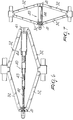
- the lowerable bicycle rack particularly for motor vehicles, recreational vehicles, vans, and the like comprises a fixed frame 2 that is advantageously constituted by two vertical uprights 3 that end with upper coupling portions 4 and lower coupling portions 5 and are mutually joined by a cross-member 6.
- Said fixed frame 2 can be fixed, in a per se known manner, to the rear part of a motor vehicle 8 and the like and is positioned so that it lies above the region affected by the registration plate and so as to avoid impairing the visibility of the rear lights of the motor vehicle.
- a movable frame 10 is connected to the fixed frame 2 and advantageously is substantially L-shaped, with a horizontal arm 11 on which runners 12 for accommodating bicycles, generally designated by the reference numeral 13, are located.
- the vertical arm of the movable frame has two outer uprights 14 that are arranged so as to correspond to the uprights 3.
- the particularity of the invention is constituted by the fact that there are linear sliding means that act between the movable frame 10 and the fixed frame 2, so as to allow a linear translatory motion of the movable frame.
- Said linear sliding means are constituted by translatory motion blocks, generally designated by the reference numeral 20, that are fixed to the outer uprights 14 and slidingly engage the uprights 3.
- the particularity is constituted by the fact that there are actuator means that act on said sliding blocks 20 so as to produce their translatory motion.
- a possible embodiment of the translatory motion actuator means which must not be interpreted in a limitative sense, is constituted by a bar with right- and left-hand threads 30 that engages corresponding sliding female threads 31 that are connected, by means of articulated linkages 32, respectively to a central body 33 that is rigidly coupled to a cross-member 34 that is connected to the translatory motion blocks 20; symmetrically, the lower articulated linkages are connected to a lower fixed central body 35 that is rigidly coupled to the fixed frame 2.
- the female threads 31 perform a translatory motion with respect to each other in one direction or in the opposite direction; in particular, when the female threads move mutually apart, the body 33 is moved toward the double-threaded bar 30 and therefore the movable frame 10 is lowered; likewise, the translatory motion of the female threads 31 toward each other causes the movable frame 10 to rise again.
- the actuator means are constituted by a telescopic strut 40 composed of threaded elements that acts between the central blocks 41 to which the linkages 32 are articulated.
- a threaded internal element 42 that is rotatably associated with a central block 41 and engages the internal thread of an externally threaded intermediate element 43 that can engage another intermediate element, again designated by the reference numeral 43, or the internal thread of an outer tubular element 44 that is internally threaded and is supported by the other block 41.
- Said actuation means can be constituted, for example, by a bar with a single thread that rotatably engages an element that is pivoted to the linkages 32 and a female thread that engages another pair of linkages; likewise, it is possible to provide cable systems, belt systems, gear systems, and the like.
- a locator 50 is provided at the lower part of the fixed frame 2 and acts as support for the movable frame 10, thus facilitating its sliding.
- the materials employed, as well as the contingent shapes and dimensions may be any according to the requirements.
Landscapes
- Engineering & Computer Science (AREA)
- Mechanical Engineering (AREA)
- Fittings On The Vehicle Exterior For Carrying Loads, And Devices For Holding Or Mounting Articles (AREA)
- Transmission Devices (AREA)
- Linear Motors (AREA)
Abstract
Description
- The present invention relates to a lowerable bicycle rack, particularly for motor vehicles, recreational vehicles, vans, and the like.
- It is known that bicycle racks installed on motor vehicles, campers, caravans, and the like can be installed at the rear part of the vehicle; when using this type of installation, the bicycle racks must be mounted in an elevated position, since according to the provisions of the current road traffic code, said bicycle racks must not cover the registration plate of the vehicle and must have a certain angle with respect to the lights of the vehicle to avoid hindering their visibility.
- The problem encountered with these types of bicycle rack arises from the fact that in order to fit the bicycles on the rack it is necessary to lift them to a certain height and therefore apply an effort that is sometimes considerable or in any case difficult for elderly or short-stature people.
- In order to try to solve this problem, solutions have already been marketed that allow to lower the structure of the bicycle rack to a lower position so as to facilitate bicycle positioning.
- However, these solutions are very complicated from a structural point of view, are very expensive, and are furthermore difficult to use in order to pass from the lowered position to the raised position.
- In particular, a conventional solution uses a fixed frame that is associated with the vehicle and a movable frame, which forms the bicycle supporting part, connected to the fixed frame by virtue of a pantograph system that allows to pass from a lowered position to a raised position and vice versa. However, with this solution it is necessary to apply considerable forces to assume the raised position; moreover, the movable frame part is subjected to a combined rotary and translatory motion that requires considerable force to perform.
- The aim of the invention is to eliminate the above described drawbacks, providing a lowerable bicycle rack particularly for motor vehicles, recreational vehicles, vans, and the like, that can assume different vertical positions without requiring particular efforts for the user.
- Within the scope of this aim, a particular object of the invention is to provide a bicycle rack in which the position can be varied without discontinuities, thus always having the possibility of selecting the optimum position.
- Another object of the present invention is to provide a bicycle rack that does not require intense efforts to move it and furthermore does not produce backward translatory motions during movement.
- Another object of the present invention is to provide a lowerable bicycle rack that can be easily obtained starting from commonly commercially available elements and materials and is furthermore competitive from a merely economic point of view.
- This aim, these objects, and others which will become apparent hereinafter are achieved by a lowerable bicycle rack particularly for motor vehicles, recreational vehicles, vans, and the like, according to the invention, which comprises a fixed frame, which can be connected to a motor vehicle and the like, and a movable frame for supporting at least one bicycle, characterized in that it comprises linear sliding means that interact between said movable frame and said fixed frame for the linear translatory motion of said movable frame.
- Further characteristics and advantages will become apparent from the description of a preferred but not exclusive embodiment of a lowerable bicycle rack particularly for motor vehicles, recreational vehicles, vans, and the like, illustrated only by way of non-limitative example in the accompanying drawings, wherein:
- figure 1 is a schematic lateral elevation view of the bicycle rack according to the invention, applied to a vehicle;
- figure 2 is a front view of the bicycle rack;
- figure 3 is a schematic perspective view of the detail of the linear sliding means that interact between the movable frame and the fixed frame;
- figure 4 is a lateral elevation view of the bicycle rack, shown in lowered position;
- figure 5 is a lateral elevational view of the bicycle rack, shown in raised position;
- figure 6 is a view of the actuator means in extended position;
- figure 7 is a view of the actuator means in retracted position.
- With reference to the above figures, the lowerable bicycle rack particularly for motor vehicles, recreational vehicles, vans, and the like, according to the invention, generally designated by the reference numeral 1, comprises a fixed
frame 2 that is advantageously constituted by twovertical uprights 3 that end withupper coupling portions 4 andlower coupling portions 5 and are mutually joined by across-member 6. - Said fixed
frame 2 can be fixed, in a per se known manner, to the rear part of amotor vehicle 8 and the like and is positioned so that it lies above the region affected by the registration plate and so as to avoid impairing the visibility of the rear lights of the motor vehicle. - A
movable frame 10 is connected to the fixedframe 2 and advantageously is substantially L-shaped, with a horizontal arm 11 on whichrunners 12 for accommodating bicycles, generally designated by thereference numeral 13, are located. - The vertical arm of the movable frame has two
outer uprights 14 that are arranged so as to correspond to theuprights 3. - The particularity of the invention is constituted by the fact that there are linear sliding means that act between the
movable frame 10 and the fixedframe 2, so as to allow a linear translatory motion of the movable frame. - Said linear sliding means are constituted by translatory motion blocks, generally designated by the
reference numeral 20, that are fixed to theouter uprights 14 and slidingly engage theuprights 3. - Furthermore, there are
lower blocks 21 that are fixed to theuprights 3 and slidingly engage theuprights 14 so as to act as guides. - The particularity is constituted by the fact that there are actuator means that act on said sliding
blocks 20 so as to produce their translatory motion. - A possible embodiment of the translatory motion actuator means, which must not be interpreted in a limitative sense, is constituted by a bar with right- and left-
hand threads 30 that engages corresponding slidingfemale threads 31 that are connected, by means of articulatedlinkages 32, respectively to a central body 33 that is rigidly coupled to a cross-member 34 that is connected to the translatory motion blocks 20; symmetrically, the lower articulated linkages are connected to a lower fixedcentral body 35 that is rigidly coupled to the fixedframe 2. - With this arrangement, by acting with an
actuation rod 40 that turns the double-threadedbar 30, thefemale threads 31 perform a translatory motion with respect to each other in one direction or in the opposite direction; in particular, when the female threads move mutually apart, the body 33 is moved toward the double-threadedbar 30 and therefore themovable frame 10 is lowered; likewise, the translatory motion of thefemale threads 31 toward each other causes themovable frame 10 to rise again. - Of course, it is possible to use other equivalent means to perform the translatory motion, without altering the concept that the particular characteristic is constituted by the fact that the
movable frame 10 moves in a linear fashion with respect to the fixedframe 2. - Thus, for example, as shown in figures 6 and 7, the actuator means are constituted by a
telescopic strut 40 composed of threaded elements that acts between thecentral blocks 41 to which thelinkages 32 are articulated. - In greater detail, there is a threaded
internal element 42 that is rotatably associated with acentral block 41 and engages the internal thread of an externally threadedintermediate element 43 that can engage another intermediate element, again designated by thereference numeral 43, or the internal thread of an outertubular element 44 that is internally threaded and is supported by theother block 41. - Said actuation means can be constituted, for example, by a bar with a single thread that rotatably engages an element that is pivoted to the
linkages 32 and a female thread that engages another pair of linkages; likewise, it is possible to provide cable systems, belt systems, gear systems, and the like. - It should be added to the above that a
locator 50 is provided at the lower part of thefixed frame 2 and acts as support for themovable frame 10, thus facilitating its sliding. - From the above description it is thus evident that the invention achieves the intended aim and objects, and in particular the fact is stressed that a lowerable bicycle rack is provided which allows to easily perform a linear translatory motion of the bicycle-supporting movable frame without causing particular constructive complexities and, most of all, providing a system that requires limited force for the translatory motion of the movable frame.
- The invention thus conceived is susceptible of numerous modifications and variations, all of which are within the scope of the inventive concept.
- All the details may furthermore be replaced with other technically equivalent elements.
- In practice, the materials employed, as well as the contingent shapes and dimensions, may be any according to the requirements.
- Where technical features mentioned in any claim are followed by reference signs, those reference signs have been included for the sole purpose of increasing the intelligibility of the claims and accordingly, such reference signs do not have any limiting effect on the interpretation of each element identified by way of example by such reference signs.
Claims (7)
- A lowerable bicycle rack particularly for motor vehicles, recreational vehicles, vans, and the like, comprising a fixed frame, which can be connected to a motor vehicle and the like, and a movable frame for supporting at least one bicycle, characterized in that it comprises linear sliding means that interact between said movable frame and said fixed frame for the linear translatory motion of said movable frame.
- A bicycle rack according to claim 1, characterized in that it comprises actuator means that act on said linear sliding means for the translatory movement of said movable frame.
- A bicycle rack according to claim 1, characterized in that said linear sliding means are constituted by translatory motion blocks that are rigidly coupled to said movable frame and can slidingly engage said fixed frame, lower blocks being furthermore provided which are rigidly coupled to said fixed frame and sliding engage said movable frame.
- A bicycle rack according to claim 2, characterized in that said actuator means are constituted by a double-threaded bar that can engage female threads that are connected, by means of articulated linkages, to an upper central body, rigidly coupled to said translatory motion block, and to a lower central body rigidly coupled to said fixed frame.
- A bicycle rack according to claim 2, characterized in that said actuator means are constituted by a telescopic strut.
- A bicycle rack according to claim 5, characterized in that said telescopic strut is constituted by a plurality of mutually interpenetrating threaded elements.
- A bicycle rack according to claim 1, characterized in that it comprises a locator that is rigidly coupled to said fixed frame and slidingly engages said movable frame.
Applications Claiming Priority (2)
| Application Number | Priority Date | Filing Date | Title |
|---|---|---|---|
| IT95MI001632A IT1277358B1 (en) | 1995-07-26 | 1995-07-26 | LOWERABLE BICYCLE RACK PARTICULARLY FOR CARS, RECREATIONAL VEHICLES, VANS AND SIMILAR |
| ITMI951632 | 1995-07-26 |
Publications (2)
| Publication Number | Publication Date |
|---|---|
| EP0755826A1 true EP0755826A1 (en) | 1997-01-29 |
| EP0755826B1 EP0755826B1 (en) | 2000-06-21 |
Family
ID=11372063
Family Applications (1)
| Application Number | Title | Priority Date | Filing Date |
|---|---|---|---|
| EP96111768A Expired - Lifetime EP0755826B1 (en) | 1995-07-26 | 1996-07-22 | Lowerable bicycle rack particularly for motor vehicles, recreational vehicles, vans and the like |
Country Status (3)
| Country | Link |
|---|---|
| EP (1) | EP0755826B1 (en) |
| DE (1) | DE69608931T2 (en) |
| IT (1) | IT1277358B1 (en) |
Cited By (3)
| Publication number | Priority date | Publication date | Assignee | Title |
|---|---|---|---|---|
| WO1998022309A1 (en) * | 1996-11-20 | 1998-05-28 | Doerr Klaus | Rear luggage carrier for vehicles |
| EP2374664A1 (en) | 2009-11-26 | 2011-10-12 | Teun Hop | Rack for transport of bicycles and the like |
| BE1021650B1 (en) * | 2013-04-11 | 2015-12-22 | Brustor, Naamloze Vennootschap | ELEVATOR FOR A BIKE OR LUGGAGE RACK |
Families Citing this family (3)
| Publication number | Priority date | Publication date | Assignee | Title |
|---|---|---|---|---|
| DE102012003629A1 (en) | 2012-02-24 | 2012-10-04 | Daimler Ag | Bicycle transport device mounted to passenger car, has actuating unit that includes lever element and actuates height adjustment mechanism which changes position of fixing unit |
| US9376063B2 (en) * | 2012-04-30 | 2016-06-28 | Yakima Products, Inc. | Vehicle carrier system |
| US12330595B1 (en) | 2019-12-18 | 2025-06-17 | Saris Equipment, Llc | Hitch-mounted lift rack for bicycles or other equipment |
Citations (5)
| Publication number | Priority date | Publication date | Assignee | Title |
|---|---|---|---|---|
| DE9013591U1 (en) * | 1990-09-27 | 1991-02-07 | Mario, Giuseppe Di, 6230 Frankfurt | Load carrier for bicycles, skis and / or luggage. |
| DE9116250U1 (en) * | 1991-11-07 | 1992-05-07 | Camping Gaz International (Deutschland) GmbH, 6234 Hattersheim | Rear luggage rack with bicycle holder for minibuses etc. |
| DE9214141U1 (en) * | 1992-10-20 | 1992-12-10 | Camping Gaz International (Deutschland) GmbH, 6234 Hattersheim | Supporting device for attachment to a substantially vertical rear wall of a vehicle, in particular a motor home or a minibus |
| DE4214567A1 (en) * | 1992-02-07 | 1993-08-12 | Tr Em S R L | Attaching bicycle carrier frame to rear of vehicle - using pair of spring loaded pins in engagement with bumper bar |
| DE9413724U1 (en) * | 1994-08-26 | 1994-11-10 | Mario, Giuseppe di, 60437 Frankfurt | Load carriers, in particular for bicycles |
-
1995
- 1995-07-26 IT IT95MI001632A patent/IT1277358B1/en active IP Right Grant
-
1996
- 1996-07-22 DE DE69608931T patent/DE69608931T2/en not_active Expired - Lifetime
- 1996-07-22 EP EP96111768A patent/EP0755826B1/en not_active Expired - Lifetime
Patent Citations (5)
| Publication number | Priority date | Publication date | Assignee | Title |
|---|---|---|---|---|
| DE9013591U1 (en) * | 1990-09-27 | 1991-02-07 | Mario, Giuseppe Di, 6230 Frankfurt | Load carrier for bicycles, skis and / or luggage. |
| DE9116250U1 (en) * | 1991-11-07 | 1992-05-07 | Camping Gaz International (Deutschland) GmbH, 6234 Hattersheim | Rear luggage rack with bicycle holder for minibuses etc. |
| DE4214567A1 (en) * | 1992-02-07 | 1993-08-12 | Tr Em S R L | Attaching bicycle carrier frame to rear of vehicle - using pair of spring loaded pins in engagement with bumper bar |
| DE9214141U1 (en) * | 1992-10-20 | 1992-12-10 | Camping Gaz International (Deutschland) GmbH, 6234 Hattersheim | Supporting device for attachment to a substantially vertical rear wall of a vehicle, in particular a motor home or a minibus |
| DE9413724U1 (en) * | 1994-08-26 | 1994-11-10 | Mario, Giuseppe di, 60437 Frankfurt | Load carriers, in particular for bicycles |
Cited By (4)
| Publication number | Priority date | Publication date | Assignee | Title |
|---|---|---|---|---|
| WO1998022309A1 (en) * | 1996-11-20 | 1998-05-28 | Doerr Klaus | Rear luggage carrier for vehicles |
| EP2374664A1 (en) | 2009-11-26 | 2011-10-12 | Teun Hop | Rack for transport of bicycles and the like |
| BE1021650B1 (en) * | 2013-04-11 | 2015-12-22 | Brustor, Naamloze Vennootschap | ELEVATOR FOR A BIKE OR LUGGAGE RACK |
| DE102014005221B4 (en) | 2013-04-11 | 2026-04-30 | Brustor, Naamloze Vennootschap | Lift for bicycle or luggage carriers |
Also Published As
| Publication number | Publication date |
|---|---|
| EP0755826B1 (en) | 2000-06-21 |
| DE69608931T2 (en) | 2000-11-30 |
| IT1277358B1 (en) | 1997-11-10 |
| DE69608931D1 (en) | 2000-07-27 |
| ITMI951632A0 (en) | 1995-07-26 |
| ITMI951632A1 (en) | 1997-01-26 |
Similar Documents
| Publication | Publication Date | Title |
|---|---|---|
| US5586802A (en) | Linkage for guiding a retractable room | |
| CA2329615C (en) | Slide-out compartment for a vehicle | |
| US6029873A (en) | Retractable roof rack | |
| US5094478A (en) | Motor vehicle having a rollover bar | |
| US4598982A (en) | Apparatus for extending rear view mirror | |
| US5857733A (en) | Synchronization device for a slide out room | |
| US5473958A (en) | Spindle drive for an adjusting mechanism for vehicle seats | |
| EP0755826A1 (en) | Lowerable bicycle rack particularly for motor vehicles, recreational vehicles, vans and the like | |
| US7413252B2 (en) | Motor vehicle seat lift assembly | |
| US20120223540A1 (en) | Recreational Vehicle Lift Mechanism | |
| EP0325380B1 (en) | A device for opening and closing the roof hatch of a vehicle | |
| US6257646B1 (en) | Sliding pivot for a truck bed cover bow | |
| WO2000050279A9 (en) | Vehicle leveling assembly | |
| JPS63291741A (en) | Front sheet for automobile | |
| US4110819A (en) | Headlight tilting control device of motor vehicle | |
| EP0666211A1 (en) | Retractable windshield | |
| US4118765A (en) | Automobile headlights | |
| CA2053790A1 (en) | Electrical jack for automotive vehicles | |
| US3608956A (en) | Top mechanism for convertible-type automobile | |
| CN216915698U (en) | Vehicle pedal | |
| US4961638A (en) | Internal rearview mirror with an adjustable support for motor vehicles | |
| KR0157262B1 (en) | Moving system of console box in car power seat | |
| US2953188A (en) | Vehicle seat | |
| JP4046232B2 (en) | Brake pedal assembly for automobile | |
| GB2303350A (en) | Retractable Step |
Legal Events
| Date | Code | Title | Description |
|---|---|---|---|
| PUAI | Public reference made under article 153(3) epc to a published international application that has entered the european phase |
Free format text: ORIGINAL CODE: 0009012 |
|
| AK | Designated contracting states |
Kind code of ref document: A1 Designated state(s): BE DE FR GB IT |
|
| 17P | Request for examination filed |
Effective date: 19970626 |
|
| 17Q | First examination report despatched |
Effective date: 19981014 |
|
| GRAG | Despatch of communication of intention to grant |
Free format text: ORIGINAL CODE: EPIDOS AGRA |
|
| GRAG | Despatch of communication of intention to grant |
Free format text: ORIGINAL CODE: EPIDOS AGRA |
|
| GRAH | Despatch of communication of intention to grant a patent |
Free format text: ORIGINAL CODE: EPIDOS IGRA |
|
| GRAH | Despatch of communication of intention to grant a patent |
Free format text: ORIGINAL CODE: EPIDOS IGRA |
|
| GRAH | Despatch of communication of intention to grant a patent |
Free format text: ORIGINAL CODE: EPIDOS IGRA |
|
| GRAA | (expected) grant |
Free format text: ORIGINAL CODE: 0009210 |
|
| AK | Designated contracting states |
Kind code of ref document: B1 Designated state(s): BE DE FR GB IT |
|
| PG25 | Lapsed in a contracting state [announced via postgrant information from national office to epo] |
Ref country code: IT Free format text: LAPSE BECAUSE OF FAILURE TO SUBMIT A TRANSLATION OF THE DESCRIPTION OR TO PAY THE FEE WITHIN THE PRESCRIBED TIME-LIMIT;WARNING: LAPSES OF ITALIAN PATENTS WITH EFFECTIVE DATE BEFORE 2007 MAY HAVE OCCURRED AT ANY TIME BEFORE 2007. THE CORRECT EFFECTIVE DATE MAY BE DIFFERENT FROM THE ONE RECORDED. Effective date: 20000621 Ref country code: FR Free format text: LAPSE BECAUSE OF FAILURE TO SUBMIT A TRANSLATION OF THE DESCRIPTION OR TO PAY THE FEE WITHIN THE PRESCRIBED TIME-LIMIT Effective date: 20000621 Ref country code: BE Free format text: LAPSE BECAUSE OF FAILURE TO SUBMIT A TRANSLATION OF THE DESCRIPTION OR TO PAY THE FEE WITHIN THE PRESCRIBED TIME-LIMIT Effective date: 20000621 |
|
| REF | Corresponds to: |
Ref document number: 69608931 Country of ref document: DE Date of ref document: 20000727 |
|
| PG25 | Lapsed in a contracting state [announced via postgrant information from national office to epo] |
Ref country code: GB Free format text: LAPSE BECAUSE OF NON-PAYMENT OF DUE FEES Effective date: 20000921 |
|
| EN | Fr: translation not filed | ||
| PLBE | No opposition filed within time limit |
Free format text: ORIGINAL CODE: 0009261 |
|
| STAA | Information on the status of an ep patent application or granted ep patent |
Free format text: STATUS: NO OPPOSITION FILED WITHIN TIME LIMIT |
|
| GBPC | Gb: european patent ceased through non-payment of renewal fee |
Effective date: 20000921 |
|
| 26N | No opposition filed | ||
| PGFP | Annual fee paid to national office [announced via postgrant information from national office to epo] |
Ref country code: DE Payment date: 20150907 Year of fee payment: 20 |
|
| REG | Reference to a national code |
Ref country code: DE Ref legal event code: R071 Ref document number: 69608931 Country of ref document: DE |