EP0754959B1 - Microéléments de balayage pour système optique - Google Patents
Microéléments de balayage pour système optique Download PDFInfo
- Publication number
- EP0754959B1 EP0754959B1 EP96401586A EP96401586A EP0754959B1 EP 0754959 B1 EP0754959 B1 EP 0754959B1 EP 96401586 A EP96401586 A EP 96401586A EP 96401586 A EP96401586 A EP 96401586A EP 0754959 B1 EP0754959 B1 EP 0754959B1
- Authority
- EP
- European Patent Office
- Prior art keywords
- membrane
- substrate
- deflection
- micro
- microoptical
- Prior art date
- Legal status (The legal status is an assumption and is not a legal conclusion. Google has not performed a legal analysis and makes no representation as to the accuracy of the status listed.)
- Expired - Lifetime
Links
Images


Classifications
-
- G—PHYSICS
- G02—OPTICS
- G02B—OPTICAL ELEMENTS, SYSTEMS OR APPARATUS
- G02B26/00—Optical devices or arrangements for the control of light using movable or deformable optical elements
- G02B26/08—Optical devices or arrangements for the control of light using movable or deformable optical elements for controlling the direction of light
- G02B26/0816—Optical devices or arrangements for the control of light using movable or deformable optical elements for controlling the direction of light by means of one or more reflecting elements
- G02B26/0833—Optical devices or arrangements for the control of light using movable or deformable optical elements for controlling the direction of light by means of one or more reflecting elements the reflecting element being a micromechanical device, e.g. a MEMS mirror, DMD
- G02B26/0858—Optical devices or arrangements for the control of light using movable or deformable optical elements for controlling the direction of light by means of one or more reflecting elements the reflecting element being a micromechanical device, e.g. a MEMS mirror, DMD the reflecting means being moved or deformed by piezoelectric means
Definitions
- the present invention relates to the field of scanning microelements for optical system, especially the micromiroirs orientable for system optomechanical and their methods of realization.
- Such components find their application in miniaturized optical systems that need is felt in many applications, particularly in the automotive, medical or the field of industrial control.
- One of the key elements of these microsystems is the scanning element of beams of light, the realization of which particular difficulties as soon as the angles of deflection sought exceed a few degrees.
- a first known device is described in a Article by M.A. Mignardi entitled “Digital micromirror array for projection TV ", released in Solide State Technology, pages 63-68, July 1994.
- This device is shown schematically in FIG. micromirror 2 which has a superior surface reflective and that also plays the role of upper electrode compared to two electrodes lower 6, 8 deposited on a substrate 10. Playing on the tensions applied between the different electrodes, it is possible to subject the mirror 2 a deflection movement around a beam of twist 4. This causes the deflection of a beam incident 7 of an angle ⁇ between about + 10 ° and -10 °.
- Micromechanical Light Deflector Array (IBM Technical Disclosure Bulletin, Vol 20, No. 1, June 1977) describes a microelement for optical system.
- the object of the invention is first of all to propose a new type of scanning microelements for optical system, compatible with collective manufacturing.
- This element is fully compatible with collective manufacturing techniques known in the field of microelectronics.
- the part of the membrane located above of the cavity can undergo a subsequent deflection minus a second direction above the cavity.
- the amplitude along one of the directions of deflection can then be greater than the amplitude following one of the other deflection directions.
- the part of the membrane that can undergo deflection can be connected by a microbeam to a fixed part which provides the means to deflection to the moving part.
- the fixed part can then have an axis of symmetry with respect to which the microbeam is parallel.
- the latter can be offset from to this axis.
- the mobile part of the membrane can be offset laterally with respect to the axis of symmetry of the fixed part.
- the means to a deflection to the moving part may include several groups of resources distributed on both sides of the axis of symmetry.
- the deflection means may be of the type piezoelectric or electrostatic.
- the part of the membrane that can deflect can be oriented according to a plan crystallographic structure of the substrate.
- the cavity can be located on the edge of a opening opening made in the substrate, this opening opening can possibly be a opening through the entire thickness of the substrate.
- a microoptic device can moreover have a microelement as described above, associated with a second reflective zone arranged on the substrate so as to reflect, towards the reflective area of the membrane, a beam light, called incoming beam, coming from a certain direction, this one then undergoing two successive reflections to then form a beam outgoing.
- the second reflective zone is arranged on the substrate: it can be carried out directly on the substrate, or it can be reported on this one.
- This second reflective zone can be formed by or on a wall of an opening opening or through practiced in the substrate.
- This wall can also be oriented according to a plan crystallographic structure of the substrate.
- a microoptical device allows solve the problem of assembling wafers entire components. Indeed, beyond the collective fabrication of the components involved in a microsystem, it is desirable, in particular for cost reasons, that their assembly can also be done at the level of whole platelets and not just elements individual. In addition, it is important that the architecture of the different components to assemble in the easiest way possible stack. For such a stacking is possible with microscan elements or devices of microoptics incorporating such elements, it is desirable that the deflection of the light beam be make it to the front of the device, not to the back, that is to say that the angle defined by a beam entering the device and a beam out of the device is greater than 90 °.
- a device for microoptical as described above may furthermore be characterized in that the second zone reflective is arranged so that the incoming beam and the outgoing beam make between they an angle greater than 90 °.
- the two reflective zones can define two substantially parallel planes when the membrane is in the rest position. These two plans can be parallel to a given crystallographic plane of the substrate.
- FIG. 2 is a first example of embodiment of a device according to the invention.
- Sure this figure reference 12 designates a substrate, a insulating or semiconductor material, for example a silicon substrate.
- a cavity 18 has been opened in this substrate.
- a preliminary deposit of a membrane 14, 16 in a dielectric material was made on the surface 15 of the substrate.
- the opening of the cavity 18a allowed to release part of the membrane, particular part 14.
- the latter is preferably treated, for example by a coating 20, to form a reflective zone (called also mirror in the rest of the description) for a certain range of wavelengths.
- the end 14 of the membrane, on which is located at least a part of the reflective zone is mobile.
- FIG. 2 means piezoelectric, having a lower electrode 22, disposed over the membrane 16, a layer 24 of a piezoelectric material and an electrode 26. Means 28 are furthermore provided for establish between the electrodes 26 and 22 the voltage desired.
- the layer of piezoelectric material can be ZnO, CdS, AlN or a material ferroelectric, deposited in the form of thin layers.
- the excitation mode in elongation can be put into play with fairly small thicknesses of material piezoelectric, which allows to realize a compact device.
- the mode of excitation in bending requires a thickness of material more important piezoelectric, but returns nonetheless in the context of the present invention.
- the excitation force imposed by the piezoelectric material on the membrane is directed following the arrow F 'presented in broken lines on Figure 2, while in the case of the mode of excitation in elongation, the excitation force is the force F shown in solid lines in FIG.
- the mode of excitation in flexion or elongation depends on the orientation crystal of the piezoelectric material and its geometry, and, in particular, its thickness e.
- FIG. 3 Another solution to achieve a means of deflection of the membrane is to make a command electrostatic electrode facing.
- a command electrostatic electrode facing Such device is illustrated in Figure 3 where numerical references identical to those in the figure 2 denote the same elements.
- Reference 30 designates a first electrode, on the surface of the substrate 12, the reference 32 designates a second electrode located under the membrane 16 and on a substrate 34, which does not rest directly on the upper face of the substrate 12, but is separated by a spacing 36 obtained by removal of a layer of material on the surface of 12.
- the application to the electrodes 30, 32 of a certain tension allows them to be brought closer together or move away from each other, and get a movement corresponding to the membrane 14, 16.
- the electrode 30 can be obtained by ion implantation boron, to form silica, and the substrate 34 may be a thin layer of silicon.
- the solution of making a command electrostatic requires a succession of steps technologies probably a little more complex than in the case of a piezoelectric control but removes obviously the use of this piezoelectric material which is always difficult to achieve.
- the membrane of dielectric material may have various forms. In FIGS. 2 and 3 the membrane actually defines two plans doing between them, in particularly when the membrane is at rest, an angle ⁇ greater than or greater than 90 °.
- the reflective zone 20, or part of the reflective zone 20 is located, or is deposited on the (mobile) part of the membrane which makes an angle ⁇ with the surface 15 of the substrate on which a part fixed membrane is achieved.
- a reflector according to the invention can be achieved, in a general way, by giving the angle ⁇ has any value.
- an angle ⁇ such as part 14 of the membrane is directed according to a plane crystallographic substrate 12 may be preferred.
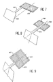
- a membrane, without its substrate, is shown in perspective in Figure 4, the reference 38 designating the deflection means of the membrane, for example electrostatic means such that they have been described above in connection with the FIG. 3.
- the membrane has a constant width following a axis Oz, the only possibility of actuation then being bending around the Oz axis.
- a beam configuration such as that of FIG. 5, associated with a single pair of electrodes (or a single piezoelectric crystal) having the same axis of symmetry xx 'in the plane of the plate allows an excitation of the mode of bending (corresponding to ⁇ f in Figure 5), but is rather poorly adapted to excite the torsion mode (corresponding to ⁇ t ). It is therefore preferable to adapt the geometry of the device, in particular the position of the beam and the arrangement of the elements of the excitation system, to the type of mode that it is desired to excite.
- a solution, to get a good excitement two modes of bending and twisting may consist of as shown in Figure 6, to use a beam geometry unsymmetrical with respect to the axis xx ', the excitation zone being able to remain unique and symmetrical with respect to this same axis.
- the configuration of Figure 6 shows an asymmetry, but this one is in fact still not very marked.
- Figure 7 where, by relative to the axis xx 'and to the excitation device 50, the beam 48 and the mirror 52 are deported to the maximum to the right, that is to say in the direction z '.
- FIG 8 Another solution, to be able to excite simultaneously torsion and bending modes, is illustrated in Figure 8 and consists in using a excitation configuration with multiple groups excitation means, (several pairs of electrodes or more piezoelectric crystals) that allow to modify, by a suitable addressing, for example pairs of electrodes or crystals piezoelectric devices involved, the mode of excitation of the beam 54.
- groups excitation means in the form of two pairs of electrodes 56, 58 for an excitation of the type electrostatic: both pairs of electrodes can be addressed, in phase and / or in phase opposition according to the preferred mechanical vibration mode, by the use of excitation frequencies generally different.
- a neighboring configuration, three pairs of electrodes 60, 62, 64 also allows to create the desired asymmetry, as shown in Figure 9.
- a beam 66 connects an excitation zone 68 to a mirror zone 70, the latter having, in its upper part, a recess 72 which will promote the torsion movement.
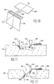
- FIG. 11 Another embodiment of the invention is illustrated in Figure 11.
- a membrane 78 in one dielectric material with its actuating element 80 are deposited on a substrate 76.
- the invention a part of the membrane, presenting a reflective area 77 may be deflected over a cavity 82 made in the substrate 76.
- another opening 74 leading to the substrate surface 76 is practiced in the latter.
- a zone reflective for example a fixed micromirror 84, can be realized, which allows for example to reflect an incident or incoming beam 85 in one direction 87 towards the reflective zone 77 of the membrane.
- the latter will reflect the beam 87 in a direction 89 (outgoing beam), the stretched bending movements or twisting of the membrane to vary the direction of the outgoing beam 89.
- a through hole 90 is formed in the substrate 88.
- a membrane, its excitation element and the cavity are designated respectively by references 94, 96, 92.
- This micromirror can be arranged in such a way that incoming beam 99 is reflected in the form of a beam 101 to the membrane 94, the surface reflective of the latter resulting in a second deviation to form an outgoing beam 103.
- the incoming beam 99 and the outgoing beam 103 make between them an angle close to 180 ° in any case greater than 90 °, which is not the case with the configuration shown in Figure 11 where the angle between the incoming and outgoing beams is close to 0 °.
- the reflective zone 95 of the membrane and the reflective zone 98 form two parallel or substantially parallel planes, by example when the membrane 94 is at rest. In the case of a silicon substrate 88, this result can be obtained by choosing for these two plans a plan crystallographic (plane 1,1,1 or 1, -1,1).
- the device of FIG. 12 makes it possible to obtain a direction of the beam coming out about the same or in any case very close to the direction of the beam incident. In devices with a single mirror this condition could only be achieved by grazing incidence, which poses delicate problems of geometry and alignment.
- FIG 13 Another variant is illustrated in the figure 13. It also provides a direction of the outgoing beam 103 almost identical to, or in any very similar case of, the direction of the incident beam 102. It implements two scanning microelements according to the invention, each made on one side of a substrate, the two microelements being "head "Again, a through hole 90 is practiced in the substrate 88, or separates the two microelements sweep.
- a first element comprises a membrane 94 and its excitation element 96 over a cavity 92.
- a second microelement is made on a another surface of the substrate 88, which comprises a second cavity 93.
- This microelement essentially comprises a membrane 97, excitation means 100 (of the type piezoelectric or electrostatic, as already described above).
- the membrane 97 defines two planes forming between them an angle ⁇ no zero, preferably greater than 90 °, for example included between 90 ° and 135 ° or between 120 ° and 130 °.
- the moving part of the second membrane 97 may undergo a deflection according to minus a first direction "above” (in the figure 13, in fact, below), or in relation to, the cavity 93 made in the substrate 88.
- a component has two microelements of scanning on the same side of the substrate (even relative configuration of the two mirrors as that of the Figure 11).
- the first membrane can have one of the structures that have been described above, for example in connection with Figures 5 to 10, while the second membrane can also have any of the structures described above, in particular in connection with FIGS. 5 to 10.
- membrane can be flexed around the axis Oz (see notation in Figure 5) but also in twist around the Oy axis.
- one of the membranes can be activated by means piezoelectric, while the other is activated by electrostatic means.
- Such a device allows to amplify the accessible angle dynamics, since not only a sequential deflection of the membranes, but also a simultaneous deflection, are possible.
- one of the two mirrors can provide the deflection in one direction (for example with a control frequency f 1 ), while the second mirror deflects on another direction (control frequency f 2 ), the geometry of the control means of each mirror being of course adapted to this mode of operation.
- first and second reflective zones being arranged so that that a light beam, called incoming beam, coming from a certain direction, undergoes a first reflection on one of the two zones reflective, and a second reflection on the other reflective zone, to form an outgoing beam.
- the two reflective zones made on the mobile ends of the membranes, can be oriented in the same crystallographic plane of substrate. They can define two parallel planes or substantially parallel when the moving part of each membrane, having a reflective zone, is in the rest position: both planes can be for example parallel to a crystallographic plane given substrate.
- the formation of the cavity can be realized by reactive ionic attack microwave.
- the cavity can be located on the edge of a opening opening at the surface of the substrate on which the membrane is deposited, or even cross this substrate.
- This opening can be achieved for example by preferential chemical etching. So we can clear walls oriented according to plans crystallographic.
- the membrane can be optionally etched to make openings.
- a double-sided masking of a substrate 104 made of silicon is a double-sided masking of a substrate 104 made of silicon.
- This masking can for example track the plans 1,1,1 on the surface plane 1,0,0 of the substrate in silicon.
- Masks present respectively openings 108 and 110, the dimensions A (following a direction perpendicular to the plane of FIG. 14) and B (see Figure 14) depend on the geometry desired. In practice, if we consider silicon thickness of the order of 500 ⁇ m, it can choose A of the order of 500 to 1500 ⁇ m, depending on the section of the light beam to deflect. B may have dimensions of the same order. Of course, he is always possible to choose silicon wafers thicker (from 1 to 2 mm) and to increase the dimensions. In addition, openings 108 and 110 not necessarily the same dimensions.
- an etching is performed preferential chemical silicon (double-sided) this which leads to the formation of an opening 114 which crosses the substrate 104.
- This method of engraving is based on the difference in engraving speed between different planes crystallographic data of the same material for some attacking agents.
- the attack speed is very slow following one of the crystalline planes (the plans of type (111) for example) and very fast following the others.
- the preferential attack makes it possible to clear walls 116, 118, 120, 122 oriented along crystallographic planes, such as plans 1,1,1 or 1, -1.1. These plans then form with the vertical a angle ⁇ of about 36 °.
- the structure represented on the FIG. 15 is symmetrical with respect to a median plane contained in the silicon wafer 104 and whose trace is shown in Figure 15 by the axis xx '. It is also possible, and in some cases preferably, to achieve an asymmetrical structure, for example by playing on the dimensions of the openings masks. Such a structure is illustrated on the Figure 16, where the opening 124 presents, in its part lower, walls 128, 130 extending over one great distance that the walls 126, 132 in the part higher.
- a deposit a layer 134, 136 of thick silica is produced, for example by PECVD.
- This silica layer is going constitute the body of the mobile membrane.
- the deposit is made only on the upper face of the substrate 104. Its thickness depends of course on the desired rigidity. In practice, layers of 4 to 40 ⁇ m are used thick.
- the openings are represented symmetrically with respect to a plane perpendicular to the silicon substrate and whose trace is shown in Figure 18, by the axis YY '. In fact, it is possible to give these openings a any shape.
- the dimensions such as dimensions C, D, F, G (see Figure 18) can be defined in any way. In practice, these dimensions are of the order of a hundred or so several hundred micrometers.
- Masks used for etching the layer 136 can be simple metal masks placed on this layer.
- a fifth step will enable the production, in the substrate 104, of a cavity 144 (see FIG. 19) by isotropic etching of the silicon from the openings 140, 142 made in the layer 136 of silica.
- the technique used is preferably microwave reactive ion etching, using, for example, SF 6 . This type of ionic attack has a very high selectivity between silicon and silica.
- the membrane 138, 136 can therefore be separated from the silicon substrate 104 without the silica layer 136, 138 constituting this membrane being significantly affected.
- the thicknesses of etched silicon being of the order of 300 ⁇ m (slightly greater than half the thickness of the silicon wafers) and the selectivity being greater than 100, the silica layer is affected only very weakly. by etching (only on a thickness of about 2 to 3 ⁇ m).
- the etching geometries obtained from the openings 140, 142 made in the silica mask are approximately known as soon as the dimensions of these openings exceed a hundred microns.
- the depth of attack d (t) is equal to the product of the attack speed by the etching time and is approximately the same in all the directions of etching, starting from edges of the openings 140, 142.
- broken lines 143-1,... 143-5 represent the evolution of the attack zone at different times t 1 , t 2 , t 3 , t 4 , t 5 .
- the leading edge reaches at least the point K, which marks the lower limit of the zone 138.
- This supergrafting is not a problem considering the role of barrier layer played by silica (effect of selectivity between silica and silicon).
- the thickness E of silicon remaining at the bottom of the substrate will be relatively small, generally less than half a thickness of the substrate. In order to increase the mechanical strength of the latter, and therefore of the entire device, it may be advantageous to use an asymmetrical geometry, like that of FIG. 16, which makes it possible to keep values of E more important.
- a layer 152, 154, 156, 158 of a material making it possible to increase the reflectivity of the mirrors for example a metal deposition (Ti, Au Al, Pt, Cr) or a dielectric multilayer deposition (SiO 2 -TiO 2 ).
- This deposition step of a reflective layer may possibly be performed at the same time as the deposition steps of the electrodes 146, 150, if the metallic deposits involved are identical.
- the resulting structure is ultimately that of the FIG. 20.
- the membrane 138 is separated from the silicon substrate, but it still remains to achieve a lateral decoupling step. This can be done sawing the entire thickness of the substrate; in this In this case, the microbay elements are individualized and the collective treatment is stopped at this stage.
- the lateral decoupling can also be performed by side sawing to a slight thickness greater than half of the silicon wafer, by example before assembling a wafer containing the microbalay elements with other platelets from the device to be realized, the individualisation of devices occurring after assembly. Considering of the fragility of the membranes, it can be favorable to stiffen structures before sawing, using curable resin that can be dissolved by the following.
- the steps described above are suitable for the realization of a device with means piezoelectric actuator.
- a part of the steps described above are identical: these are particularly those that lead to the realization of the double mirrors and the membrane mobile.
- the big difference comes from the realization electrostatic control, before the filing of the silica layer 136.
- the support structure used to achieve electrostatic control is a SIMOX structure obtained by oxygen implantation, then annealing appropriately, in order to achieve a layer of buried insulating silica.
- the interest of this structure, in the case of an electrostatic control, is it allows to realize, by localized ablation of the layer of buried silica, a very fine interelectrode space (on the order of 0.2 to 0.3 ⁇ m) and very uniform. This allows, among other things, to minimize the tensions of control necessary for the mechanical excitation of the membrane comprising the movable mirror.
- the masks usable for electrode formation can be obtained by lithography techniques classic, or they are mechanical masks.
- Localized dissolution of the buried silica layer is then carried out.
- This dissolution is carried out by chemical etching (for example a traditional etching source based on hydrofluoric acid) through one or more openings made in the superficial silicon layer 162.
- a covering deposit for example Si 3 N 4 obtained in CVD.
- the masks, the surface silicon layer and the buried silica layer are eliminated in the zones complementary to the control zones.
- Metal deposits allow contacting of the lower and upper electrodes.
- the structure of localized control zones represented in FIG. 21C is obtained, the doping zone 170 constituting the lower electrode and the superficial silica layer 163, separated from this doping zone by a gap 174, serving as support for FIG. upper electrode 172.
- the contacts are not shown in this figure.
- the implementation method that can be implemented is derived from the process described above.
- the latter is a “single-sided” process in that a membrane “mobile”, capable of undergoing deflection at least a direction above a cavity practiced in the substrate, is made only on one side of this substrate.
- a "double-sided” process that leads to device according to Figure 13, can also be realized.
- deposits of silica layers thick for example by PECVD, can be realized on both sides of the substrate, these silica layers constituting the bodies of mobile membranes.
- the thickness of the layers depends on the rigidity desired, layers of 4 to 40 ⁇ m thick being in practice used.
- the invention thus makes it possible to microelement scanning, which can itself enter the realization of a microoptic component allowing to deflect a beam "forward": the direction the outgoing beam is about the same, or any case very close, to the direction of the beam incident. So, we can assemble, in cascade, different components thus produced. An assembly in cascade of two components is shown schematically in Figure 23. The surfaces of the two substrates are symbolized by broken lines.
- An incoming beam meets a first mirror 188 and is deviated to a second mirror 186; it comes out from the first component to a first mirror 190 of a second component which deviates it, by reflection, to a second mirror 192 of the second component.
- the outgoing beam has the same direction as the beam incident: this condition is particularly realized for a couple of parallel mirrors, or almost parallels, as in the case described above in connection with Figure 12.
- the angle ⁇ between the plane of the substrate (s) and each mirror is then chosen so as to have a value compatible with the desired function and a practical use of the device.
- Figure 22 schematically represents two reflective surfaces 180, 182, each forming a angle ⁇ with one of the surfaces of the substrate. (These surfaces are represented schematically by broken lines).
- An incident beam 184 encounters the reflective surface 182 at the point O, and is reflected towards the reflecting surface 180 he meets at point O '.
- An Oxy landmark is defined by the incident beam 184.
- the beam reflected by the surface 182 makes with the axis Oy an angle s.
- ⁇ is approximately equal to 125 ° (angle between the planes (1,1,1) and (1,0,0) of the silicon crystal): this value meets the criteria above.
Description
- un substrat
- une membrane en un matériau diélectrique déposé sur une surface du substrat, la membrane définissant deux plans faisant entre eux un angle α non nul, une partie de la membrane présentant une zone réfléchissante et pouvant subir une déflexion selon au moins une première direction, au-dessus d'une cavité pratiquée dans le substrat,
- des moyens pour faire subir à cette partie de la membrane une déflexion selon au moins une direction,
- un substrat,
- une première membrane en un matériau diélectrique déposée sur une première surface du substrat, la membrane définissant deux plans faisant entre eux un angle α non nul, une partie de la première membrane présentant une première zone réfléchissante, et pouvant subir une déflexion selon au moins une première direction par rapport à une première cavité pratiquée dans le substrat,
- des premiers moyens pour faire subir à cette partie de la première membrane une déflexion selon au moins la première direction,
- une deuxième membrane en un matériau diélectrique déposée sur une deuxième surface du substrat, la membrane définissant deux plans faisant entre eux un angle β non nul, une partie de la deuxième membrane présentant une deuxième zone réfléchissante, et pouvant subir une déflexion selon au moins une deuxième direction par rapport à une deuxième cavité pratiquée dans le substrat,
- des deuxièmes moyens pour faire subir à cette partie de la deuxième membrane une déflexion selon au moins la deuxième direction,
- des moyens pour faire subir à ladite partie de la première membrane une déflexion selon au moins une direction différente de la première direction, et
- des moyens pour faire subir à ladite partie de la deuxième membrane une déflexion selon au moins une direction différente de la deuxième direction.
- la figure 1 représente un dispositif selon l'art antérieur,
- les figures 2 et 3 sont des modes de réalisation de l'invention,
- les figures 4 à 10 représentent diverses formes de membrane vibrante,
- les figures 11, 12 et 13 représentent trois exemples de dispositif comportant un élément selon l'invention,
- les figures 14 à 21 représentent des étapes de réalisation de microéléments selon l'invention
- la figure 22 représente schématiquement deux surfaces réfléchissantes dans un dispositif selon l'invention
- la figure 23 représente deux composants selon l'invention, en cascade.
- une étape de dépôt, sur une surface d'un substrat, d'une membrane en un matériau diélectrique,
- une étape de formation d'une cavité dans le substrat, une partie de la membrane, qui présente une zone réfléchissante, pouvant subir une déflexion selon au moins une première direction au-dessus de cette cavité,
- une étape de formation de moyens pour faire subir à cette partie de la membrane une déflexion selon au moins une direction.
- de réaliser ultérieurement l'attaque du substrat 104 afin d'ouvrir une cavité sous la membrane et de la libérer partiellement,
- de définir une poutre reliant la partie mobile de la membrane à la zone de commande des mouvements de cette membrane (comme les poutres 40, 48, 54 sur les figures 5, 7, 8).
- de réaliser ensuite l'attaque du substrat, de chaque côté, afin d'ouvrir une cavité sous chaque membrane, et de libérer partiellement celle-ci,
- de définir, pour chaque membrane, une poutre reliant la partie mobile de celle-ci à la zone de commande des mouvements de cette membrane.
Claims (32)
- Microélément de balayage pour système optique, comprenant :caractérisé en ce qu'il comprend des moyens (40, 48, 54) pour faire subir à ladite partie de la membrane une déflexion selon au moins une deuxième direction différente de la première direction.un substrat (12, 76, 88),une membrane (14, 16, 77, 78, 94, 95) en un matériau diélectrique déposée sur une surface du substrat, la membrane définissant deux plans faisant entre eux un angle α non nul, une partie (14, 77, 95) de la membrane présentant une zone réfléchissante (20), et pouvant subir une déflexion selon au moins une première direction au-dessus d'une cavité (18, 82, 92) pratiquée dans le substrat,des moyens (22, 24, 26 ; 30, 32 ; 80,96) pour faire subir à ladite partie de la membrane une déflexion selon au moins la première direction,
- Microélément de balayage selon la revendication 1, l'angle α étant compris entre 90° et 135°.
- Microélément de balayage selon la revendication 1, l'angle α étant compris entre 120° et 130°.
- Microélément de balayage selon l'une quelconque des revendications précédentes, l'amplitude suivant une des directions de déflexion étant supérieure à l'amplitude suivant une des autres directions de déflexion.
- Microélément de balayage selon l'une quelconque des revendications précédentes, la partie de la membrane pouvant subir une déflexion étant reliée, par une micropoutre (40, 48, 54, 66), à une partie fixe qui porte les moyens pour faire subir une déflexion à la partie mobile.
- Microélément de balayage selon la revendication 5, la partie fixe présentant un axe de symétrie (xx') par rapport auquel la micropoutre est parallèle.
- Microélément de balayage selon la revendication 6, la micropoutre étant décalée par rapport à cet axe.
- Microélément de balayage selon une des revendications 6 ou 7, la partie mobile étant décalée latéralement par rapport à l'axe de symétrie de la partie fixe.
- Microélément de balayage selon une des revendications 6 à 8, les moyens pour faire subir une déflexion à la partie mobile comportant plusieurs groupes de moyens pour faire subir une déflexion, répartis de part et d'autre de l'axe de symétrie.
- Microélément de balayage selon l'une des revendications 1 à 9, les moyens pour faire subir une déflexion étant du type piézoélectrique ou électrostatique.
- Microélément de balayage selon l'une des revendications 1 à 10, la partie de la membrane pouvant subir une déflexion étant orientée suivant un plan cristallographique du substrat.
- Microélément de balayage selon l'une des revendications 1 à 11, la cavité étant située au bord d'une ouverture (74,90) débouchant à la surface du substrat sur laquelle la membrane est déposée.
- Microélément de balayage selon la revendication 12, l'ouverture débouchante (90) étant une ouverture traversant le substrat (88).
- Dispositif de microoptique comportant :un microélément de balayage selon l'une des revendications 1 à 13,une seconde zone réfléchissante (84, 98) disposée sur le substrat de manière à réfléchir, en direction de la zone réfléchissante de la membrane, un faisceau lumineux, dit faisceau entrant (85, 99), provenant d'une certaine direction, ce faisceau entrant subissant alors deux réflexions successives pour former un faisceau sortant (89, 103).
- Dispositif de microoptique selon l'une des revendications 12 ou 13 et selon la revendication 14, la seconde zone réfléchissante étant formée par ou sur une paroi de l'ouverture débouchante ou traversante pratiquée dans le substrat.
- Dispositif de microoptique selon la revendication 15, la paroi de l'ouverture sur laquelle la deuxième zone réfléchissante est formée étant orientée suivant un plan cristallographique du substrat.
- Dispositif de microoptique selon l'une des revendications 14 à 16, la seconde zone réfléchissante étant disposée de façon à ce que le faisceau entrant et le faisceau sortant fassent entre eux un angle supérieur à 90°.
- Dispositif de microoptique selon l'une des revendications 14 à 17, les deux zones réfléchissantes (95, 98) définissant deux plans sensiblement parallèles lorsque la partie de la membrane présentant une zone réfléchissante est en position de repos.
- Dispositif de microoptique selon la revendication 18, les deux plans étant parallèles à un plan cristallographique donné du substrat.
- Dispositif de microoptique, comportant :caractérisé en ce que le dispositif comprend :un substrat (88),une première membrane (94) en un matériau diélectrique déposée sur une première surface du substrat, la membrane définissant deux plans faisant entre eux un angle α non nul, une partie (95) de la première membrane présentant une première zone réfléchissante, et pouvant subir une déflexion selon au moins une première direction par rapport à une première cavité (92) pratiquée dans le substrat,des premiers moyens (96) pour faire subir à cette partie de la première membrane une déflexion selon au moins la première direction,une deuxième membrane (91) en un matériau diélectrique déposée sur une deuxième surface du substrat, la membrane définissant deux plans faisant entre eux un angle β non nul, une partie (97) de la deuxième membrane présentant une deuxième zone réfléchissante, et pouvant subir une déflexion selon au moins une deuxième direction par rapport à une deuxième cavité pratiquée dans le substrat,des deuxièmes moyens (100) pour faire subir à cette partie de la deuxième membrane une déflexion selon au moins la deuxième direction,des moyens pour faire subir à ladite partie (95) de la première membrane une déflexion selon au moins une direction différente de la première direction, etdes moyens pour faire subir à ladite partie (97) de la deuxième membrane une déflexion selon au moins une direction différente de la deuxième direction.
- Dispositif de microoptique selon la revendication 20, les première et deuxième surfaces du substrat étant situées d'un même côté par rapport au substrat, les deux cavités étant situées au bord d'une ouverture débouchant sur cette surface du substrat.
- Dispositif de microoptique selon la revendication 20, les première et deuxième surfaces du substrat étant situées sur des côtés opposés du substrat, les cavités (92, 93) étant situées au bord d'une ouverture (90) traversant le substrat.
- Dispositif de microoptique selon l'une des revendications 20 à 22, les angles α et β étant compris entre 90° et 135°.
- Dispositif de microoptique selon l'une des revendications 20 à 22, les angles α et β étant compris entre 120° et 130°.
- Dispositif de microoptique selon l'une quelconque des revendications 20 à 24, l'amplitude suivant une des directions de déflexion étant supérieure à l'amplitude suivant une des autres directions de déflexion.
- Dispositif de microoptique selon l'une des revendications 20 à 25, la partie de l'une et/ou de l'autre membrane qui peut subir une déflexion étant reliée, par une micropoutre, à une partie fixe qui porte les moyens pour faire subir une déflexion à la partie mobile.
- Dispositif de microoptique selon la revendication 26, la partie fixe présentant un axe de symétrie par rapport auquel la micropoutre est parallèle.
- Dispositif de microoptique selon la revendication 27, la micropoutre étant décalée par rapport à cet axe.
- Dispositif de microoptique selon l'une des revendications 27 ou 28, la partie mobile étant décalée latéralement par rapport à l'axe de symétrie de la partie fixe.
- Dispositif de microoptique selon l'une des revendications 27 à 29, les moyens pour faire subir une déflexion à la partie mobile comportant plusieurs groupes de moyens pour faire subir une déflexion, répartie de part et d'autre de l'axe de symétrie.
- Dispositif de microoptique selon l'une des revendications 20 à 30, les premier et second moyens pour faire subir une déflexion étant du type piézoélectrique ou électrostatique.
- Dispositif de microoptique comportant deux dispositifs de microoptique, chacun selon l'une des revendications 14 à 31, disposés en cascade, le faisceau sortant d'un des microdispositifs étant un faisceau entrant pour l'autre microdispositif.
Applications Claiming Priority (2)
| Application Number | Priority Date | Filing Date | Title |
|---|---|---|---|
| FR9508751 | 1995-07-19 | ||
| FR9508751A FR2737019B1 (fr) | 1995-07-19 | 1995-07-19 | Microelements de balayage pour systeme optique |
Publications (2)
| Publication Number | Publication Date |
|---|---|
| EP0754959A1 EP0754959A1 (fr) | 1997-01-22 |
| EP0754959B1 true EP0754959B1 (fr) | 2004-06-02 |
Family
ID=9481150
Family Applications (1)
| Application Number | Title | Priority Date | Filing Date |
|---|---|---|---|
| EP96401586A Expired - Lifetime EP0754959B1 (fr) | 1995-07-19 | 1996-07-17 | Microéléments de balayage pour système optique |
Country Status (5)
| Country | Link |
|---|---|
| US (1) | US5818623A (fr) |
| EP (1) | EP0754959B1 (fr) |
| JP (1) | JPH0933828A (fr) |
| DE (1) | DE69632611T2 (fr) |
| FR (1) | FR2737019B1 (fr) |
Families Citing this family (8)
| Publication number | Priority date | Publication date | Assignee | Title |
|---|---|---|---|---|
| US6392775B1 (en) | 1998-01-13 | 2002-05-21 | Seagate Technology Llc | Optical reflector for micro-machined mirrors |
| US6206290B1 (en) * | 1998-03-06 | 2001-03-27 | Symbol Technologies, Inc. | Control system for oscillating optical element in scanners |
| US6647164B1 (en) | 2000-10-31 | 2003-11-11 | 3M Innovative Properties Company | Gimbaled micro-mirror positionable by thermal actuators |
| US6711318B2 (en) | 2001-01-29 | 2004-03-23 | 3M Innovative Properties Company | Optical switch based on rotating vertical micro-mirror |
| US6624549B2 (en) * | 2001-03-02 | 2003-09-23 | Ngk Insulators, Ltd. | Piezoelectric/electrostrictive device and method of fabricating the same |
| JP3755460B2 (ja) * | 2001-12-26 | 2006-03-15 | ソニー株式会社 | 静電駆動型mems素子とその製造方法、光学mems素子、光変調素子、glvデバイス、レーザディスプレイ、及びmems装置 |
| WO2005119313A2 (fr) * | 2004-05-29 | 2005-12-15 | Polatis Ltd | Commutateurs optiques et actionneurs |
| FR2930457B1 (fr) * | 2008-04-24 | 2010-06-25 | Commissariat Energie Atomique | Procede de fabrication de microcanaux reconfigurables |
Family Cites Families (3)
| Publication number | Priority date | Publication date | Assignee | Title |
|---|---|---|---|---|
| US5625483A (en) * | 1990-05-29 | 1997-04-29 | Symbol Technologies, Inc. | Integrated light source and scanning element implemented on a semiconductor or electro-optical substrate |
| US5281887A (en) * | 1992-06-15 | 1994-01-25 | Engle Craig D | Two independent spatial variable degree of freedom wavefront modulator |
| EP0614101A3 (fr) * | 1993-02-03 | 1994-10-19 | Canon Kk | Déflecteur optique et méthode de sa fabrication. |
-
1995
- 1995-07-19 FR FR9508751A patent/FR2737019B1/fr not_active Expired - Fee Related
-
1996
- 1996-07-10 US US08/679,754 patent/US5818623A/en not_active Expired - Fee Related
- 1996-07-17 EP EP96401586A patent/EP0754959B1/fr not_active Expired - Lifetime
- 1996-07-17 DE DE69632611T patent/DE69632611T2/de not_active Expired - Fee Related
- 1996-07-18 JP JP8189523A patent/JPH0933828A/ja active Pending
Also Published As
| Publication number | Publication date |
|---|---|
| US5818623A (en) | 1998-10-06 |
| FR2737019B1 (fr) | 1997-08-22 |
| EP0754959A1 (fr) | 1997-01-22 |
| FR2737019A1 (fr) | 1997-01-24 |
| DE69632611T2 (de) | 2005-06-09 |
| JPH0933828A (ja) | 1997-02-07 |
| DE69632611D1 (de) | 2004-07-08 |
Similar Documents
| Publication | Publication Date | Title |
|---|---|---|
| CA2437817A1 (fr) | Procede de fabrication d'un micro-miroir optique et micro-miroir ou matrice de micro-miroirs obtenus par ce procede | |
| EP0722103B1 (fr) | Dispositif optique pour application optoméchanique | |
| EP1519213B1 (fr) | Micro-miroir oscillant à actionnement bimorphe | |
| EP1736435A1 (fr) | Actionneur électrostatique comprenant un pivot conducteur suspendu | |
| FR2828185A1 (fr) | Procede de fabrication d'un composant optique microelectromecanique | |
| EP2764616B1 (fr) | Transducteur électroacoustique à polarisation ferroélectrique périodique réalisé sur une structure verticale micro usinée | |
| EP0754959B1 (fr) | Microéléments de balayage pour système optique | |
| FR2726905A1 (fr) | Dispositif de compensation des deformations d'une partie d'un systeme optomecanique ou micromecanique | |
| WO2002065186A2 (fr) | Micro-miroir optique a pivot, matrice de tels micro-miroirs et procede de realisation dudit micro-miroir. | |
| WO2002059942A3 (fr) | Actionneur et micromiroir pour l'orientation de faisceaux et procede de fabrication de celui-ci | |
| EP1664896B1 (fr) | Micro-miroir ou micro-lentille actionnable electriquement en rotation | |
| FR3103966A1 (fr) | Microsystème mécanique et procédé de fabrication associé | |
| FR2810976A1 (fr) | Microcomposant electronique, capteur et actionneur incorporant un tel microcomposant | |
| FR2865201A1 (fr) | Technique de realisation de structures a forte topologie auto-alignees | |
| WO2005069057A1 (fr) | Composants optiques et leur procede de realisation | |
| FR2706074A1 (fr) | Dispositif de commande du type actionneur à structure symétrique. | |
| WO2018136133A1 (fr) | Protection contre les fissures pour réseau de miroirs à commutateur optique | |
| WO2002096795A1 (fr) | Dispositif de modulation de lumiere par reflexion, et son procede de fabrication | |
| WO2002091556A1 (fr) | Actionneur electrostatique | |
| WO2003027750A1 (fr) | Micro-actionneur de miroir | |
| FR2817629A1 (fr) | Procede de fabrication d'un commutateur optique, commutateur optique obtenu par ledit procede, et matrice de tels commutateurs | |
| FR2864635A1 (fr) | Dispositif optique avec un element optique mobile apte a interagir avec une structure optique de guidage. | |
| WO2003100969A1 (fr) | Procede de realisation de structure de microsysteme a entrefers lateraux et structure de microsysteme correspondante | |
| FR2834977A1 (fr) | Composants miniaturises a element mobile et procede de realisation d'un tel composant |
Legal Events
| Date | Code | Title | Description |
|---|---|---|---|
| PUAI | Public reference made under article 153(3) epc to a published international application that has entered the european phase |
Free format text: ORIGINAL CODE: 0009012 |
|
| AK | Designated contracting states |
Kind code of ref document: A1 Designated state(s): DE FR GB IT |
|
| 17P | Request for examination filed |
Effective date: 19970626 |
|
| 17Q | First examination report despatched |
Effective date: 20010613 |
|
| GRAP | Despatch of communication of intention to grant a patent |
Free format text: ORIGINAL CODE: EPIDOSNIGR1 |
|
| GRAS | Grant fee paid |
Free format text: ORIGINAL CODE: EPIDOSNIGR3 |
|
| GRAA | (expected) grant |
Free format text: ORIGINAL CODE: 0009210 |
|
| AK | Designated contracting states |
Kind code of ref document: B1 Designated state(s): DE FR GB IT |
|
| REG | Reference to a national code |
Ref country code: GB Ref legal event code: FG4D Free format text: NOT ENGLISH |
|
| REF | Corresponds to: |
Ref document number: 69632611 Country of ref document: DE Date of ref document: 20040708 Kind code of ref document: P |
|
| PGFP | Annual fee paid to national office [announced via postgrant information from national office to epo] |
Ref country code: GB Payment date: 20040714 Year of fee payment: 9 |
|
| PGFP | Annual fee paid to national office [announced via postgrant information from national office to epo] |
Ref country code: FR Payment date: 20040727 Year of fee payment: 9 |
|
| PGFP | Annual fee paid to national office [announced via postgrant information from national office to epo] |
Ref country code: DE Payment date: 20040802 Year of fee payment: 9 |
|
| GBT | Gb: translation of ep patent filed (gb section 77(6)(a)/1977) |
Effective date: 20040910 |
|
| PLBE | No opposition filed within time limit |
Free format text: ORIGINAL CODE: 0009261 |
|
| STAA | Information on the status of an ep patent application or granted ep patent |
Free format text: STATUS: NO OPPOSITION FILED WITHIN TIME LIMIT |
|
| 26N | No opposition filed |
Effective date: 20050303 |
|
| PG25 | Lapsed in a contracting state [announced via postgrant information from national office to epo] |
Ref country code: IT Free format text: LAPSE BECAUSE OF NON-PAYMENT OF DUE FEES;WARNING: LAPSES OF ITALIAN PATENTS WITH EFFECTIVE DATE BEFORE 2007 MAY HAVE OCCURRED AT ANY TIME BEFORE 2007. THE CORRECT EFFECTIVE DATE MAY BE DIFFERENT FROM THE ONE RECORDED. Effective date: 20050717 Ref country code: GB Free format text: LAPSE BECAUSE OF NON-PAYMENT OF DUE FEES Effective date: 20050717 |
|
| PG25 | Lapsed in a contracting state [announced via postgrant information from national office to epo] |
Ref country code: DE Free format text: LAPSE BECAUSE OF NON-PAYMENT OF DUE FEES Effective date: 20060201 |
|
| GBPC | Gb: european patent ceased through non-payment of renewal fee |
Effective date: 20050717 |
|
| PG25 | Lapsed in a contracting state [announced via postgrant information from national office to epo] |
Ref country code: FR Free format text: LAPSE BECAUSE OF NON-PAYMENT OF DUE FEES Effective date: 20060331 |
|
| REG | Reference to a national code |
Ref country code: FR Ref legal event code: ST Effective date: 20060331 |