EP0753907A2 - Schutzeinheit für modulare Verbindungsblöcke - Google Patents
Schutzeinheit für modulare Verbindungsblöcke Download PDFInfo
- Publication number
- EP0753907A2 EP0753907A2 EP96304899A EP96304899A EP0753907A2 EP 0753907 A2 EP0753907 A2 EP 0753907A2 EP 96304899 A EP96304899 A EP 96304899A EP 96304899 A EP96304899 A EP 96304899A EP 0753907 A2 EP0753907 A2 EP 0753907A2
- Authority
- EP
- European Patent Office
- Prior art keywords
- terminals
- housing
- protection
- connector
- cartridge
- Prior art date
- Legal status (The legal status is an assumption and is not a legal conclusion. Google has not performed a legal analysis and makes no representation as to the accuracy of the status listed.)
- Withdrawn
Links
Images






Classifications
-
- H—ELECTRICITY
- H01—ELECTRIC ELEMENTS
- H01R—ELECTRICALLY-CONDUCTIVE CONNECTIONS; STRUCTURAL ASSOCIATIONS OF A PLURALITY OF MUTUALLY-INSULATED ELECTRICAL CONNECTING ELEMENTS; COUPLING DEVICES; CURRENT COLLECTORS
- H01R13/00—Details of coupling devices of the kinds covered by groups H01R12/70 or H01R24/00 - H01R33/00
- H01R13/46—Bases; Cases
- H01R13/514—Bases; Cases composed as a modular blocks or assembly, i.e. composed of co-operating parts provided with contact members or holding contact members between them
-
- H—ELECTRICITY
- H01—ELECTRIC ELEMENTS
- H01R—ELECTRICALLY-CONDUCTIVE CONNECTIONS; STRUCTURAL ASSOCIATIONS OF A PLURALITY OF MUTUALLY-INSULATED ELECTRICAL CONNECTING ELEMENTS; COUPLING DEVICES; CURRENT COLLECTORS
- H01R9/00—Structural associations of a plurality of mutually-insulated electrical connecting elements, e.g. terminal strips or terminal blocks; Terminals or binding posts mounted upon a base or in a case; Bases therefor
- H01R9/22—Bases, e.g. strip, block, panel
- H01R9/24—Terminal blocks
- H01R9/2425—Structural association with built-in components
- H01R9/2441—Structural association with built-in components with built-in overvoltage protection
-
- H—ELECTRICITY
- H01—ELECTRIC ELEMENTS
- H01R—ELECTRICALLY-CONDUCTIVE CONNECTIONS; STRUCTURAL ASSOCIATIONS OF A PLURALITY OF MUTUALLY-INSULATED ELECTRICAL CONNECTING ELEMENTS; COUPLING DEVICES; CURRENT COLLECTORS
- H01R13/00—Details of coupling devices of the kinds covered by groups H01R12/70 or H01R24/00 - H01R33/00
- H01R13/46—Bases; Cases
- H01R13/516—Means for holding or embracing insulating body, e.g. casing, hoods
- H01R13/518—Means for holding or embracing insulating body, e.g. casing, hoods for holding or embracing several coupling parts, e.g. frames
-
- H—ELECTRICITY
- H01—ELECTRIC ELEMENTS
- H01R—ELECTRICALLY-CONDUCTIVE CONNECTIONS; STRUCTURAL ASSOCIATIONS OF A PLURALITY OF MUTUALLY-INSULATED ELECTRICAL CONNECTING ELEMENTS; COUPLING DEVICES; CURRENT COLLECTORS
- H01R9/00—Structural associations of a plurality of mutually-insulated electrical connecting elements, e.g. terminal strips or terminal blocks; Terminals or binding posts mounted upon a base or in a case; Bases therefor
- H01R9/22—Bases, e.g. strip, block, panel
- H01R9/24—Terminal blocks
- H01R9/26—Clip-on terminal blocks for side-by-side rail- or strip-mounting
- H01R9/2625—Clip-on terminal blocks for side-by-side rail- or strip-mounting with built-in electrical component
Definitions
- the present invention relates to connecting blocks for terminating telephone circuit wires, and more particularly to a protection device for providing voltage limiting protection for circuits terminated at the connecting block.
- the connector blocks are also utilized for making cross-connections from individual circuits on the connector blocks, as well as for the mounting of current and voltage limiting circuit protection used to prevent damage caused by lightening and other external forces.
- circuit protection devices which provide both current and voltage limiting circuit protection are polarity sensitive with respect to the individual pairs of wires being protected.
- circuit protection devices adapted for installation on the front side of the connecting block are generally not compatible to provide circuit protection on the rear of the connecting block because the polarity will be reversed. Erroneous installation of a front circuit protection device in the rear of a connecting block and/or installation of a rear protection device in the front of a connecting block may render the communications circuit inoperable, or at the very least, improperly protected.
- Voltage-only protectors are not generally polarity sensitive, since with this type of protection, the protection device need not be placed in series within the circuit to be protected. As such, a somewhat greater amount of flexibility may be available for mounting schemes using voltage-only protection.
- a protection device which is adaptively mountable in a variety of orientations in both the front and rear of a double-sided connecting block. It is a further object of the present invention to provide a device which has superior insulation resistance characteristics for the insulation between adjacent terminals.
- the present invention is a surge protection cartridge adapted for use with a double-sided modular connector block system.
- the protector cartridge advantageously mounts in the front or rear of a connector module of the connector block in a variety of orientations in order to protect an entire row of terminations on the block.
- the device is assembled from a minimal amount of individual components to thereby increase manufacturing efficiency.
- Two L-shaped ground brackets adapted to easily couple to a mounting bracket of the connector block form an internal ground bus within the protector cartridge.
- the brackets include a series of cantilever connecting clips which couple directly to surge protection devices.
- Spring contacts having similar cantilever clips couple the remaining leads of the surge protection devices and the terminals of the connecting block which are to be protected.
- Each individual spring contact is seated within an individual insulated well of the cartridge housing.
- the feature maintains a substantial insulation resistance between adjacent terminals of the housing and advantageously prevents shorting between adjacent terminal leads caused by the collection of moisture.
- a set of protrusions within the cartridge housing corresponding to the wells engages the spring contacts to force a correct seating position.
- An exclusion feature attached to the cartridge housing ensures that only protection cartridges having a sufficient number of protection devices may be inserted within the same or smaller sized connector modules.
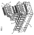
- the present invention is a surge protector cartridge intended for use in a modular connecting block system of the type shown in FIG. 1.
- a mounting bracket 10 is shown in FIG. 1 having a plurality of receptacle slots 12.
- Connector modules 14 are mountable within the receptacle slots 12 between support posts 16 of the mounting bracket 10.
- Each of the connector modules includes multiple terminals, for example, IDC terminals on the front and rear sides thereof. Placement of multiple connector modules 14 within the mounting bracket 10 enables the creation of a double-sided connecting block.
- the mounting bracket 10 as shown in FIG. 1 is hinged in order to allow easy acccess to both the front and rear of the connecting block.
- the connector modules 14 of FIG. 1 are shown with terminal caps 18 on the front and rear of the modules.
- the terminal caps 18 act to protect the IDC terminals and the connections made thereto from handling.
- the terminal caps 18 (and the connector modules) include centrally located apertures 22 which are adapted to receive leads extending from the protector cartridges, as will be explained.
- FIGs. 1A and 1B in connection with one another, there is shown one preferred embodiment of the present invention protector cartridge 20 as it mounts within a connector module 14.
- the mounting bracket is filled with multiple connector modules 14 to thereby form a connecting block.
- the protector cartridge is mountable in the front or rear of a connecting module within the connecting block.
- FIG. 1A shows the protector cartridge 20 mounted within the front side of a connector module 20
- FIG. lB show the protector cartridge mounded within the rear of the connector module in the rear of the connecting block.
- the protector cartridge 20 is intended to provide voltage surge protection for an entire row of connectors, for example, 8 or 10 pairs of connectors, within a terminal block of connector modules.
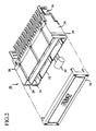
- the cartridge includes a housing unit 24 comprised of an upper housing 26 and a lower housing 28 which are adapted to mate with one another.
- the upper housing 28 includes a first and second cavity 29, 31 adapted to receive circuit protection devices 30, for example, three terminal gas tubes, varistors or other solid state protection devices.
- the protection devices 30 once mounted within the housing, are located well below the top surface 32 of the housing 24. This provides the surge protection devices 30 with increased protection from handling while being mounted within the connector block.
- Terminal leads of the protector cartridge are insertable into a connector module 14 where the terminal leads couple internally with the terminals of the connector module to thereby provide overvoltage protection for the entire row of connectors.
- the protector cartridge 20 also couples to the mounting bracket 10 by way of metallic flaps 34 located on either side of the housing 24, which flaps connect to the support posts 16 of FIG. 1.
- the flaps 34 are internally coupled to a ground bus within the cartridge housing 24 to thereby provide an electrical discharge path through the mounting bracket.
- An optional cover 36 is also shown in FIG. 2 which is adapted to clip onto the upper housing 26 in order to cover the protection devices 30.
- the present invention protector cartridge 20 is used as a voltage-only surge protector, the mounting orientation within the connector block need not be polarity specific. This is because the protection device need not necessarily be inserted in series within the circuit.
- the present invention protector cartridge 20 is adapted for mounting in either the front or rear of a connector module 14.
- the protector cartridge is symmetrical about a vertical axis X and, as such, a 180 degree rotation in insertion of the cartridge is allowable.
- insertion orientation is of no concern, as long as the terminals of the protector cartridge seat within the apertures 22 of the connector module 14 shown in FIG. 1.
- the ground bracket 40 is essentially an L-shaped member having a plurality of cantilever-type clips 42 coupled to a first section thereof.
- the cantilever clips 42 couple with the ground lead of the protection device to provide a minimum predetermined force, for example 1 lb., in a type of force fit.
- a flap section 34 of the ground bracket 40 couples with the mounting bracket 10, as mentioned previously, to provide an electrical discharge path for any surge which is received on a protected circuit.
- Two of the brackets 40 are assembled within the protector cartridge 20 opposite one another in order to form a rectangular ground bus.
- the ground bracket and cantilever clips 42 as shown comprise a unitary arrangement.
- bracket 40 By providing the bracket 40 as a unitary component assembly costs are significantly reduced in the manufacturing process since less parts need be assembled.
- the cantilever clips 42 may also be enabled to be detachable from the ground bar to allow for simple replacement.
- the ground bus will be made from a suitable conductive material in order to provide an electrical discharge path in response to an electrical surge.
- FIG. 4A there is shown an exemplary embodiment of a contact spring 46 used with the present invention cartridge protector 20.
- the contact spring includes an elongated vertically extending member 48 which forms the contact to the connector module 14.
- a horizontal extension member 50 extends perpendicularly transverse to the vertical member 48.
- the horizontal member 50 of the contact spring 46 terminates vertically in a cantilever contact 52 similar to those found on the contacts of the ground bar 40.
- a second spring contact 47 includes a vertical member 49 having an essentially 90 degree bend and then terminating vertically with a cantilever clip 51.
- the spring contacts 46, 47 are inserted within the housing of the protector cartridge 20, wherein the vertical members 48, 49 make contact internally to contacts within a connector module 14.
- Pairs of spring contacts 46, 47 will generally couple with a terminal pair connection, for example, the "tip” and “ring” pair of a telephone circuit.
- the cantilever clips 52, 51 of a pair of spring contacts 46, 47 couple with the two remaining leads of a single three terminal protection device 30.
- the ground terminal of the protection device couples with the cantilever contact 42 of the ground bar 40.
- the spring contacts 46, 47 will be comprised of a suitable conductive material as with the ground bracket 40 and may, for example, be (silver) plated to provide enhanced conductivity.
- FIGs. 5A and 5B in conjunction with one another there is shown a front and rear perspective view, respectively, of the upper and lower housing 26, 28 of the protector cartridge 20 as they would connect to one another.
- the upper housing 26 includes a plurality of flaps 56 which overhang a bottom edge thereof and are adapted to engage corresponding tabs 58 on the lower housing 28 to thereby couple the two housings.
- a top surface 60 of the lower housing 28 shown in FIG. 5A includes a plurality of wells 62, 63 for receiving corresponding sections of contact spring 46, 47 respectively.
- the vertical members 48 of the contact springs 46, 47 are insertable within apertures 65, 67 of the lower housing where they are aligned in a corresponding slot 66 of a finger which extends vertically from the lower housing.
- the wells 62, 63 are adapted to receive and seat the spring contact 46, 47 wherein adjacent contacts seat within adjacent wells.
- each pair of spring contacts 46, 47 which correspond to a pair of terminals within a connector module 14 are seated within separate unconnected wells, wherein the shape of the well 62, 63 corresponds to the shape of the corresponding region of the spring contact 46, 47.
- first and second spring contact 47, 46 corresponding to the first extending finger 70 of the lower housing 28 would be seated in first and second wells 71, 72, respectively, separated by a partition 73.
- This serves to significantly increase the insulation resistance between adjacent terminals and also prevents the occurrence of short circuiting of adjacent leads caused by moisture that may collect within the housing when the device is used within humid environments. Any condensation will collect within the separated wells 62, 63 thus preventing electrical contact between terminals caused by collected moisture.
- the upper and lower housings 26, 28 are adapted to mate with one another with the two L-shaped ground brackets 40 and a predetermined number of spring contacts 46, 47 e.g., 8 or 10 pair, sandwiched between to form the cartridge 20. Final assembly is accomplished by insertion of standard 3-lead commercial configuration protection devices 30, for example, gas tubes including a thermal overload mechanism.
- the bottom facing surface 74 of the upper housing 26 includes a series of protrusions 76 extending outwardly therefrom.
- the purpose of the protrusions 76 is to engage the spring contacts 46, 47, in order that they may seat correctly within the wells 62, 63 between the upper and lower housing.
- an exclusion feature 78 is also shown in FIG. 5B on the bottom surface 77 of the lower housing 28 to prevent insertion of the protector cartridge 20 into certain predetermined sized connector modules 14.
- the exclusion feature 78 would be present on 8-pair protector modules to prevent an 8-pair cartridge form being inserted into a 10-pair connector module.
- the 8-pair and 10-pair protector cartridges use virtually identical components, except that the two pairs of end terminals may be left vacant of protection on the 8-pair module.
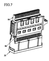
- FIG. 6 shows an 8-pair connector module 80 with a corresponding 8-pair terminal cap 82 while FIG. 7 shows a similar 10-pair arrangement of connector module 84 and terminal cap 86.
- the terminal cap 86 of the 10-pair connector 84 extends fully across the connector module, while the 8-pair combination 80, 82 of FIG. 6 includes voids on either end. Insertion of an 8-pair cartridge into a 10-pair connector module is thus prevented since the exclusion posts 78 contact the terminals and/or terminal cap 86 at the end regions of the connector module 84 to thereby block full insertion.
- a 10-pair protection cartridge without exclusion posts is, however, insertable into an 8-pair connector module because no exclusion feature is present to block insertion.
- FIG. 5B also illustrates the 10 individual sets of three square apertures 89 present within the upper housing 26. These apertures 89 are adapted for insertion of the cantilever clips 52, 51 on the spring contacts 46, 47 and the clips 42 of the ground bracket 40 which couple with the protection devices 30.
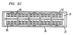
- FIG. 5C shows a top plan view of the upper housing 26.
- Circular retaining regions 90 within the cavities 29, 31 of the upper housing act to stabilize insertion of the protection devices 30 into the cartridge 20.
- identical individual components (with the exception of the removable exclusion feature 78) are used in assembly of the 8 and 10-pair protector cartridges, thereby decreasing overall manufacturing costs.
- the end cavities 92, 93 are simply left unfilled by circuit protection. In the alternative these blank cavities can be used as storage to house spare surge protection devices 30.
- FIG. 8 there is shown a side cross-sectional view of the present invention protector cartridge 20 as it is inserted within a connector module 14.
- the vertical members 48, 49 of the spring contacts 46 or 47 couple internally with the contacts 95, 96 of the connector module to thereby provide surge protection for contacts at both the front and rear of the module.
Landscapes
- Details Of Connecting Devices For Male And Female Coupling (AREA)
- Connector Housings Or Holding Contact Members (AREA)
- Emergency Protection Circuit Devices (AREA)
- Coupling Device And Connection With Printed Circuit (AREA)
Applications Claiming Priority (2)
| Application Number | Priority Date | Filing Date | Title |
|---|---|---|---|
| US08/502,522 US5627721A (en) | 1995-07-14 | 1995-07-14 | Protector cartridge for modular connector blocks |
| US502522 | 1995-07-14 |
Publications (1)
| Publication Number | Publication Date |
|---|---|
| EP0753907A2 true EP0753907A2 (de) | 1997-01-15 |
Family
ID=23998216
Family Applications (1)
| Application Number | Title | Priority Date | Filing Date |
|---|---|---|---|
| EP96304899A Withdrawn EP0753907A2 (de) | 1995-07-14 | 1996-07-03 | Schutzeinheit für modulare Verbindungsblöcke |
Country Status (10)
| Country | Link |
|---|---|
| US (1) | US5627721A (de) |
| EP (1) | EP0753907A2 (de) |
| JP (1) | JPH09180826A (de) |
| KR (1) | KR970008738A (de) |
| CN (1) | CN1147139A (de) |
| BR (1) | BR9603058A (de) |
| CA (1) | CA2177867A1 (de) |
| PL (1) | PL315166A1 (de) |
| TW (1) | TW274648B (de) |
| ZA (1) | ZA965835B (de) |
Cited By (4)
| Publication number | Priority date | Publication date | Assignee | Title |
|---|---|---|---|---|
| FR2764741A1 (fr) * | 1997-06-17 | 1998-12-18 | Smiths Industries Plc | Ensemble electrique |
| US6556411B1 (en) | 2002-04-02 | 2003-04-29 | Marconi Communications, Inc. | Purge protection cartridge with three-way attachment clip |
| US6814631B2 (en) | 2002-04-02 | 2004-11-09 | Marconi Intellectual Property (Ringfence) Inc. | Electrical terminal for surge protection cartridge |
| WO2004114466A1 (en) * | 2003-06-25 | 2004-12-29 | Crevis Co., Ltd. | Signal processing module of industrial machines |
Families Citing this family (34)
| Publication number | Priority date | Publication date | Assignee | Title |
|---|---|---|---|---|
| US5696820A (en) * | 1995-09-13 | 1997-12-09 | Oneac Corporation | Telephone and data communications line conditioner system |
| JPH11307184A (ja) * | 1998-04-16 | 1999-11-05 | Kansei Corp | 多極コネクタ |
| AUPP308498A0 (en) * | 1998-04-20 | 1998-05-14 | Krone Aktiengesellschaft | Electrical connector |
| US6122156A (en) * | 1998-09-15 | 2000-09-19 | Edco, Inc. Of Florida | Surge suppression system |
| US6166894A (en) * | 1999-03-15 | 2000-12-26 | Lucent Technologies Inc. | PCB based protector cartridge |
| US6297612B1 (en) | 1999-08-27 | 2001-10-02 | Robotic Control Group, L.L.C. | Motion control coupling apparatus |
| DE10208698B4 (de) * | 2002-02-28 | 2004-03-04 | Dehn + Söhne Gmbh + Co. Kg | Überspannungsschutz-Modul, Überspannungsschutz-Anordnung, insbesondere für Telekommunikations-Einrichtungen, sowie Erdungsanordnung für die Trennleiste der Überspannungs-Schutzanordnung |
| DE60335603D1 (de) * | 2003-03-03 | 2011-02-17 | 3M Innovative Properties Co | Anordnung von Telekommunikationsmodulen mit wenigstens einem Schutzstecker |
| DE102004061681B4 (de) | 2004-12-22 | 2006-10-26 | Adc Gmbh | Kabelsteckverbinder für Leiterplatten |
| US7303446B2 (en) * | 2005-05-18 | 2007-12-04 | 3M Innovative Proprties Company | Frame assembly |
| US20060264090A1 (en) * | 2005-05-18 | 2006-11-23 | Dower William V | Electrical connector assembly and method of forming the same |
| USD591691S1 (en) | 2007-02-28 | 2009-05-05 | Adc Telecommunications, Inc. | Overvoltage protection plug |
| US8064182B2 (en) * | 2007-02-28 | 2011-11-22 | Adc Telecommunications, Inc. | Overvoltage protection plug |
| DE102007026094B4 (de) * | 2007-06-05 | 2023-05-11 | Tyco Electronics Services Gmbh | Kontaktelement für einen Steckverbinder für Leiterplatten |
| DE102007026095A1 (de) * | 2007-06-05 | 2008-12-11 | Adc Gmbh | Erdkamm, insbesondere für einen Steckverbinder für Leiterplatten |
| US7946863B2 (en) * | 2008-04-25 | 2011-05-24 | Adc Telecommunications, Inc. | Circuit protection block |
| US8411404B2 (en) * | 2008-05-27 | 2013-04-02 | Adc Telecommunications, Inc. | Overvoltage protection plug |
| USD620896S1 (en) | 2008-05-27 | 2010-08-03 | Adc Telecommunications, Inc. | Overvoltage protection plug |
| US11251608B2 (en) | 2010-07-13 | 2022-02-15 | Raycap S.A. | Overvoltage protection system for wireless communication systems |
| US8995106B2 (en) * | 2011-02-08 | 2015-03-31 | Raycap, S.A. | Overvoltage protection system for wireless communication systems |
| KR101179879B1 (ko) | 2011-12-28 | 2012-09-05 | 주식회사 성진테크윈 | 조합식 서지보호기 |
| US9099860B2 (en) | 2012-12-10 | 2015-08-04 | Raycap Intellectual Property Ltd. | Overvoltage protection and monitoring system |
| US9640986B2 (en) | 2013-10-23 | 2017-05-02 | Raycap Intellectual Property Ltd. | Cable breakout assembly |
| US9575277B2 (en) | 2015-01-15 | 2017-02-21 | Raycap, S.A. | Fiber optic cable breakout assembly |
| US9257788B1 (en) * | 2015-01-23 | 2016-02-09 | Oracle International Corporation | Connector retention and alignment assembly for use in computer and data storage mounting racks |
| CN105977693B (zh) * | 2015-03-11 | 2020-06-12 | 菲尼克斯电气公司 | 用于容置模块式接触嵌件的托架 |
| US10802237B2 (en) | 2015-11-03 | 2020-10-13 | Raycap S.A. | Fiber optic cable management system |
| US9971119B2 (en) | 2015-11-03 | 2018-05-15 | Raycap Intellectual Property Ltd. | Modular fiber optic cable splitter |
| EP3571566A4 (de) | 2017-01-20 | 2021-01-06 | Raycap, S.A. | Kraftübertragungssystem für drahtloskommunikationssysteme |
| US10971928B2 (en) | 2018-08-28 | 2021-04-06 | Raycap Ip Assets Ltd | Integrated overvoltage protection and monitoring system |
| CN109980423B (zh) * | 2019-04-25 | 2020-07-31 | 台州沃博进出口有限公司 | 一种多功能开关插座 |
| US11677164B2 (en) | 2019-09-25 | 2023-06-13 | Raycap Ip Assets Ltd | Hybrid antenna distribution unit |
| CN113645779B (zh) * | 2020-04-27 | 2023-02-10 | 佛山市顺德区顺达电脑厂有限公司 | 机架总成 |
| US12237134B2 (en) | 2021-12-28 | 2025-02-25 | Raycap Ip Assets Ltd | Circuit protection for hybrid antenna distribution units |
Family Cites Families (3)
| Publication number | Priority date | Publication date | Assignee | Title |
|---|---|---|---|---|
| US4603377A (en) * | 1983-10-24 | 1986-07-29 | Nec Corporation | Main distributing frame board for an electronic switching system |
| US4584624A (en) * | 1984-12-10 | 1986-04-22 | Northern Telecom Limited | Station protector for telecommunications systems |
| US4800587A (en) * | 1987-05-11 | 1989-01-24 | Northern Telecom Limited | Telephone line protector with line disconnect and an entrance terminal assembly incorporating a plurality of protectors |
-
1995
- 1995-07-14 US US08/502,522 patent/US5627721A/en not_active Expired - Lifetime
- 1995-08-22 TW TW084108757A patent/TW274648B/zh active
-
1996
- 1996-05-31 CA CA002177867A patent/CA2177867A1/en not_active Abandoned
- 1996-07-03 EP EP96304899A patent/EP0753907A2/de not_active Withdrawn
- 1996-07-09 PL PL96315166A patent/PL315166A1/xx unknown
- 1996-07-10 ZA ZA965835A patent/ZA965835B/xx unknown
- 1996-07-11 BR BR9603058A patent/BR9603058A/pt not_active Application Discontinuation
- 1996-07-11 CN CN96110649A patent/CN1147139A/zh active Pending
- 1996-07-12 JP JP8182582A patent/JPH09180826A/ja active Pending
- 1996-07-12 KR KR1019960028778A patent/KR970008738A/ko not_active Withdrawn
Cited By (5)
| Publication number | Priority date | Publication date | Assignee | Title |
|---|---|---|---|---|
| FR2764741A1 (fr) * | 1997-06-17 | 1998-12-18 | Smiths Industries Plc | Ensemble electrique |
| US5997348A (en) * | 1997-06-17 | 1999-12-07 | Smiths Industries Public Limited Company | Electrical assembly with grounding strip connecting cable screens |
| US6556411B1 (en) | 2002-04-02 | 2003-04-29 | Marconi Communications, Inc. | Purge protection cartridge with three-way attachment clip |
| US6814631B2 (en) | 2002-04-02 | 2004-11-09 | Marconi Intellectual Property (Ringfence) Inc. | Electrical terminal for surge protection cartridge |
| WO2004114466A1 (en) * | 2003-06-25 | 2004-12-29 | Crevis Co., Ltd. | Signal processing module of industrial machines |
Also Published As
| Publication number | Publication date |
|---|---|
| TW274648B (en) | 1996-04-21 |
| PL315166A1 (en) | 1997-01-20 |
| CN1147139A (zh) | 1997-04-09 |
| KR970008738A (ko) | 1997-02-24 |
| CA2177867A1 (en) | 1997-01-15 |
| ZA965835B (en) | 1997-04-16 |
| US5627721A (en) | 1997-05-06 |
| BR9603058A (pt) | 1998-05-05 |
| JPH09180826A (ja) | 1997-07-11 |
Similar Documents
| Publication | Publication Date | Title |
|---|---|---|
| US5627721A (en) | Protector cartridge for modular connector blocks | |
| US5546267A (en) | Communication circuit protector | |
| US5086368A (en) | Connector bank with voltage surge protection | |
| US7946863B2 (en) | Circuit protection block | |
| US5595507A (en) | Mounting bracket and ground bar for a connector block | |
| US3936133A (en) | Connector block for telephone equipment | |
| US7768794B1 (en) | Surge suppression device with replaceable surge suppression modules | |
| US6193556B1 (en) | Electrical terminal array with insulation displacement connectors and surge arrestors | |
| EP0743701A2 (de) | Schneidklemmkontakt mit Haltemitteln | |
| US6196869B1 (en) | Mounting bracket and power bus for a connector block | |
| US5816854A (en) | Mounting bracket for connector block | |
| US5643014A (en) | Mounting of protectors in connector blocks | |
| US5622516A (en) | Insulation displacement terminal with two-wire insertion capability | |
| EP1495522B1 (de) | Überspannungsschutzkassette | |
| US5483409A (en) | 25-pair circuit protection assembly | |
| US5805404A (en) | Common insulating housing for elements of varying terminals | |
| US20080124986A1 (en) | Plugless normally-open connector module | |
| US6093041A (en) | Connector block with internal power bus | |
| US6243250B1 (en) | Electrical connector | |
| MXPA96002610A (en) | Protective cartridge for blocks connectorsmodula | |
| AU741657B2 (en) | Electrical connector | |
| EP1482744A1 (de) | Anschlussblock für ADSL | |
| TH24170A (th) | ตลับตัวป้องกันสำหรับกล่องหน่วยต่อชิ้นส่วน |
Legal Events
| Date | Code | Title | Description |
|---|---|---|---|
| PUAI | Public reference made under article 153(3) epc to a published international application that has entered the european phase |
Free format text: ORIGINAL CODE: 0009012 |
|
| AK | Designated contracting states |
Kind code of ref document: A2 Designated state(s): DE FR GB IT NL SE |
|
| STAA | Information on the status of an ep patent application or granted ep patent |
Free format text: STATUS: THE APPLICATION HAS BEEN WITHDRAWN |
|
| 18W | Application withdrawn |
Withdrawal date: 19971027 |