EP1495522B1 - Überspannungsschutzkassette - Google Patents
Überspannungsschutzkassette Download PDFInfo
- Publication number
- EP1495522B1 EP1495522B1 EP03746063A EP03746063A EP1495522B1 EP 1495522 B1 EP1495522 B1 EP 1495522B1 EP 03746063 A EP03746063 A EP 03746063A EP 03746063 A EP03746063 A EP 03746063A EP 1495522 B1 EP1495522 B1 EP 1495522B1
- Authority
- EP
- European Patent Office
- Prior art keywords
- housing
- cartridge
- clip
- surge protection
- guide strip
- Prior art date
- Legal status (The legal status is an assumption and is not a legal conclusion. Google has not performed a legal analysis and makes no representation as to the accuracy of the status listed.)
- Expired - Lifetime
Links
- 238000005192 partition Methods 0.000 claims description 8
- 238000009434 installation Methods 0.000 abstract description 4
- 239000000463 material Substances 0.000 description 5
- PXHVJJICTQNCMI-UHFFFAOYSA-N Nickel Chemical compound [Ni] PXHVJJICTQNCMI-UHFFFAOYSA-N 0.000 description 4
- 230000000712 assembly Effects 0.000 description 3
- 238000000429 assembly Methods 0.000 description 3
- 230000006378 damage Effects 0.000 description 3
- 238000013461 design Methods 0.000 description 3
- 238000003780 insertion Methods 0.000 description 3
- 230000037431 insertion Effects 0.000 description 3
- 238000012986 modification Methods 0.000 description 3
- 230000004048 modification Effects 0.000 description 3
- 229910000906 Bronze Inorganic materials 0.000 description 2
- RYGMFSIKBFXOCR-UHFFFAOYSA-N Copper Chemical compound [Cu] RYGMFSIKBFXOCR-UHFFFAOYSA-N 0.000 description 2
- OAICVXFJPJFONN-UHFFFAOYSA-N Phosphorus Chemical compound [P] OAICVXFJPJFONN-UHFFFAOYSA-N 0.000 description 2
- 239000010974 bronze Substances 0.000 description 2
- 238000010276 construction Methods 0.000 description 2
- 229910052802 copper Inorganic materials 0.000 description 2
- 239000010949 copper Substances 0.000 description 2
- KUNSUQLRTQLHQQ-UHFFFAOYSA-N copper tin Chemical compound [Cu].[Sn] KUNSUQLRTQLHQQ-UHFFFAOYSA-N 0.000 description 2
- 230000014759 maintenance of location Effects 0.000 description 2
- 239000002184 metal Substances 0.000 description 2
- 229910052751 metal Inorganic materials 0.000 description 2
- 229910052759 nickel Inorganic materials 0.000 description 2
- 229920000728 polyester Polymers 0.000 description 2
- 230000001012 protector Effects 0.000 description 2
- SYJPAKDNFZLSMV-HYXAFXHYSA-N (Z)-2-methylpropanal oxime Chemical compound CC(C)\C=N/O SYJPAKDNFZLSMV-HYXAFXHYSA-N 0.000 description 1
- 229910000831 Steel Inorganic materials 0.000 description 1
- ATJFFYVFTNAWJD-UHFFFAOYSA-N Tin Chemical compound [Sn] ATJFFYVFTNAWJD-UHFFFAOYSA-N 0.000 description 1
- 208000027418 Wounds and injury Diseases 0.000 description 1
- 239000004020 conductor Substances 0.000 description 1
- 230000000994 depressogenic effect Effects 0.000 description 1
- 230000001066 destructive effect Effects 0.000 description 1
- 238000006073 displacement reaction Methods 0.000 description 1
- 238000005516 engineering process Methods 0.000 description 1
- 238000010438 heat treatment Methods 0.000 description 1
- 208000014674 injury Diseases 0.000 description 1
- 238000009413 insulation Methods 0.000 description 1
- 230000007257 malfunction Effects 0.000 description 1
- 238000004519 manufacturing process Methods 0.000 description 1
- 238000005259 measurement Methods 0.000 description 1
- 230000007246 mechanism Effects 0.000 description 1
- 238000000034 method Methods 0.000 description 1
- 230000003014 reinforcing effect Effects 0.000 description 1
- 239000007779 soft material Substances 0.000 description 1
- 239000007787 solid Substances 0.000 description 1
- 239000010959 steel Substances 0.000 description 1
- OSKILZSXDKESQH-UHFFFAOYSA-K zinc;iron(2+);phosphate Chemical compound [Fe+2].[Zn+2].[O-]P([O-])([O-])=O OSKILZSXDKESQH-UHFFFAOYSA-K 0.000 description 1
Images




Classifications
-
- H—ELECTRICITY
- H04—ELECTRIC COMMUNICATION TECHNIQUE
- H04Q—SELECTING
- H04Q1/00—Details of selecting apparatus or arrangements
- H04Q1/02—Constructional details
- H04Q1/11—Protection against environment
- H04Q1/116—Protection against environment lightning or EMI protection, e.g. shielding or grounding
-
- H—ELECTRICITY
- H01—ELECTRIC ELEMENTS
- H01R—ELECTRICALLY-CONDUCTIVE CONNECTIONS; STRUCTURAL ASSOCIATIONS OF A PLURALITY OF MUTUALLY-INSULATED ELECTRICAL CONNECTING ELEMENTS; COUPLING DEVICES; CURRENT COLLECTORS
- H01R9/00—Structural associations of a plurality of mutually-insulated electrical connecting elements, e.g. terminal strips or terminal blocks; Terminals or binding posts mounted upon a base or in a case; Bases therefor
- H01R9/22—Bases, e.g. strip, block, panel
- H01R9/24—Terminal blocks
- H01R9/2425—Structural association with built-in components
- H01R9/2441—Structural association with built-in components with built-in overvoltage protection
-
- H—ELECTRICITY
- H01—ELECTRIC ELEMENTS
- H01R—ELECTRICALLY-CONDUCTIVE CONNECTIONS; STRUCTURAL ASSOCIATIONS OF A PLURALITY OF MUTUALLY-INSULATED ELECTRICAL CONNECTING ELEMENTS; COUPLING DEVICES; CURRENT COLLECTORS
- H01R9/00—Structural associations of a plurality of mutually-insulated electrical connecting elements, e.g. terminal strips or terminal blocks; Terminals or binding posts mounted upon a base or in a case; Bases therefor
- H01R9/22—Bases, e.g. strip, block, panel
- H01R9/24—Terminal blocks
- H01R9/2483—Terminal blocks specially adapted for ground connection
-
- H—ELECTRICITY
- H01—ELECTRIC ELEMENTS
- H01R—ELECTRICALLY-CONDUCTIVE CONNECTIONS; STRUCTURAL ASSOCIATIONS OF A PLURALITY OF MUTUALLY-INSULATED ELECTRICAL CONNECTING ELEMENTS; COUPLING DEVICES; CURRENT COLLECTORS
- H01R13/00—Details of coupling devices of the kinds covered by groups H01R12/70 or H01R24/00 - H01R33/00
- H01R13/02—Contact members
- H01R13/10—Sockets for co-operation with pins or blades
- H01R13/11—Resilient sockets
- H01R13/112—Resilient sockets forked sockets having two legs
-
- H—ELECTRICITY
- H01—ELECTRIC ELEMENTS
- H01R—ELECTRICALLY-CONDUCTIVE CONNECTIONS; STRUCTURAL ASSOCIATIONS OF A PLURALITY OF MUTUALLY-INSULATED ELECTRICAL CONNECTING ELEMENTS; COUPLING DEVICES; CURRENT COLLECTORS
- H01R13/00—Details of coupling devices of the kinds covered by groups H01R12/70 or H01R24/00 - H01R33/00
- H01R13/40—Securing contact members in or to a base or case; Insulating of contact members
- H01R13/405—Securing in non-demountable manner, e.g. moulding, riveting
- H01R13/41—Securing in non-demountable manner, e.g. moulding, riveting by frictional grip in grommet, panel or base
-
- H—ELECTRICITY
- H01—ELECTRIC ELEMENTS
- H01R—ELECTRICALLY-CONDUCTIVE CONNECTIONS; STRUCTURAL ASSOCIATIONS OF A PLURALITY OF MUTUALLY-INSULATED ELECTRICAL CONNECTING ELEMENTS; COUPLING DEVICES; CURRENT COLLECTORS
- H01R13/00—Details of coupling devices of the kinds covered by groups H01R12/70 or H01R24/00 - H01R33/00
- H01R13/46—Bases; Cases
- H01R13/502—Bases; Cases composed of different pieces
- H01R13/506—Bases; Cases composed of different pieces assembled by snap action of the parts
-
- H—ELECTRICITY
- H01—ELECTRIC ELEMENTS
- H01R—ELECTRICALLY-CONDUCTIVE CONNECTIONS; STRUCTURAL ASSOCIATIONS OF A PLURALITY OF MUTUALLY-INSULATED ELECTRICAL CONNECTING ELEMENTS; COUPLING DEVICES; CURRENT COLLECTORS
- H01R2201/00—Connectors or connections adapted for particular applications
- H01R2201/16—Connectors or connections adapted for particular applications for telephony
-
- H—ELECTRICITY
- H04—ELECTRIC COMMUNICATION TECHNIQUE
- H04Q—SELECTING
- H04Q1/00—Details of selecting apparatus or arrangements
- H04Q1/02—Constructional details
- H04Q1/14—Distribution frames
- H04Q1/142—Terminal blocks for distribution frames
Definitions
- the present invention relates to a surge protection cartridge and more particularly to a stronger, more effective and more efficient surge protection cartridge.
- the protector cartridge mounts in the front or rear of a connector module of the connector block in a variety of orientations in order to protect an entire row of terminations on the block.
- Two L-shaped brackets adapted to couple to a mounting bracket of the connector block form an internal ground bus within the protector cartridge.
- the brackets include a series of cantilever connecting clips which couple directly to the surge protection devices.
- a surge protection cartridge for a modular terminal block assembly comprising: a housing adapted to be connected to a modular terminal block; a plurality of electrical terminals mounted to the housing; a grounding element mounted to the housing; and, an attachment clip mounted to the housing for connecting the housing to a frame and for connecting the housing to a terminal block assembly.
- FIGURE 1 is a partially exploded isometric view of a surge protection cartridge without surge protection devices.
- FIGURE 2 is a partially exploded isometric view of the surge protection device shown in FIGURE 1 and including surge protection devices.
- FIGURE 3 is a sectional elevation view of the surge protection cartridge but without tip and ring terminals.
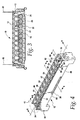
- FIGURE 4 is a downward looking isometric view of a housing of the surge protection cartridge.
- FIGURE 5 is an upward looking isometric view of the housing of FIGURE 4 partially broken away.
- FIGURE 6 is a top plan view of a portion of the housing taken within circle 6-6 of FIGURE 4 .
- FIGURE 7 is a bottom plan view of a portion of the housing taken within circle 7-7 of FIGURE 5 .
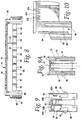
- FIGURE 8 is a sectional elevation view of the housing taken along line 8-8 of FIGURE 4 .
- FIGURE 9 is a sectional elevation view of the housing taken along line 9-9 of FIGURE 4 .
- FIGURE 9a is a sectional elevation view of the housing taken along line 9a-9a of FIGURE 4 .
- FIGURE 10 is a partial sectional elevation view of the housing taken along line 10-10 of FIGURE 7 .
- FIGURE 11 is a front isometric view of an attachment clip of the surge protection cartridge.
- FIGURE 12 is a rear isometric view of the attachment clip of the surge protection cartridge.
- FIGURE 13 is a sectional elevation view of the attachment clip taken along line 13-13 of FIGURE 12 .
- FIGURE 14 is a fragmentary isometric view of a standard telephony mounting frame.
- FIGURE 15 is an isometric view of a grounding element of the surge protection cartridge.
- FIGURE 16 is a downward looking isometric view of a guiding strip of the surge protection cartridge.
- FIGURE 17 is an upward looking isometric view of the guide strip of the surge protection cartridge.
- FIGURE 18 is a top plan view of a portion of the guide strip taken within circle 18-18 of FIGURE 16 .
- FIGURE 19 is a sectional elevation view of the guide strip taken along line 19-19 of FIGURE 16 .
- FIGURE 20 is an upward looking isometric view of a cover of the surge protection cartridge.
- FIGURE 21 is a downward looking isometric view of the cover of the surge protection cartridge.
- FIGURE 22 is an isometric view of a tip terminal of the surge protection cartridge.
- FIGURE 23 is an isometric view of a ring terminal of the surge protection cartridge.
- FIGURE 24 is an isometric view, partially exploded, of a surge protection cartridge and an additional attachment clip.
- FIGURES 1, 2 and 3 an example of the invention in the form of a surge protection cartridge 10 is illustrated.
- the exploded isometric views of FIGURES 1 and 2 each shows a partial surge protection cartridge, as does the cross-sectional elevation view of FIGURE 3 .
- FIGURES 1-3 shows all of the elements of the surge protection cartridge.
- the cartridge 10 includes a ten-pair housing 12, a grounding element 13, tip and ring terminals such as the terminals 14, 15, a guide strip 16, a pair of attachment clips 18, 20, a cover 22, and ten surge protection devices such as the over-voltage/over-current protection devices 24, 25, 26.
- the housing 12 includes longitudinally directed, short height, side walls 30, 32 and end walls 34, 36. Opposing connection projections 38, 40 integral with the side walls 30, 32, respectively, are provided for making connection to the cover 22 as will be explained below.
- the housing is divided into ten compartments 42, 44, 46, 48, 50, 52, 54, 56, 58, 60, each of which includes a tip terminal opening such as the openings 62, 62a, 62b, and a ring terminal opening such as the openings 64, 64a, 64b.
- Retention openings 61, 61a, 61b, 63, 63a are provided for the tip terminal
- retention openings 65, 65a are provided for the ring terminal as will also be explained below.
- the side walls 30, 32 are relatively short from a top edge 66 to a bottom edge 68. This shortness exposes the protection devices 24, 25, 26 as shown in FIGURE 2 , which provides a major advantage of the present invention, namely the ability to install and remove protection devices by hand and without the use of any tools.
- the housing includes an interior top wall 70, FIGURE 9 , extending almost the entire longitudinal length of the housing for receiving the grounding element 16.
- the grounding element is frictionally engaged with the housing along two interior, longitudinally extending walls 71, 72.
- Each wall also includes a guide flange, 73, 74, FIGURE 5 , respectively, which is received in a corresponding notch 75, 76, FIGURE 15 , respectively, in the sides of the grounding element.
- the housing also includes two snap retainers 67, 69, FIGURE 9a , which also engage the grounding element 13. Once the grounding element is mounted in the housing, it will remain mechanically and frictionally engaged until purposefully disengaged.
- a series of interior ledges in the housing such as the ledge 77, for abutting and positioning the guide strip 16 and side flanges, such as the flange 78, for guiding and frictionally engaging the guide strip.
- a sleeve 80 for receiving the first attachment clip 18
- a sleeve 82 for receiving the second attachment clip 20.
- the left end portion includes an outer wall 84 with a notch 85, the end wall 34, and an inner wall 88.
- the attachment clip 18 is inserted between the end wall 34 and the inner wall 88 and frictionally engages the end wall 34.
- a disengagement handle extends through the notch 85 and beyond the outer wall 84.
- the housing is constructed of an electrically insulative material such as polyester, and sold under the brand Valox DR-48, with a uniform wall thickness of about 0.05 inches. All of the just described elements may be made as an integrally molded part.
- the housing acts as a mount for the other elements of the surge protection cartridge as shown in FIGURES 1-3 .
- the attachment clip 18 is shown in more detail.
- the other attachment clip 20 is identical.
- the attachment clip is a strip of metal formed with an upper portion 90 and a somewhat offset lower portion 92.
- Three flexible beams 94, 96, 98 are formed by two slots 100, 102 beginning in the upper portion 90 and extending through the lower portion 92.
- the upper portion 90 of the attachment clip includes a square opening 104 which may be used to connect the surge protection cartridge to a modular terminal block assembly.
- the outer beams 94, 98 include return-curve arm portions 106, 108 which are flexible enough to allow the attachment clip to make a frictional fit with the end wall 34 of the housing 12.
- the outer beams also include barbs 107, 109 for making a strong interference fit with the end wall 34 of the housing 12.
- the end wall is received between the lower portion 92 and the arm portions 106, 108.
- the arm portions flex and provide a biasing force normal to the end wall.
- the middle beam 96 includes a curlycue handle 110.
- the handle extends beyond the notch 85 in the outer wall 84 of the housing when the clip is attached.
- the middle beam 96 also includes a connector projection 112 formed to mate with a post-opening of a mounting frame typically used in telecommunication networks.
- the handle 110 may be pressed outwardly by a technician to disengage the connector projection 112 from the frame post.
- the material of the attachment clip may be AISI 1050 steel, annealed, with a heat treatment to 42-48 HRC and then finished with black zinc iron phosphate and oil.
- the purpose of the attachment clip is to act as a three-way connector. First, the attachment clip connects itself to the housing. Second, the clip also connects the surge protection cartridge to a modular terminal block assembly and third, the clip connects the entire assembly, including the cartridge, to a standard mounting frame.
- a standard metal mounting frame 114 is illustrated in FIGURE 14 . It exemplifies the frame or bracket of the type used in telecommunication networks. Modular terminal block assemblies which are used to make connections in such networks are mounted to the frame on opposing pairs of upstanding flanges or posts such as the posts 115, 116. Such frames may be seen in earlier U.S. Patents 5, 627, 721 and 5, 779, 504 .
- the surge protection cartridge 10 is also structured to be supported by a pair of posts. Each post has an opening such as the opening 117, and it is in this opening into which the connector projection 112 of the attachment clip 18 is received. Once received, an interference engagement with the frame is completed. To release the surge protection cartridge from the frame, a technician pulls the handles 110 outwardly.
- the post surface around the opening 117, and designated 118, is available for electrical contact with the grounding element 13.
- the ease of mounting the surge protection cartridge on a standard network frame highlights still another advantage of the present invention.
- the cartridge is compact, easily installed and removed from a standard frame, and requires no special tools. As space is always at a premium, no more is required by the new cartridge and yet a far more effective and efficient device is offered.
- the grounding element or ground bar includes a bridge or spine portion 120, a pair of flexible spring contact ends 122, 123, each of the pair having two spring fingers 124, 125, and a series of paired ground clips, such as the ground clips 126, 127.
- the grounding bar may be made of Olin Brass phosphor bronze C5 10 formed from a strip approximately 0.020 inches in thickness with a post-plate electro tin over nickel over copper flash.
- Each of the paired ground clips make electrical contact with a corresponding ground lead from one of the ten protection devices, such as the devices 24, 25, 26.
- the spring contact ends 122, 123 in turn make contact with the mounting frame in the post region 118, FIGURE 14 .
- the bridge portion 120 is mounted to the housing between the interior walls 71, 72 and lies along the top wall 70.
- the attachment clip is not a required part of the ground circuit.
- the attachment clip does not need to be constructed to make good electrical contact with any other element.
- the design of the attachment clip may be focused solely on making a robust mechanical connection between the surge protection cartridge, the modular terminal block assembly and the mounting frame. It is the grounding element that is designed specifically for completing an electrical ground circuit between the surge protection devices and the mounting frame.
- the guide strip 16 is shown in more detail.
- the guide strip cooperates with the housing and is divided into ten separate receptor bays 130, 132, 134, 136, 138, 140, 142, 144, 146, 148, where each bay includes a pad such as the pads 150, 150a and each pad includes three openings such as the openings 152,152a, 154, 154a, 156, 156a.
- Each pad is adjacent an upstanding partition, there being nine partitions alternating with the ten pads.
- the partitions such as the partition 158, define a bay and separate the bays from one another. Bordering each of the three openings are slanted funnel-like surfaces 160, 160a, 162, 162a, 164, 164a.
- the funnel-like surfaces around the openings enhance insertion of the three-lead surge protection devices so as to minimize the likelihood of damage to the soft material leads of the devices.
- the funnel-like surfaces also allow faster protection device insertion since the surfaces direct the leads to the openings and to connections with the terminals.
- a guide notch such as the guide notches 166, 166a.
- the guide notches receive the side flanges 78, FIGURE 5 , of the housing 12.
- the side flanges align, guide and provide frictional engagement for the guide strip.
- Also guiding, aligning and frictionally engaging the housing are two depending feet 168, 170 extending from a bottom surface 172 of the guide strip.
- the guide strip may be made out of any suitable electrically insulated material such as PBT and may be molded as an integral piece.
- the thickness of the guide strip is generally about 0,889 mm (0.035 inches).
- the purpose of the guide strip is to cradle the protection devices, to allow the ends of the protection devices to be gripped by the fingers of a technician and thereby allow installation and removal of the protection devices without tools.
- the "open" design of the guide strip allows sufficient space for the receipt of different types and brands of protection devices, such as gas tubes and solid state devices, both with and without fail-safe mechanisms.
- acceptable devices include those identified as Sankosha 3YVA-90J1F2, Suntech 3YP, Epcos (formerly Siemens) T83, Crydom (formerly Semitron) T10C220E, and the HTA DDP200C.
- the robust cover 22 is shown in FIGURES 20 and 21 .
- the cover includes a base 174, two side walls 176, 178 and two end tabs 180, 182.
- the base includes a depressed central portion 184.
- Each side wall includes an elongated slot 186, 188 for receiving the connector projections 38, 40, FIGURES 5 and 9 , of the side walls of the housing 12.
- Four reinforcing ribs 190, 192, 194, 196 are also formed on the base and side walls.
- the cover may be formed of any suitable insulative material such as polyester and may be molded as an integral piece. Supplementally, the cover secures the protection devices, the guide strip and the grounding element from coming apart even when roughly handled.
- a tip terminal or clip is illustrated in FIGURE 22 .
- the tip clip 14 includes a first contact portion 200, a second contact portion 204 and a spanning bridge portion 202 connecting the two contact portions.
- the tip clip also includes a first connector barb 206 and a second connector barb 208.
- the tip clip is supported on the top surface 210, FIGURE 6 of the housing with the first contact being supported in an upright position, the second contact being received by the openings 62, 62a the first barb being received by the openings 63, 63a and the second barb being received by the openings 61, 61 a.
- the second contact includes a base 212 and two extending arms 214, 216.
- the arms have first parallel portions 218, 220, second converging portions 222, 224 and third diverging portions 226, 228.
- a contact region 230 is formed at the junction of the converging and diverging portions.
- the opening 62 in the housing is surrounded by walls 232, 234, FIGURE 10 , having a depth about equal in measurement to the length of the first portions of the arms.
- the tip clip is mounted to the housing, the outer surfaces of the first portions 218, 220 are closely spaced from the walls 232, 234.
- a suitable spacing between each wall and a first arm portion is 0,0254 mm (0.001 inches). This arrangement has been found to stiffen the arms when they are exposed to a foreign voltage.
- the ring terminal or clip 15 is illustrated in FIGURE 23 .
- the ring clip includes a base portion 240, a first contact portion 242 and a second contact portion 244.
- the ring clip also includes a connector barb 246.
- the second contact portion 244 is disposed to fit into the openings 64, 64a, 64b of the housing while the barb 246 fits within the openings 65, 65a.
- the tip and ring clips are formed of Olin Brass C 7025 phosphor bronze, having a thickness of 0,508 mm (0.020 inches) with a post-plate electro-tin over nickel over copper flash.
- the tip and ring clips form part of the electrical circuit which connects to insulation displacement connectors in the terminal block assembly.
- the surge protection cartridge may be assembled by inserting the tip and ring clips into the housing, by placing the grounding element into the housing so as to have the spine portion 120 of the grounding element located at the interior wall 70 of the housing. Thereafter the guide strip may be inserted.
- Surge protection devices such as the devices 24, 25, 26 may be easily inserted by hand. Leads from the devices are funneled into the openings in the pads of the guide strip.
- the cover 22 is placed over the surge protection devices so that the slots in the cover receive the projections on the housing. An interference fit is established after the side walls of the cover yield to the projections and then snap into place when the slots and projections are aligned.
- the surge protection cartridge may be engaged with a mounting frame simply by inserting opposing posts 115, 116 of the frame 114 into the end portion sleeves 80, 82 of the cartridge, and between the attachment clips 18, 20 and the spring fingers 122, 124 of the grounding element 13.
- a good mechanical engagement is made between the mounting frame and the attachment clips by way of the interference fit between the projection 112 of the attachment clip and the material surrounding the opening 117 of the posts.
- a good electrical contact is formed between the spring fingers of the grounding element and the region 118 of the mounting frame posts.
- a protection cartridge 10a is illustrated as are two additional rod clips 250, 252.
- Each clip has an upper portion 254 for connecting to the attachment clip 20a in the same way that a post from a mounting frame makes a connection.
- Each clip also includes a curved lower portion 256 for making engagement with a rod mounting (not shown here, but shown in U.S. 5,779,504 ), also found in telecommunication networks.
- Another connection may also be made between the surge protection cartridge 10, 10a and a modular terminal block assembly by having the block assembly engage the extending upper portions 90 of the attachment clips which closely resemble the posts of the mounting frame.
- the modular terminal block assembly engages the attachment clips in the same way that the block assembly might directly attach itself to the mounting frame. Namely, each block assembly includes opposing yieldable projections which snap into the openings in the mounting frame posts.
- each attachment clip is pulled outwardly from the cartridge to release the projections from the openings in the posts of the mounting frame.
- the cover may then be removed to access the protection devices to be replaced. It is noted that this entire operation may be accomplished by hand without the use of any kind of tool.
- This feature occurs because of the design of the attachment clips and the housing and with the help of the guide strip. They allow the fingers of a technician to be used to separate the cartridge from the mounting frame, to separate the cover from the housing and to remove the protection devices from the housing.
- the housing, guide strip arrangement and the cover provide a more universal socket as many different types of surge protection devices may be used in the cartridge.
- the cartridge is rugged and robust, both mechanically and electrically.
- the cartridge may be slightly more expensive to manufacture than some earlier devices, however, the cartridge is much easier to use. Not only are tools not required but the soft leads from surge protection devices are not as likely to be damaged during insertion, as is the case with prior related devices.
- the cartridge is safe both for technicians using the cartridge and for the numerous conductors which connect to modular terminal blocked assemblies.
- the cartridge is easy to mount to a connector, it provides secure and safe mounting of the protection devices while providing easy replacement, it allows access for jumper wire termination parts, it maintains ground for proper operation, it survives lighting discharges and power cross events, and it allows easy mounting to a rigid structure, such as the mounting frame. Overall the cartridge is relatively simple, very reliable and economical.
Landscapes
- Health & Medical Sciences (AREA)
- Toxicology (AREA)
- Engineering & Computer Science (AREA)
- Computer Networks & Wireless Communication (AREA)
- Details Of Connecting Devices For Male And Female Coupling (AREA)
- Emergency Protection Circuit Devices (AREA)
- Valve-Gear Or Valve Arrangements (AREA)
- Contacts (AREA)
- Valve Device For Special Equipments (AREA)
- Connector Housings Or Holding Contact Members (AREA)
- Cable Accessories (AREA)
- Organic Insulating Materials (AREA)
- Connections Arranged To Contact A Plurality Of Conductors (AREA)
Claims (18)
- Überspannungsschutzkassette (10) für eine modulare Anschlussklemmenblockanordnung, wobei die Kassette aufweist:ein Gehäuse (12), das angepasst ist, um mit der modularen Anschlussklemmenblockanordnung verbunden zu werden;eine Mehrzahl von am Gehäuse angebrachten elektrischen Anschlüssen (14, 15);ein am Gehäuse angebrachtes Erdungselement (13); undeine am Gehäuse (12) angebrachte Befestigungsklemme (20) zum Verbinden des Gehäuses mit einem Rahmen (114) und zum Verbinden des Gehäuses mit einer Anschlussklemmenblockanordnung.
- Kassette (10) nach Anspruch 1, wobei die Befestigungsklemme (20) enthält:ein erstes Element (98) zum Verbinden der Klemme (20) mit dem Gehäuse (12);ein zweites Element zum Verbinden der Überspannungsschutzkassette (10) mit der modularen Anschlussklemmenblockanordnung; undein drittes Element (96) zum Verbinden der Klemme (20) mit dem Rahmen (114).
- Kassette (10) nach Anspruch 2, wobei:das erste Element (98) einen Arm (108) mit Federvorspannung für einen Reibschluss-Eingriff mit einer Wand (34) des Gehäuses (12) und einen Widerhaken (107) für einen mechanischen Eingriff mit der Wand (34) des Gehäuses aufweist;das zweite Element einen oberen Teil (90) mit einer Öffnung (104) aufweist, wobei die Öffnung angepasst ist, um einen Eingriffsvorsprung der modularen Anschlussklemmenblockanordnung aufzunehmen; unddas dritte Element (96) einen Eingriffsvorsprung (112) aufweist, der in einem zweiten Teil (92) der Klemme (20) angeordnet ist.
- Kassette (10) nach Anspruch 1, wobei:das Gehäuse (12) kurze Seitenwände (30, 32) aufweist, wobei am Gehäuse (12) angebrachte Überspannungsschutzvorrichtungen (24, 25, 26) ausreichend freigelegt sind, um mit der Hand eingesetzt und entfernt werden zu können.
- Kassette (10) nach Anspruch 4, mit:einem am Gehäuse (12) angebrachten Führungsstreifen (16), der eine Mehrzahl von beabstandeten Trennungen (158) aufweist, die sich mit einer Mehrzahl von Anschlussstellen (150, 150a), die Überspannungsschutzvorrichtungen aufnehmen, abwechseln.
- Kassette (10) nach Anspruch 5, wobei:jede der Anschlussstellen (150, 150a) drei beabstandete Öffnungen (152, 152a, 154, 154a, 156, 156a) aufweist.
- Kassette (10) nach Anspruch 6, wobei:jede der Anschlussstellen (150, 150a) geneigte Flächen (160, 160a, 162, 162a, 164, 164a) aufweist, die an jede der Öffnungen (152, 152a, 154, 154a, 156, 156a) angrenzen.
- Kassette (10) nach Anspruch 1, mit:einem Führungsstreifen (16), der am Gehäuse (12) angebracht und zur Aufnahme einer Mehrzahl von Überspannungsschutzvorrichtungen (24, 25, 26) eingerichtet ist, die mit dem Erdungselement (13) und mit den Spitzen- und Ringanschlüssen (14, 15) einen elektrischen Kontakt herstellen.
- Kassette (10) nach Anspruch 8, wobei:der Führungsstreifen (16) eine Mehrzahl von beabstandeten Trennungen (158) aufweist, die von einer Mehrzahl von Anschlussstellen (150, 150a), die Überspannungsschutzvorrichtungen aufnehmen, getrennt sind; undjede der Anschlussstellen (150, 150a) drei beabstandete Öffnungen (152, 152a, 154, 154a, 156, 156a) aufweist.
- Kassette (10) nach Anspruch 9, wobei:jede der Anschlussstellen (150, 150a) geneigte Flächen (160, 160a, 162, 162a, 164, 164a) aufweist, die an jede der Öffnungen (152, 152a, 154, 154a, 156, 156a) angrenzen.
- Kassette (10) nach Anspruch 1, wobei:das Erdungselement (13) einen Längsrücken (120), eine Mehrzahl von Kontakten (122, 123), die sich vom Rücken erstrecken, und zwei Paar (124, 125) elektrische Kontakte (122, 123) mit Federvorspannung, ein Paar (124) an jedem Ende des Rückens (120), aufweist.
- Kassette (10) nach Anspruch 11, wobei:das Erdungselement (13) und die Befestigungsklemme (20) nicht integral sind.
- Kassette (10) nach Anspruch 1, mit:einer Abdeckung (22) zur lösbaren Anbringung am Gehäuse (12), wobei die Abdeckung eine Basis (174) und gegenüberliegende Seitenwände (176, 178) aufweist, wobei jede dieser Seitenwände einen vorsprungaufnehmenden Schlitz (186, 188) hat;wobei das Gehäuse (12) Seitenwände (30, 32) aufweist, von denen jede einen Eingriffsvorsprung (38, 40) hat.
- Kassette (10) nach Anspruch 5, wobei die Befestigungsklemme (20) aufweist:ein erstes Element (98) zum Verbinden der Klemme (20) mit dem Gehäuse (12);ein zweites Element zum Verbinden der Überspannungsschutzkassette (10) mit der modularen Anschlussklemmenblockanordnung; undein drittes Element (96) zum Verbinden der Klemme (20) mit dem Rahmen (114).
- Kassette (10) nach Anspruch 14, wobei:das erste Element (98) einen Arm (108) mit Federvorspannung für einen Reibschluss-Eingriff mit einer Wand (34) des Gehäuses (12) und einen Widerhaken (107) für einen mechanischen Eingriff mit der Wand (34) des Gehäuses aufweist;das zweite Element einen oberen Teil (90) mit einer Öffnung (104) aufweist, wobei die Öffnung angepasst ist, um einen Eingriffsvorsprung der modularen Anschlussklemmenblockanordnung aufzunehmen; unddas dritte Element (96) einen Eingriffsvorsprung (112) aufweist, der in einem zweiten Teil (92) der Klemme (20) angeordnet ist.
- Kassette (10) nach Anspruch 1, wobei:das Erdungselement (13) einen Längsrücken (120), eine Mehrzahl von Kontakten (126, 127), die sich vom Rücken erstrecken, und elektrische Kontakte (122, 123) mit Federvorspannung, die an jedem Ende des Rückens (120) angeschlossen sind, aufweist.
- Kassette (10) nach Anspruch 1, mit:einem am Gehäuse angebrachten Führungsstreifen (16), der eine Mehrzahl von beabstandeten Trennungen (158) aufweist, die sich mit einer Mehrzahl von Anschlussstellen (150, 150a), die Überspannungsschutzvorrichtungen aufnehmen, abwechseln, wobei jede dieser Anschlussstellen drei beabstandete Öffnungen (152, 152a, 154, 154a, 156, 156a) hat; wobeijede dieser Anschlussstellen (150, 150a) geneigte Flächen (160, 160a, 162, 162a, 164, 164a) aufweist, die an jede dieser Öffnungen angrenzen;die Befestigungsklemme (20) ein erstes Element (98) zum Verbinden der Klemme mit dem Gehäuse (12), ein zweites Element zum Verbinden der Überspannungsschutzkassette (10) mit der modularen Anschlussklemmenblockanordnung, und ein drittes Element (96) zum Verbinden der Klemme (20) mit dem Rahmen (114) aufweist;das erste Klemmenelement (98) einen Arm (108) mit Federvorspannung für einen Reibschluss-Eingriff mit einer Wand (34) des Gehäuses (12) und einen Widerhaken (107) für einen mechanischen Eingriff mit der Wand (34) des Gehäuses (12) aufweist; das zweite Klemmenlement einen oberen Teil (90) mit einer Öffnung (104) aufweist, und das dritte Klemmenelement (96) einen Eingriffsvorsprung aufweist; unddas Erdungselement (13) einen Längsrücken (120), eine Mehrzahl von Kontakten (126, 127), die sich vom Rücken erstrecken, und elektrische Kontakte (122, 123) mit Federvorspannung, die an jedem Ende des Rückens (120) angeschlossen sind, aufweist.
- Kassette (10) nach Anspruch 17, mit:einer Abdeckung (22) zur lösbaren Anbringung am Gehäuse (12); wobeidie Abdeckung (22) eine Basis (174) und gegenüberliegende Seitenwände (176, 178) aufweist, wobei jede dieser Seitenwände einen vorsprungaufnehmenden Schlitz (186, 188) hat;das Gehäuse (12) Seitenwände (30, 32) aufweist, wobei jede Seitenwand einen Eingriffsvorsprung (38, 40) hat; unddas Gehäuse (12) kurze Seitenwände (30, 32) aufweist, wobei die angebrachten Überspannungsschutzvorrichtungen (24, 25, 26) ausreichend freigelegt sind, um mit der Hand eingesetzt und entfernt zu werden.
Applications Claiming Priority (3)
| Application Number | Priority Date | Filing Date | Title |
|---|---|---|---|
| US10/114,145 US6556411B1 (en) | 2002-04-02 | 2002-04-02 | Purge protection cartridge with three-way attachment clip |
| US114145 | 2002-04-02 | ||
| PCT/US2003/009446 WO2003085796A1 (en) | 2002-04-02 | 2003-03-26 | Surge protection cartridge |
Publications (3)
| Publication Number | Publication Date |
|---|---|
| EP1495522A1 EP1495522A1 (de) | 2005-01-12 |
| EP1495522A4 EP1495522A4 (de) | 2007-03-14 |
| EP1495522B1 true EP1495522B1 (de) | 2008-05-14 |
Family
ID=22353602
Family Applications (1)
| Application Number | Title | Priority Date | Filing Date |
|---|---|---|---|
| EP03746063A Expired - Lifetime EP1495522B1 (de) | 2002-04-02 | 2003-03-26 | Überspannungsschutzkassette |
Country Status (9)
| Country | Link |
|---|---|
| US (1) | US6556411B1 (de) |
| EP (1) | EP1495522B1 (de) |
| AT (1) | ATE395740T1 (de) |
| AU (1) | AU2003231976B2 (de) |
| CA (1) | CA2480658A1 (de) |
| CO (1) | CO5611228A2 (de) |
| DE (1) | DE60320971D1 (de) |
| MX (1) | MXPA04009250A (de) |
| WO (1) | WO2003085796A1 (de) |
Cited By (1)
| Publication number | Priority date | Publication date | Assignee | Title |
|---|---|---|---|---|
| US20240186736A1 (en) * | 2022-12-06 | 2024-06-06 | Tyco Electronics Japan G.K. | Ground Contact Connection Member, Connector, and Connector Assembly |
Families Citing this family (19)
| Publication number | Priority date | Publication date | Assignee | Title |
|---|---|---|---|---|
| DE29920935U1 (de) * | 1999-11-29 | 2000-02-03 | Quante Ag, 42109 Wuppertal | Überspannungsschutzmagazin |
| US6814631B2 (en) * | 2002-04-02 | 2004-11-09 | Marconi Intellectual Property (Ringfence) Inc. | Electrical terminal for surge protection cartridge |
| US6964561B2 (en) * | 2002-04-23 | 2005-11-15 | V System Composites, Inc. | High-performance infusion system for VARTM fabrication |
| FI113718B (fi) * | 2002-10-14 | 2004-05-31 | Vacon Oyj | Häiriösuojausjärjestely liittimessä ja liitin |
| US6824419B1 (en) * | 2003-09-08 | 2004-11-30 | Hon Hai Precision Ind. Co., Ltd | Electrical connector assembly with blind mate structure |
| US7172012B1 (en) * | 2004-07-14 | 2007-02-06 | United Technologies Corporation | Investment casting |
| DE102005010704B4 (de) * | 2005-03-09 | 2011-05-12 | Erni Electronics Gmbh | Federbuchse für Miniatur-Steckverbinder |
| DE102007006693A1 (de) * | 2007-02-12 | 2008-08-21 | Adc Gmbh | Überspannunsschutzmagazin |
| DE102007026102B3 (de) * | 2007-06-05 | 2008-11-13 | Adc Gmbh | Steckverbinder für Leiterplatten |
| DE102007026094B4 (de) * | 2007-06-05 | 2023-05-11 | Tyco Electronics Services Gmbh | Kontaktelement für einen Steckverbinder für Leiterplatten |
| DE102007026095A1 (de) * | 2007-06-05 | 2008-12-11 | Adc Gmbh | Erdkamm, insbesondere für einen Steckverbinder für Leiterplatten |
| DE102007026096A1 (de) * | 2007-06-05 | 2008-12-11 | Adc Gmbh | Aderanschlussmodul |
| DE102007026097B4 (de) * | 2007-06-05 | 2023-05-11 | Tyco Electronics Services Gmbh | Steckverbinder für Leiterplatten |
| TWM327100U (en) * | 2007-07-24 | 2008-02-11 | yi-fang Zhuang | Image display connecting port having protective circuit |
| DE102009010929A1 (de) * | 2009-02-27 | 2010-09-09 | Adc Gmbh | Überspannungsschutzmagazin oder -stecker und Verfahren zur Herstellung eines Überspannungsschutzmagazins oder -steckers |
| EP3217483B1 (de) | 2013-12-12 | 2023-05-10 | Harting Electric GmbH & Co. KG | Halterahmen für einen steckverbinder |
| DE102013226069A1 (de) * | 2013-12-16 | 2015-06-18 | Tyco Electronics Amp Gmbh | Verteilerblock und Erdungsadapter |
| US20210234289A1 (en) | 2018-06-05 | 2021-07-29 | Viza Electronics Pte. Ltd. | Surge protection module and related components and methods |
| WO2020033771A1 (en) * | 2018-08-08 | 2020-02-13 | Hyperframe Inc. | Framing assembly with modular connectors |
Family Cites Families (18)
| Publication number | Priority date | Publication date | Assignee | Title |
|---|---|---|---|---|
| JPS58176392U (ja) | 1982-05-20 | 1983-11-25 | 株式会社サンコ−シャ | アレスタ保持装置 |
| US4758921A (en) * | 1987-02-20 | 1988-07-19 | Porta Systems Corp. | Grounded surge protection unit for telephone subscriber circuits |
| DE4437122C2 (de) | 1994-10-01 | 1996-07-18 | Krone Ag | Überspannungsschutzstecker |
| US5596473A (en) | 1995-02-06 | 1997-01-21 | Eaton Corporation | Electrical switches with current protection interfaced with a remote station and a portable local unit |
| US5643014A (en) | 1995-05-17 | 1997-07-01 | Lucent Technologies Inc. | Mounting of protectors in connector blocks |
| US5595507A (en) | 1995-05-17 | 1997-01-21 | Lucent Technologies Inc. | Mounting bracket and ground bar for a connector block |
| US5627721A (en) | 1995-07-14 | 1997-05-06 | Lucent Technologies Inc. | Protector cartridge for modular connector blocks |
| US5696820A (en) * | 1995-09-13 | 1997-12-09 | Oneac Corporation | Telephone and data communications line conditioner system |
| US5779504A (en) | 1995-09-29 | 1998-07-14 | Reltec Corporation | Modular terminal block assembly |
| US5844785A (en) | 1996-07-31 | 1998-12-01 | Lucent Technologies Inc. | Protector device with isolated ground connector |
| DE19721047A1 (de) | 1997-05-09 | 1998-11-12 | Krone Ag | Überspannungsschutzmodul |
| EP0983596A1 (de) * | 1997-12-29 | 2000-03-08 | The Siemon Company | Schutz gegen überströme und transiente spannungen |
| USD424022S (en) | 1998-03-17 | 2000-05-02 | Krone Aktiengesellschaft | Surge arrester magazine |
| AUPP308498A0 (en) * | 1998-04-20 | 1998-05-14 | Krone Aktiengesellschaft | Electrical connector |
| US6166894A (en) | 1999-03-15 | 2000-12-26 | Lucent Technologies Inc. | PCB based protector cartridge |
| US6249415B1 (en) | 1999-05-10 | 2001-06-19 | Avaya Technology Corp. | Surge protector and method for preventing damage from line surges |
| US6247959B1 (en) | 1999-09-15 | 2001-06-19 | Avaya Technology Corp. | Modular plug assembly |
| US6215638B1 (en) | 1999-10-22 | 2001-04-10 | Avaya Technology Corp. | Overload protection assembly |
-
2002
- 2002-04-02 US US10/114,145 patent/US6556411B1/en not_active Expired - Fee Related
-
2003
- 2003-03-26 MX MXPA04009250A patent/MXPA04009250A/es active IP Right Grant
- 2003-03-26 WO PCT/US2003/009446 patent/WO2003085796A1/en not_active Ceased
- 2003-03-26 CA CA002480658A patent/CA2480658A1/en not_active Abandoned
- 2003-03-26 EP EP03746063A patent/EP1495522B1/de not_active Expired - Lifetime
- 2003-03-26 AT AT03746063T patent/ATE395740T1/de not_active IP Right Cessation
- 2003-03-26 DE DE60320971T patent/DE60320971D1/de not_active Expired - Lifetime
- 2003-03-26 AU AU2003231976A patent/AU2003231976B2/en not_active Ceased
-
2004
- 2004-10-01 CO CO04098241A patent/CO5611228A2/es not_active Application Discontinuation
Cited By (1)
| Publication number | Priority date | Publication date | Assignee | Title |
|---|---|---|---|---|
| US20240186736A1 (en) * | 2022-12-06 | 2024-06-06 | Tyco Electronics Japan G.K. | Ground Contact Connection Member, Connector, and Connector Assembly |
Also Published As
| Publication number | Publication date |
|---|---|
| ATE395740T1 (de) | 2008-05-15 |
| AU2003231976B2 (en) | 2006-06-01 |
| CO5611228A2 (es) | 2006-02-28 |
| US6556411B1 (en) | 2003-04-29 |
| MXPA04009250A (es) | 2005-01-25 |
| WO2003085796A1 (en) | 2003-10-16 |
| DE60320971D1 (de) | 2008-06-26 |
| EP1495522A1 (de) | 2005-01-12 |
| CA2480658A1 (en) | 2003-10-16 |
| EP1495522A4 (de) | 2007-03-14 |
| AU2003231976A1 (en) | 2003-10-20 |
Similar Documents
| Publication | Publication Date | Title |
|---|---|---|
| AU2003231976B2 (en) | Surge protection cartridge | |
| US5546267A (en) | Communication circuit protector | |
| CA2017173C (en) | Connector bank with overvoltage surge protection | |
| US5627721A (en) | Protector cartridge for modular connector blocks | |
| EP0866519B1 (de) | Elektrischer Kontakt | |
| US7946863B2 (en) | Circuit protection block | |
| US9865995B2 (en) | Overvoltage protection plug | |
| US8411404B2 (en) | Overvoltage protection plug | |
| FI76897C (fi) | Haollare foer oeverspaenningsskydd i foerdelaren till en kommunikationsanordning. | |
| RU2231183C2 (ru) | Электрический соединитель | |
| WO2013032655A1 (en) | Functional module for a termination strip for a telecommunications system | |
| US7253358B2 (en) | Earth device, plug-in breaker and distribution board | |
| GB2293696A (en) | ID contact and connector for telecommunications | |
| US20030186596A1 (en) | Electrical terminal for surge protection cartridge | |
| US6324283B1 (en) | Protector interface | |
| KR100302524B1 (ko) | 보호기반 | |
| CA2414713C (en) | Dual sneak current protector | |
| AU741657B2 (en) | Electrical connector | |
| KR100425783B1 (ko) | 보호기 접지핀의 구조 | |
| WO2004059795A2 (en) | Connector module | |
| HK1089877B (en) | Overvoltage protection magazine for a device of telecommunications technology | |
| HK1089877A1 (zh) | 电信装置用的过电压保护盒 | |
| IL188149A (en) | Plug-in socket for branch devices in communications and information technology |
Legal Events
| Date | Code | Title | Description |
|---|---|---|---|
| PUAI | Public reference made under article 153(3) epc to a published international application that has entered the european phase |
Free format text: ORIGINAL CODE: 0009012 |
|
| 17P | Request for examination filed |
Effective date: 20041102 |
|
| AK | Designated contracting states |
Kind code of ref document: A1 Designated state(s): AT BE BG CH CY CZ DE DK EE ES FI FR GB GR HU IE IT LI LU MC NL PT RO SE SI SK TR |
|
| AX | Request for extension of the european patent |
Extension state: AL LT LV MK |
|
| RIN1 | Information on inventor provided before grant (corrected) |
Inventor name: MCGOVERN, ALBERT Inventor name: MORRONE, DOMINIC Inventor name: BAUM, THOMAS, H Inventor name: HOEFT, DANIEL |
|
| RAP1 | Party data changed (applicant data changed or rights of an application transferred) |
Owner name: EMERSON NETWORK POWER, ENERGY SYSTEMS, NORTH AMERI |
|
| A4 | Supplementary search report drawn up and despatched |
Effective date: 20070208 |
|
| 17Q | First examination report despatched |
Effective date: 20070518 |
|
| GRAP | Despatch of communication of intention to grant a patent |
Free format text: ORIGINAL CODE: EPIDOSNIGR1 |
|
| GRAS | Grant fee paid |
Free format text: ORIGINAL CODE: EPIDOSNIGR3 |
|
| GRAA | (expected) grant |
Free format text: ORIGINAL CODE: 0009210 |
|
| AK | Designated contracting states |
Kind code of ref document: B1 Designated state(s): AT BE BG CH CY CZ DE DK EE ES FI FR GB GR HU IE IT LI LU MC NL PT RO SE SI SK TR |
|
| REG | Reference to a national code |
Ref country code: GB Ref legal event code: FG4D |
|
| REG | Reference to a national code |
Ref country code: CH Ref legal event code: EP |
|
| REG | Reference to a national code |
Ref country code: IE Ref legal event code: FG4D Free format text: LANGUAGE OF EP DOCUMENT: FRENCH |
|
| REF | Corresponds to: |
Ref document number: 60320971 Country of ref document: DE Date of ref document: 20080626 Kind code of ref document: P |
|
| REG | Reference to a national code |
Ref country code: SE Ref legal event code: TRGR |
|
| PG25 | Lapsed in a contracting state [announced via postgrant information from national office to epo] |
Ref country code: SI Free format text: LAPSE BECAUSE OF FAILURE TO SUBMIT A TRANSLATION OF THE DESCRIPTION OR TO PAY THE FEE WITHIN THE PRESCRIBED TIME-LIMIT Effective date: 20080514 |
|
| PG25 | Lapsed in a contracting state [announced via postgrant information from national office to epo] |
Ref country code: ES Free format text: LAPSE BECAUSE OF FAILURE TO SUBMIT A TRANSLATION OF THE DESCRIPTION OR TO PAY THE FEE WITHIN THE PRESCRIBED TIME-LIMIT Effective date: 20080825 Ref country code: FI Free format text: LAPSE BECAUSE OF FAILURE TO SUBMIT A TRANSLATION OF THE DESCRIPTION OR TO PAY THE FEE WITHIN THE PRESCRIBED TIME-LIMIT Effective date: 20080514 |
|
| NLV1 | Nl: lapsed or annulled due to failure to fulfill the requirements of art. 29p and 29m of the patents act | ||
| PG25 | Lapsed in a contracting state [announced via postgrant information from national office to epo] |
Ref country code: NL Free format text: LAPSE BECAUSE OF FAILURE TO SUBMIT A TRANSLATION OF THE DESCRIPTION OR TO PAY THE FEE WITHIN THE PRESCRIBED TIME-LIMIT Effective date: 20080514 Ref country code: AT Free format text: LAPSE BECAUSE OF FAILURE TO SUBMIT A TRANSLATION OF THE DESCRIPTION OR TO PAY THE FEE WITHIN THE PRESCRIBED TIME-LIMIT Effective date: 20080514 |
|
| PG25 | Lapsed in a contracting state [announced via postgrant information from national office to epo] |
Ref country code: CZ Free format text: LAPSE BECAUSE OF FAILURE TO SUBMIT A TRANSLATION OF THE DESCRIPTION OR TO PAY THE FEE WITHIN THE PRESCRIBED TIME-LIMIT Effective date: 20080514 Ref country code: PT Free format text: LAPSE BECAUSE OF FAILURE TO SUBMIT A TRANSLATION OF THE DESCRIPTION OR TO PAY THE FEE WITHIN THE PRESCRIBED TIME-LIMIT Effective date: 20081014 Ref country code: DK Free format text: LAPSE BECAUSE OF FAILURE TO SUBMIT A TRANSLATION OF THE DESCRIPTION OR TO PAY THE FEE WITHIN THE PRESCRIBED TIME-LIMIT Effective date: 20080514 |
|
| PG25 | Lapsed in a contracting state [announced via postgrant information from national office to epo] |
Ref country code: BE Free format text: LAPSE BECAUSE OF FAILURE TO SUBMIT A TRANSLATION OF THE DESCRIPTION OR TO PAY THE FEE WITHIN THE PRESCRIBED TIME-LIMIT Effective date: 20080514 Ref country code: RO Free format text: LAPSE BECAUSE OF FAILURE TO SUBMIT A TRANSLATION OF THE DESCRIPTION OR TO PAY THE FEE WITHIN THE PRESCRIBED TIME-LIMIT Effective date: 20080514 Ref country code: SK Free format text: LAPSE BECAUSE OF FAILURE TO SUBMIT A TRANSLATION OF THE DESCRIPTION OR TO PAY THE FEE WITHIN THE PRESCRIBED TIME-LIMIT Effective date: 20080514 |
|
| PLBE | No opposition filed within time limit |
Free format text: ORIGINAL CODE: 0009261 |
|
| STAA | Information on the status of an ep patent application or granted ep patent |
Free format text: STATUS: NO OPPOSITION FILED WITHIN TIME LIMIT |
|
| 26N | No opposition filed |
Effective date: 20090217 |
|
| PG25 | Lapsed in a contracting state [announced via postgrant information from national office to epo] |
Ref country code: BG Free format text: LAPSE BECAUSE OF FAILURE TO SUBMIT A TRANSLATION OF THE DESCRIPTION OR TO PAY THE FEE WITHIN THE PRESCRIBED TIME-LIMIT Effective date: 20080814 Ref country code: EE Free format text: LAPSE BECAUSE OF FAILURE TO SUBMIT A TRANSLATION OF THE DESCRIPTION OR TO PAY THE FEE WITHIN THE PRESCRIBED TIME-LIMIT Effective date: 20080514 |
|
| PG25 | Lapsed in a contracting state [announced via postgrant information from national office to epo] |
Ref country code: IT Free format text: LAPSE BECAUSE OF FAILURE TO SUBMIT A TRANSLATION OF THE DESCRIPTION OR TO PAY THE FEE WITHIN THE PRESCRIBED TIME-LIMIT Effective date: 20080514 |
|
| PG25 | Lapsed in a contracting state [announced via postgrant information from national office to epo] |
Ref country code: MC Free format text: LAPSE BECAUSE OF NON-PAYMENT OF DUE FEES Effective date: 20090331 |
|
| REG | Reference to a national code |
Ref country code: CH Ref legal event code: PL |
|
| REG | Reference to a national code |
Ref country code: IE Ref legal event code: MM4A |
|
| PG25 | Lapsed in a contracting state [announced via postgrant information from national office to epo] |
Ref country code: LI Free format text: LAPSE BECAUSE OF NON-PAYMENT OF DUE FEES Effective date: 20090331 Ref country code: CH Free format text: LAPSE BECAUSE OF NON-PAYMENT OF DUE FEES Effective date: 20090331 Ref country code: IE Free format text: LAPSE BECAUSE OF NON-PAYMENT OF DUE FEES Effective date: 20090326 |
|
| PG25 | Lapsed in a contracting state [announced via postgrant information from national office to epo] |
Ref country code: GR Free format text: LAPSE BECAUSE OF FAILURE TO SUBMIT A TRANSLATION OF THE DESCRIPTION OR TO PAY THE FEE WITHIN THE PRESCRIBED TIME-LIMIT Effective date: 20080815 |
|
| PG25 | Lapsed in a contracting state [announced via postgrant information from national office to epo] |
Ref country code: LU Free format text: LAPSE BECAUSE OF NON-PAYMENT OF DUE FEES Effective date: 20090326 |
|
| PGFP | Annual fee paid to national office [announced via postgrant information from national office to epo] |
Ref country code: FR Payment date: 20110331 Year of fee payment: 9 Ref country code: SE Payment date: 20110329 Year of fee payment: 9 |
|
| PG25 | Lapsed in a contracting state [announced via postgrant information from national office to epo] |
Ref country code: HU Free format text: LAPSE BECAUSE OF FAILURE TO SUBMIT A TRANSLATION OF THE DESCRIPTION OR TO PAY THE FEE WITHIN THE PRESCRIBED TIME-LIMIT Effective date: 20081115 |
|
| PGFP | Annual fee paid to national office [announced via postgrant information from national office to epo] |
Ref country code: DE Payment date: 20110329 Year of fee payment: 9 Ref country code: GB Payment date: 20110325 Year of fee payment: 9 |
|
| PG25 | Lapsed in a contracting state [announced via postgrant information from national office to epo] |
Ref country code: TR Free format text: LAPSE BECAUSE OF FAILURE TO SUBMIT A TRANSLATION OF THE DESCRIPTION OR TO PAY THE FEE WITHIN THE PRESCRIBED TIME-LIMIT Effective date: 20080514 |
|
| PG25 | Lapsed in a contracting state [announced via postgrant information from national office to epo] |
Ref country code: CY Free format text: LAPSE BECAUSE OF FAILURE TO SUBMIT A TRANSLATION OF THE DESCRIPTION OR TO PAY THE FEE WITHIN THE PRESCRIBED TIME-LIMIT Effective date: 20080514 |
|
| REG | Reference to a national code |
Ref country code: SE Ref legal event code: EUG |
|
| PG25 | Lapsed in a contracting state [announced via postgrant information from national office to epo] |
Ref country code: SE Free format text: LAPSE BECAUSE OF NON-PAYMENT OF DUE FEES Effective date: 20120327 |
|
| GBPC | Gb: european patent ceased through non-payment of renewal fee |
Effective date: 20120326 |
|
| REG | Reference to a national code |
Ref country code: FR Ref legal event code: ST Effective date: 20121130 |
|
| PG25 | Lapsed in a contracting state [announced via postgrant information from national office to epo] |
Ref country code: FR Free format text: LAPSE BECAUSE OF NON-PAYMENT OF DUE FEES Effective date: 20120402 Ref country code: GB Free format text: LAPSE BECAUSE OF NON-PAYMENT OF DUE FEES Effective date: 20120326 |
|
| REG | Reference to a national code |
Ref country code: DE Ref legal event code: R119 Ref document number: 60320971 Country of ref document: DE Effective date: 20121002 |
|
| PG25 | Lapsed in a contracting state [announced via postgrant information from national office to epo] |
Ref country code: DE Free format text: LAPSE BECAUSE OF NON-PAYMENT OF DUE FEES Effective date: 20121002 |