EP0753714A2 - Verfahren zum Zusammenbau eines Wärmetauschers und Rohrstopfen für Wärmetauscher - Google Patents
Verfahren zum Zusammenbau eines Wärmetauschers und Rohrstopfen für Wärmetauscher Download PDFInfo
- Publication number
- EP0753714A2 EP0753714A2 EP96305078A EP96305078A EP0753714A2 EP 0753714 A2 EP0753714 A2 EP 0753714A2 EP 96305078 A EP96305078 A EP 96305078A EP 96305078 A EP96305078 A EP 96305078A EP 0753714 A2 EP0753714 A2 EP 0753714A2
- Authority
- EP
- European Patent Office
- Prior art keywords
- tube
- plug
- heat exchanger
- regions
- tube plug
- Prior art date
- Legal status (The legal status is an assumption and is not a legal conclusion. Google has not performed a legal analysis and makes no representation as to the accuracy of the status listed.)
- Withdrawn
Links
Images


Classifications
-
- F—MECHANICAL ENGINEERING; LIGHTING; HEATING; WEAPONS; BLASTING
- F28—HEAT EXCHANGE IN GENERAL
- F28F—DETAILS OF HEAT-EXCHANGE AND HEAT-TRANSFER APPARATUS, OF GENERAL APPLICATION
- F28F11/00—Arrangements for sealing leaky tubes and conduits
- F28F11/02—Arrangements for sealing leaky tubes and conduits using obturating elements, e.g. washers, inserted and operated independently of each other
Definitions
- the present invention relates to a method of assembling a heat exchanger, and more particular but not exclusively to a method of assembling an internal combustion engine cooling radiator.
- the present invention also relates to a novel tube plug which may be used to plug selected tubes in such a radiator either during manufacture or to perform a repair.
- Radiators for internal combustion engine coolant may comprise a header tank affording access to a relatively large number of tubes.
- relatively hot coolant is delivered to the header tank and passes, normally under pump action, through the tubes.
- the outside surfaces of the tubes are subjected to cooling air flow.
- the ends of the tubes are passed into correspondingly-dimensioned holes in the base of the header tank and the tube wall and header tank base are secured together, for example by soldering.
- a tube plug for a heat exchanger having a longitudinal axis and comprising a cap portion adapted to at least substantially close a heat exchanger tube, the cap portion extending transversely of the axis and a tube-engaging portion depending from the cap portion and extending along the longitudinal axis, the tube-engaging portion being hollow.
- the tube plug is formed from a sheet metal member.
- the sheet metal member defines an axial cross section which tapers outwardly in the axial direction along the tube-engaging portion to a location of maximal extent, then tapers inwardly along a connecting portion to a throat region whereat the sheet metal member extends substantially transversely to define the cap portion.
- a sheet metal blank for a tube plug comprising two substantially rectangular portions separated by a waist portion.
- a method of sealing a tube in a heat exchanger comprising:-
- the plug blank (1) consists of a generally rectangular sheet metal member, preferably of brass.
- the member has two opposing ends (2, 3) and two opposing sides (4, 5). Midway between the two ends (2, 3), the sides (4, 5) converge together to form a waist region (6).
- the plug blank is provided with transverse fold lines as follows:-
- Second and third fold lines (8, 9) disposed substantially symmetrically about the first fold line (7) and fourth and fifth fold lines (10, 11) also disposed substantially symmetrically about the first fold line (7) and respectively between the second fold line (8) and the first end (2) and the third fold line (3) and the second end (3).
- the fourth and fifth fold lines, together with the corresponding ends define respective end regions (12, 13) which, in the finished tube plug, constitute a cap portion adapted to at least substantially close a tube.
- the first and second fold lines (7, 8) and first and third fold lines (7, 9) define proximal regions (14, 15) therebetween, and the second and fourth, and third and fifth fold lines respectively define distal regions (16, 17) therebetween.
- the proximal regions engage with the interior of a heat exchanger tube, and the distal regions allow for flexure of the proximal regions, and for spacing of the cap portion from the region of engagement with the tube.
- Sight line II-II' extends substantially perpendicular to the first fold line (7), substantially midway between the sides (4, 5).
- Figure 2 shows a cross sectional view along the line II-II' of the tube plug in its erected condition.
- the blank is manipulated, eg by folding, so that the proximal portions (14, 15) are disposed at an acute angle to one another, the two portions meeting in a radiussed region (20) which includes the first fold line (7).
- the proximal regions (14, 15) form, in cross section, a generally V-shaped configuration.
- the distal regions (16, 17), at the ends of the proximal regions are directed so as to taper towards one another to define a throat region (21) between the fourth and fifth fold lines (10, 11).
- the end portions (12, 13) are directed outwardly in substantially opposite directions.
- a line of symmetry (22) extends centrally through the throat region (21) and the radiussed region (20), and the end regions (12, 13) form the above-mentioned cap portion which is disposed substantially perpendicularly to the line of symmetry (22).
- the proximal regions (14,15) form a hollow tube-engaging portion.
- Figure 3 shows a side elevation taking in direction III of the tube plug of Figure 2.
- Figure 4 shows a plan view of the tube plug of Figure 2 taken in the direction IV.
- the erection of a tube plug may be performed by hand.
- a automatic stamping machine cuts the blanks from a brass sheet and erects the plugs.
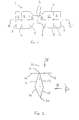
- the radiator consists of header tank having a base plate (50) of brass, which has plural holes in it for accepting a plurality of heat exchanger tubes (51, 52).
- the remainder of the header tank may be of brass or copper, or may be, for example, a plastic tank connected to the base plate via a gasket. It will be understood by one skilled in the art that a large number of such tubes will be provided in a typical radiator.
- the base plate (50) in the region immediately surrounding the holes has inwardly-directed (with respect to the interior of the header tank) flange portions (53).
- the holes may be non-circular, and are preferably oval or elliptical.
- Tubes (51, 52) of substantially uniform cross section are then inserted through the holes so that end regions of the tubes substantially coincide with the end portions of the flange regions (53) inside the header tank.
- the tubes are then expanded by a suitable mandrel so as to at least substantially conform with the inner periphery of the respective hole.
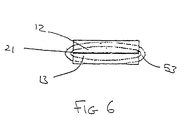
- the tube plug (1) may then be inserted into a desired tube, so that the engaging portion defined by regions (14, 15) engages the internal walls of the tube and the cap portion defined by end regions (12, 13) overlies the opening of the tube and the end of the flange region (53) to at least substantially close the tube.
- cap portion formed by end regions (12, 13) is seen to extend outwardly beyond the flange region and only a small region of the tube, proximate the ends of the throat portion (21) is uncovered by the cap portion of the tube plug.
- the assembly as a whole is then subject to fluxing and then to solder dipping.
- the solder dipping results in the unplugged tubes (51) being secured to the flange regions (53) of the header tank base (50) via the solder, the relatively narrow throat region (21) and the uncovered regions (60, 61) being filled by solder and the solder also bonds the cap portion (12, 13) being bonded to the ends of the flange regions (53) in a single operation.
- the tube plug has several advantages. Firstly there is no large mass of plug within the tube, and as a result tube (52) is not prevented from flexing during thermal contraction and expansion cycles as would be the case if the tube were plugged with solid solder.
- the tube plug significantly reduces the amount of solder consumed during the tube plugging operation. The solder which is consumed in tube plugging, using the tube plug, is only required to form a bond between two closely spaced surfaces, which is the application for which current solders are designed. There is thus no requirement to fill large gaps, which requirement in the prior art gives rise to deleterious structures and voids.
- a tube plug may be used to seal off the relevant tube for repair purposes. In that event, the tube plug is inserted into the desired tube as described above with reference to Figure 6, and the plug is then manually soldered in place.
- tube plug could be made of materials other than brass.
- heat exchanger could also be of other materials.
Landscapes
- Engineering & Computer Science (AREA)
- Physics & Mathematics (AREA)
- Thermal Sciences (AREA)
- Mechanical Engineering (AREA)
- General Engineering & Computer Science (AREA)
- Details Of Heat-Exchange And Heat-Transfer (AREA)
- Heat-Exchange Devices With Radiators And Conduit Assemblies (AREA)
Applications Claiming Priority (2)
| Application Number | Priority Date | Filing Date | Title |
|---|---|---|---|
| US08/500,601 US5823230A (en) | 1995-07-11 | 1995-07-11 | Heat exchanger assembly method and tube plug for heat exchanger |
| US500601 | 2000-02-08 |
Publications (2)
| Publication Number | Publication Date |
|---|---|
| EP0753714A2 true EP0753714A2 (de) | 1997-01-15 |
| EP0753714A3 EP0753714A3 (de) | 1997-12-29 |
Family
ID=23990131
Family Applications (1)
| Application Number | Title | Priority Date | Filing Date |
|---|---|---|---|
| EP96305078A Withdrawn EP0753714A3 (de) | 1995-07-11 | 1996-07-10 | Verfahren zum Zusammenbau eines Wärmetauschers und Rohrstopfen für Wärmetauscher |
Country Status (2)
| Country | Link |
|---|---|
| US (1) | US5823230A (de) |
| EP (1) | EP0753714A3 (de) |
Family Cites Families (13)
| Publication number | Priority date | Publication date | Assignee | Title |
|---|---|---|---|---|
| USRE15491E (en) * | 1922-11-21 | of natick | ||
| US3555656A (en) * | 1967-05-25 | 1971-01-19 | Westinghouse Electric Corp | Method of explosively plugging a leaky metal tube in a heat exchanger tube bundle |
| US3451583A (en) * | 1968-05-20 | 1969-06-24 | Lee Co | Expandable sealing plug |
| US3724062A (en) * | 1971-03-18 | 1973-04-03 | Westinghouse Electric Corp | Explosively welded plug for leaky tubes of a heat exchanger and method of using the same |
| US4178966A (en) * | 1978-02-13 | 1979-12-18 | Combustion Engineering, Inc. | Tube plug |
| US4245380A (en) * | 1978-11-01 | 1981-01-20 | Barber-Colman Company | Multiple heat pipe heat exchanger and method for making |
| US4502511A (en) * | 1983-01-03 | 1985-03-05 | Westinghouse Electric Corp. | Tube plug |
| US4637436A (en) * | 1983-11-15 | 1987-01-20 | Raychem Corporation | Annular tube-like driver |
| US4646816A (en) * | 1985-09-06 | 1987-03-03 | Samuel Rothstein | Simplified tube plugging |
| US4694863A (en) * | 1986-01-15 | 1987-09-22 | Cajon Company | Protective cap |
| US4787420A (en) * | 1986-12-01 | 1988-11-29 | Westinghouse Electric Corp. | Plugging apparatus and method using a hydraulically assisted plug expander |
| DE3716328C3 (de) * | 1987-05-15 | 1994-07-28 | Bbc Reaktor Gmbh | Hohlstopfen zum Verschließen eines Wärmetauscherrohres |
| US4844152A (en) * | 1987-09-03 | 1989-07-04 | Hummert Gerald F | Structural plug member and insert tool |
-
1995
- 1995-07-11 US US08/500,601 patent/US5823230A/en not_active Expired - Fee Related
-
1996
- 1996-07-10 EP EP96305078A patent/EP0753714A3/de not_active Withdrawn
Non-Patent Citations (1)
| Title |
|---|
| None |
Also Published As
| Publication number | Publication date |
|---|---|
| EP0753714A3 (de) | 1997-12-29 |
| US5823230A (en) | 1998-10-20 |
Similar Documents
| Publication | Publication Date | Title |
|---|---|---|
| KR100842337B1 (ko) | 열교환기 및 그 제조방법 | |
| US5785119A (en) | Heat exchanger and method for manufacturing the same | |
| US6938675B2 (en) | Heat exchanger | |
| US4744505A (en) | Method of making a heat exchanger | |
| US5749414A (en) | Connection between tubes and tube bottom for a heat exchanger | |
| EP0798531A1 (de) | Wärmetauscher und Verfahren zu seiner Herstellung | |
| US5067235A (en) | Method for joining heat exchanger tubes with headers | |
| US6883600B2 (en) | Heat exchanger with dual heat-exchanging portions | |
| US4858686A (en) | Heat exchanger | |
| US5366006A (en) | Tab joint between coolant tube and header | |
| KR100247888B1 (ko) | 열 교환기 | |
| US5214847A (en) | Method for manufacturing a heat exchanger | |
| US5358034A (en) | Heat exchanger | |
| EP0760457B1 (de) | Wärmetauscher | |
| US5823230A (en) | Heat exchanger assembly method and tube plug for heat exchanger | |
| US4258460A (en) | Method of making a heat exchanger | |
| JP2006289481A (ja) | 熱交換器およびその製造方法 | |
| US6276447B1 (en) | Apparatus formed by brazing and method for manufacturing the same | |
| CN1162109A (zh) | 热交换器及其制造方法 | |
| US7594327B2 (en) | Heat exchanger and method of making the same | |
| EP1068033B1 (de) | Verfahren zur herstellung einer flüssigkeitsdichten verbindung zwischen einem rohr und einem metallplattenteil | |
| CA1262125A (en) | Method of affixing tubes to headers in a heat exchanger and a heat exchanger assembly of tubes, headers, and fins | |
| US8839846B2 (en) | Mechanical joint for CuZnFe alloy heat exchanger and method | |
| JP4606230B2 (ja) | 熱交換器 | |
| JPS6314232Y2 (de) |
Legal Events
| Date | Code | Title | Description |
|---|---|---|---|
| PUAI | Public reference made under article 153(3) epc to a published international application that has entered the european phase |
Free format text: ORIGINAL CODE: 0009012 |
|
| AK | Designated contracting states |
Kind code of ref document: A2 Designated state(s): DE FR GB IT SE |
|
| PUAL | Search report despatched |
Free format text: ORIGINAL CODE: 0009013 |
|
| AK | Designated contracting states |
Kind code of ref document: A3 Designated state(s): DE FR GB IT SE |
|
| 17P | Request for examination filed |
Effective date: 19980522 |
|
| STAA | Information on the status of an ep patent application or granted ep patent |
Free format text: STATUS: THE APPLICATION IS DEEMED TO BE WITHDRAWN |
|
| 18D | Application deemed to be withdrawn |
Effective date: 20000201 |