EP0753391A1 - Elastomer extruding apparatus - Google Patents
Elastomer extruding apparatus Download PDFInfo
- Publication number
- EP0753391A1 EP0753391A1 EP96305126A EP96305126A EP0753391A1 EP 0753391 A1 EP0753391 A1 EP 0753391A1 EP 96305126 A EP96305126 A EP 96305126A EP 96305126 A EP96305126 A EP 96305126A EP 0753391 A1 EP0753391 A1 EP 0753391A1
- Authority
- EP
- European Patent Office
- Prior art keywords
- elastomer
- chamber
- extruding
- head
- finishing
- Prior art date
- Legal status (The legal status is an assumption and is not a legal conclusion. Google has not performed a legal analysis and makes no representation as to the accuracy of the status listed.)
- Granted
Links
Images


Classifications
-
- B—PERFORMING OPERATIONS; TRANSPORTING
- B29—WORKING OF PLASTICS; WORKING OF SUBSTANCES IN A PLASTIC STATE IN GENERAL
- B29C—SHAPING OR JOINING OF PLASTICS; SHAPING OF MATERIAL IN A PLASTIC STATE, NOT OTHERWISE PROVIDED FOR; AFTER-TREATMENT OF THE SHAPED PRODUCTS, e.g. REPAIRING
- B29C48/00—Extrusion moulding, i.e. expressing the moulding material through a die or nozzle which imparts the desired form; Apparatus therefor
- B29C48/03—Extrusion moulding, i.e. expressing the moulding material through a die or nozzle which imparts the desired form; Apparatus therefor characterised by the shape of the extruded material at extrusion
- B29C48/07—Flat, e.g. panels
- B29C48/08—Flat, e.g. panels flexible, e.g. films
-
- B—PERFORMING OPERATIONS; TRANSPORTING
- B29—WORKING OF PLASTICS; WORKING OF SUBSTANCES IN A PLASTIC STATE IN GENERAL
- B29C—SHAPING OR JOINING OF PLASTICS; SHAPING OF MATERIAL IN A PLASTIC STATE, NOT OTHERWISE PROVIDED FOR; AFTER-TREATMENT OF THE SHAPED PRODUCTS, e.g. REPAIRING
- B29C48/00—Extrusion moulding, i.e. expressing the moulding material through a die or nozzle which imparts the desired form; Apparatus therefor
- B29C48/16—Articles comprising two or more components, e.g. co-extruded layers
- B29C48/18—Articles comprising two or more components, e.g. co-extruded layers the components being layers
- B29C48/21—Articles comprising two or more components, e.g. co-extruded layers the components being layers the layers being joined at their surfaces
-
- B—PERFORMING OPERATIONS; TRANSPORTING
- B29—WORKING OF PLASTICS; WORKING OF SUBSTANCES IN A PLASTIC STATE IN GENERAL
- B29C—SHAPING OR JOINING OF PLASTICS; SHAPING OF MATERIAL IN A PLASTIC STATE, NOT OTHERWISE PROVIDED FOR; AFTER-TREATMENT OF THE SHAPED PRODUCTS, e.g. REPAIRING
- B29C48/00—Extrusion moulding, i.e. expressing the moulding material through a die or nozzle which imparts the desired form; Apparatus therefor
- B29C48/25—Component parts, details or accessories; Auxiliary operations
- B29C48/30—Extrusion nozzles or dies
- B29C48/305—Extrusion nozzles or dies having a wide opening, e.g. for forming sheets
- B29C48/307—Extrusion nozzles or dies having a wide opening, e.g. for forming sheets specially adapted for bringing together components, e.g. melts within the die
-
- B—PERFORMING OPERATIONS; TRANSPORTING
- B29—WORKING OF PLASTICS; WORKING OF SUBSTANCES IN A PLASTIC STATE IN GENERAL
- B29C—SHAPING OR JOINING OF PLASTICS; SHAPING OF MATERIAL IN A PLASTIC STATE, NOT OTHERWISE PROVIDED FOR; AFTER-TREATMENT OF THE SHAPED PRODUCTS, e.g. REPAIRING
- B29C48/00—Extrusion moulding, i.e. expressing the moulding material through a die or nozzle which imparts the desired form; Apparatus therefor
- B29C48/25—Component parts, details or accessories; Auxiliary operations
- B29C48/30—Extrusion nozzles or dies
- B29C48/35—Extrusion nozzles or dies with rollers
-
- B—PERFORMING OPERATIONS; TRANSPORTING
- B29—WORKING OF PLASTICS; WORKING OF SUBSTANCES IN A PLASTIC STATE IN GENERAL
- B29C—SHAPING OR JOINING OF PLASTICS; SHAPING OF MATERIAL IN A PLASTIC STATE, NOT OTHERWISE PROVIDED FOR; AFTER-TREATMENT OF THE SHAPED PRODUCTS, e.g. REPAIRING
- B29C48/00—Extrusion moulding, i.e. expressing the moulding material through a die or nozzle which imparts the desired form; Apparatus therefor
- B29C48/25—Component parts, details or accessories; Auxiliary operations
- B29C48/36—Means for plasticising or homogenising the moulding material or forcing it through the nozzle or die
- B29C48/49—Means for plasticising or homogenising the moulding material or forcing it through the nozzle or die using two or more extruders to feed one die or nozzle
-
- B—PERFORMING OPERATIONS; TRANSPORTING
- B29—WORKING OF PLASTICS; WORKING OF SUBSTANCES IN A PLASTIC STATE IN GENERAL
- B29L—INDEXING SCHEME ASSOCIATED WITH SUBCLASS B29C, RELATING TO PARTICULAR ARTICLES
- B29L2030/00—Pneumatic or solid tyres or parts thereof
Definitions
- the present invention relates to an elastomer extruding apparatus capable of forming elastomer products formed in multiple layers by plural extruders at high precision, and particularly intended for forming thin products.
- a multiplex extruding apparatus comprising two or more extruders is used.
- Such a multiplex extruding apparatus is disclosed, for example, in German patent number DE 3521643, wherein elastomer materials extruded from extruders discharges through one nozzle in order to form layers of a long band or sheet continuously.
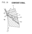
- United States Patent 4,683,095 discloses, as shown in Fig. 18, an apparatus provided with a roll at the extrusion end of the apparatus for enhancing product precision, especially the thickness precision.
- This apparatus has a convergent passage F in which elastomer materials E1, E2 extruded from two extruders are joined at a converging point P disposed in the midst of the die and moved forward while laminating, and a finishing chamber G composed of a tiny gap between a head H a and roller R0 which is provided at the down-stream side of the convergent passage F.
- an elastomer extruding apparatus comprising a head to which plural extruders for extruding elastomer material are linked, and a rotatable driven roller disposed at a front end of the head so as to form an extruding space between the roller and the front end of the head, wherein the head has a passage arrangement through which the elastomer materials extruded from extruders pass, said passage arrangement having an opening communicating with the extruding space, and the extruding space has a uniform chamber through which the elastomer materials flowed out from the opening pass while laminating and advance in the rotating direction together with the roller, and a finishing chamber communicating with the uniform chamber and forming the elastomer substantially into a final sectional shape by reducing the sectional height from the uniform chamber.
- the uniform chamber has a principal part substantially uniform in sectional shape and extending from the opening to the finishing chamber. Further, a length L of the principal part of the uniform chamber is preferably at least 1.5 times its sectional height T.
- the passage arrangement may comprise plural individual passages through which the elastomer materials from each extruders pass individually, and one converging passage extending from a convergent point of the plural individual passages and through which the elastomer materials from each individual passage passes while laminating together.
- the passage arrangement may comprise plural individual passages, through one of which the elastomer material from each extruder passes, opening into the extruding space individually.
- the principal part of the uniform chamber is formed between the finishing chamber and the opening closest to the finishing chamber among the openings of the plural individual passages.
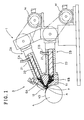
- an elastomer extruding apparatus 1 comprises, as shown in Fig. 1, plural, in this case two extruders 2A, 2B for extruding elastomer materials EA, EB, a head 3 to which the extruders 2A, 2B are coupled, and a roller 4 disposed at a small clearance from the head 3 so as to form an extruding space A between an outer circumference 4S of the roller 4 and a front end of the head 3.
- the two extruders 2A and 2B are structured alike, and are provided so that their centreline cross obliquely in a vertical plane, and each output end is fixed to the head 3.
- the extruders 2A, 2B are of conventional design for kneading and fusing the elastomer materials EA, EB fed from an injection port 21 by rotation of a screw shaft 23 driven through a gear reducer by a motor M toward the head 3.
- the head 3 comprises a base part 11 on which the extruders 2A, 2B are joined, and a die set 12 detachably fitted to the leading end of the base part 11.
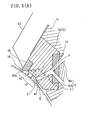
- the head 3 has a passage arrangement 5 communicating with the extruders 2A, 2B and extending forwards through the base part 11 and the die set 12, and the front of the passage arrangement 5 forms an opening 9 communicating with the extruding space A.
- the passage arrangement 5 in this embodiment comprises a first individual passage 6A connected to the first extruder 2A, a second individual passage 6B connected to the second extruder 2B, and a convergent passage 7 joining the individual passages 6A, 6B. Therefore, the elastomer materials EA, EB are mutually laminated together from a convergent point P in the die set 12, then they pass together through the convergent passage 7.
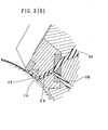
- Fig. 3 (B) shows the flow state of the elastomer materials in the extruding space A.
- the convergent point P and its vicinity are formed in a preformer die 13 fitted detachably to the rear end of a die main body 14.
- the extruding space A comprises a uniform chamber 17 in which the elastomer materials flowing out of the opening 9 advances in the rotating direction together with the roller 4, and a finishing chamber 16 consecutive to the uniform chamber 17 for forming the elastomer materials substantially into its final sectional shape.
- the finishing chamber 16 is a small gap portion formed between a finishing die 15 attached to the die main body 14 and the roller 4.
- an extruding end 10 for determining the product shape is fitted at the front edge of a slanted or sloping reducing portion 16A which decreases the sectional height in the rotating direction (extruding direction).
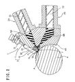
- a clasp 32 is provided to hold the die main body 14 and the finishing die 15 together in the base part 11 of the head 3.
- the clasp 32 is fitted, as shown in Fig. 2, to the leading end of a rod of a cylinder 31 affixed to the base part 11, and the clasp 32 is moved back and forth by forward and backward movement of the rod.
- the clasp 32 On forward movement of the rod, the clasp 32 abuts against the outward surfaces of the finishing die 15 and the die main body 14, and retains together both the finishing die 15 and the die main body 14.
- the die main body 14 can be dismounted together with the finishing die 15 and preformer die 13.
- the roller 4 has a columnar or straight part having a length exceeding the maximum width W in the axial direction of the extruding space A as shown in Fig. 6, and is set at a constant clearance from the die set 12.
- the columnar part is provided for the entire length of the roller 4, and hence the roller 4 is formed as a right circular cylinder.
- the roller 4 in this embodiment is driven and rotated in the counterclockwise direction, that is, to the left in Fig. 1.
- the uniform chamber 17 of the extruding space A has a principal part 18 provided between the edge e1, in the extruding direction, of the opening 9 and the reducing part 16A of the finishing chamber 16, and this principal part 18 is substantially uniform in sectional shape over the entire length.
- the elastomer material EA from the first individual passage 6A from the first extruder 2A and the elastomer material EB from the second individual passage 6B from the second extruder 2B are converged at the point P.
- the laminate material EF passes through the convergent passage 7, and is extruded from the opening 9 into the extruding space A.
- the elastomer product EG in this embodiment is a tire component, for example, an inner-liner rubber formed by laminating two kinds of elastomer material differing in properties, as shown in Fig. 8, to give an elastic body in a thin band form having a maximum thickness T0 of about 2.0 mm.
- the upper layer R is formed by the first extruder 2A, and the lower layer S by the second extruder 2B. Incidentally, if the volume of the lower layer S is greater as compared with the upper layer R, then the screw shaft 23 of the second extruder main body 2B is designed larger than that of the first extruder 2A.
- each passage 6A, 6B the sectional shape of each passage is varied downstream, and the elastomer materials EA, EB are thus both roughly formed while passing through their individual passages 6A and 6B.
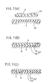
- Figs. 7(A), 7(B), 7(C) show changes of sectional shape of elastomer materials in each passage.
- Fig. 7(A) shows the sectional shape of the elastomer materials EA, EB when passing the inlet portion of the die set 12 of the individual passages 6A, 6B. At this time, the elastomer materials EA, EB are preformed in a sectional shape determined in consideration of the ratio of the thickness occupying in the product.
- Fig. 7 (B) shows the sectional shape of the elastomer materials EA, EB when passing the convergent passage 7.
- the elastomer materials EA, EB are laminated together by the internal pressure applied by the extruders, and hence the boundary surface Q of the laminate material EF is adhered strongly.
- Fig. 7 (C) shows the sectional shape of the laminate material EF in the uniform chamber 17, and in this embodiment it is nearly the same as the sectional shape at the opening 9 of the convergent passage 7.
- the laminate material EF moves being pulled the by rotation of the roller 4.
- the uniform chamber 17 has a uniform sectional shape and extends in the length L more than 1.5 times the sectional height T of the principal part 18, the force of resistance to passing from the other stationary side (upper side) is lessened while passing through the unfirom chamber 17.
- the feed speed between the elastomer materials EA, EB is nearly same, and the laminate material EF enters from the uniform chamber 17 into the finishing chamber 16 in a stable condition, so that distortion at the boundary surface Q is suppressed.
- the tensile force by the roller 4 acts over the entire length of the uniform chamber 17, and it provides pushing force.
- expansion of the elastomer product EG due to the reduction of pressure after extrusion from the extruding end 10 is reduced.
- shape changes due to this expansion are slight, and an elastomer product EG results of high quality excellent in dimensional precision and adhesive force between the laminations.
- This reduction of internal pressure of the apparatus also contributes to a reduction of internal temperature, so that and rubber scorching is prevented, material properties are maintained in favourable state, and dimensional stability is improved.
- the length L of the principal part 18 of the uniform chamber 17 is 1.5 or more times the sectional height T of the principal part 18, so as to provide an effective tensile force on the laminate material EF. If less than 1.5 times, such an effect is not found.
- the upper limit of the length L is preferred to be 150 mm or less. If greater, further improvement of the effect does not occur, but the head 3 becomes larger in size, and cost increases, and working efficiency drops. More preferably, it should be 100 mm or less.
- a bulge ( ⁇ ) is formed through a thin wall portion ( ⁇ ) at both sides in the width direction.
- the elastomer material passes through the finishing die 15, it is extruded into a shape including bulges ( ⁇ ), and thin wall portions ( ⁇ ) as indicated by single a dot chain line in Fig. 8, and by subsequently cutting off the thin wall portion ( ⁇ ) by a knife or other cutting tool, the width dimension of the elastomer product EG can be set precisely.
- the width dimension W ⁇ of the bulge ( ⁇ ) is preferred to be 5 to 25 mm. If it is less than 5 mm, it is likely to be torn off when removing the bulge ( ⁇ ), or if it exceeds 25 mm, the removed elastomer is large and the weight of the elastomer materials EA, EB increases when extruding, and hence it is disadvantageous to the working efficiency.
- the thickness t ⁇ of the thin wall portion ( ⁇ ) is preferred to be 2.5 mm or less in consideration of ease of cutting.
- the height t ⁇ of the bulge ( ⁇ ) is preferably 1.5 times to 5.0 times the thickness t- ⁇ , and if less than 1.5 times the thickness t ⁇ , the bulge ( ⁇ ) is likely to be torn off when removing, and if exceeding 5.0 times the thickness t ⁇ , the yield of the elastomer material increases, and the working efficiency drops.
- the reducing part 16A of the finishing chamber 16 may be formed with a steep slant or a step.
- FIG. 9 A second embodiment of the elastomer extruding apparatus 1 is illustrated in Fig. 9 to Fig. 15 (C).
- the passage arrangement 5 is composed only of the individual passages 26A, 26B for individually passing the elastomer materials EA, EB extruded from the extruders 2A, 2B.
- the individual passages 26A, 26B extend through the base part 11 and the die set 12, and openings 9A, 9B are formed at the front end so as to open against the roller 4 and communicate with the extruding space A.
- the die set 12 is composed of the die main body 14 forming the individual passages 26A, 26B and the uniform chamber 17, and the finishing die 15 for forming the finishing chamber 16.
- the uniform chamber 17 in the extruding space A has a principal part 18 between the opening closer to the finishing chamber 16 among the openings 9A, 9B, the opening 9A and the finishing chamber 16. More specifically, the principal part 18 is formed from the edge e1, in the extruding direction, of the opening 9A to the reducing part 16A the same as in the preceding embodiment, and this principal part 18 is substantially uniform in sectional shape over its entire length.
- the uniform chamber 17 has a guide path 30 for connecting the opening 9B and the principal part 18, between the convergent point P and opening 9B.
- the elastomer materials EA, EB extruded from the first and second extruders 2A, 2B pass through the individual passages 26A, 26B, and meet at the convergent point P in the uniform chamber 17, and then pass through the principal part 18 while laminating together.
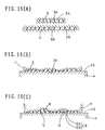
- Figs. 15(A), 15(B), 15(C) show the change of sectional shape of the elastomer materials in each passage.
- Fig. 15(A) shows the sectional shape at the inlet portion of the die main body 14.
- the elastomer materials EA, EB are formed in a flat rectangular section, and it is further reduced while passing through the die main body 14.
- Fig. 15(B) shows the sectional shape of the elastomer material EB when passing through the guide path 30.
- this guide path 30 it is preformed into a sectional shape determined in consideration of the ratio of the thickness of the elastomer materials EA, EB occupying in the product, that is, a shape similar to the sectional shape of the elastomer EB in the product.
- This preforming may be done at any position in the convergent point P, guide path 30, opening 9B, or near the leading end of the individual passage 26B if it is upsteam of the convergent point P.
- Fig. 15 (C) shows the sectional shape of the laminate material EF in the principal part 18.
- the elastomer material EB flowing in the guide path 30 is laminated with the elastomer material EA flowing in the first individual passage 26A.
- the sectional shape of the elastomer material EA is also preformed at the upstream of the convergent point P, for example, in the opening 9A or near the leading end of the individual passage 26A, and is then laminated.
- the preformed elastomer material EA is placed on the elastomer material EB and moved by the roller by passing through the guide path 30, and the laminate material EF is formed. That is, under the effect of the roller 4, the elastomer materials are laminated, and hence the distortion of the boundary surface Q is suppressed as compared with the case of placing the preliminarily joined laminate material EF under the effect of the roller 4.
- the uniform chamber 17 has a uniform sectional shape, the passing resistance received from the head 3 is lessened, and the feed speed of the elastomer materials EA, EB is nearly same, and moreover the changes of flow direction near the inlet of the finishing chamber 16 are also prevented, so that the distortion of the boundary surface Q may be further suppressed.
- the tensile force from the roller 4 also functions effective to assist the extruding force in the second embodiment, so that the internal pressure of the apparatus can be set low.
- the length L of the principal part 18 of the uniform chamber 17 is, as in the first embodiment, 1.5 or more of the sectional height T of the principal part 18, but the principal part 18 in this embodiment is not a rectangular shape as shown in Fig. 15 (C), and hence the maximum height of the section is taken as the sectional height T as shown in Fig. 13.
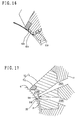
- FIG. 17 Another embodiment of the individual passages 26A, 26B is shown in Fig. 17.
- the first and second individual passages 26A, 26B are adjacent to each other without clearance at the convergent point P, and the guide path 30 is omitted.
- the elastomer material EB in the individual passage 26B precedes the elastomer material EA by at least a distance 35 so as to contact the roller 4, the elastomer material EB is moved, thereby suppressing distortion of the boundary surface Q.
Abstract
Description
- The present invention relates to an elastomer extruding apparatus capable of forming elastomer products formed in multiple layers by plural extruders at high precision, and particularly intended for forming thin products.
- To form elastomer products of multiple layers by laminating elastomer materials having different properties, a multiplex extruding apparatus comprising two or more extruders is used.
- Such a multiplex extruding apparatus is disclosed, for example, in German patent number DE 3521643, wherein elastomer materials extruded from extruders discharges through one nozzle in order to form layers of a long band or sheet continuously.
- When formed by using the apparatus of such constitution, however, for example, when forming thin elastomer products such as an inner-liner rubber for a pneumatic tire, it is difficult to obtain the dimensions and precision needed.
- On the other hand, United States Patent 4,683,095 discloses, as shown in Fig. 18, an apparatus provided with a roll at the extrusion end of the apparatus for enhancing product precision, especially the thickness precision.
- This apparatus has a convergent passage F in which elastomer materials E1, E2 extruded from two extruders are joined at a converging point P disposed in the midst of the die and moved forward while laminating, and a finishing chamber G composed of a tiny gap between a head H a and roller R0 which is provided at the down-stream side of the convergent passage F.
- In the converging passage F the two elastomers E1, E2 advance at nearly the same speed, but in the finishing chamber G, since the lower elastomer material E2 contacts the roller R0, it is pulled by the rotation of the roller R0, and fed at a faster speed V2 than the speed V1 of the upper elastomer E1.
- In particular, when the converging passage F and finishing chamber G are directly coupled, the flow direction changes abruptly near the inlet of the finishing chamber G, and the sectional area of the finishing chamber G becomes narrow, and hence the passing resistance receiving from the head H is increased. As a result, the speed difference further increases, and distortion occurs between the two elastomers E1 and E2, and a misalignment is likely to occur in the dimensions of the extruded products. In this apparatus, moreover, since the passing resistance is large, a relatively high pressure must be applied in order to extrude the elastomers from the finishing chamber G, and when the pressure difference inside and outside the apparatus is higher, the expansion of the elastomer after extruding increases, and hence product precision is spoiled.
- It is hence a primary object of the invention to provide an elastomer extruding apparatus which overcomes the above difficulties of the prior art which is capable of decreasing the passing resistance from the head, enhancing precision even in thin elastomer products, and forming products of high quality, maintaining stability of strength, without causing interlayer separation of elastomers.
- According to one aspect of the present invention, an elastomer extruding apparatus comprising a head to which plural extruders for extruding elastomer material are linked, and a rotatable driven roller disposed at a front end of the head so as to form an extruding space between the roller and the front end of the head, wherein the head has a passage arrangement through which the elastomer materials extruded from extruders pass, said passage arrangement having an opening communicating with the extruding space, and the extruding space has a uniform chamber through which the elastomer materials flowed out from the opening pass while laminating and advance in the rotating direction together with the roller, and a finishing chamber communicating with the uniform chamber and forming the elastomer substantially into a final sectional shape by reducing the sectional height from the uniform chamber.
- Preferably the uniform chamber has a principal part substantially uniform in sectional shape and extending from the opening to the finishing chamber. Further, a length L of the principal part of the uniform chamber is preferably at least 1.5 times its sectional height T.
- The passage arrangement may comprise plural individual passages through which the elastomer materials from each extruders pass individually, and one converging passage extending from a convergent point of the plural individual passages and through which the elastomer materials from each individual passage passes while laminating together.
- Also, the passage arrangement may comprise plural individual passages, through one of which the elastomer material from each extruder passes, opening into the extruding space individually. In this case, the principal part of the uniform chamber is formed between the finishing chamber and the opening closest to the finishing chamber among the openings of the plural individual passages.
- An embodiment of the present invention will now be described, by way of example, referring to the attached diagrammatic drawings, in which:
- Fig. 1 is a front view showing an elastomer extruding apparatus in a first embodiment of the invention;
- Fig. 2 is a sectional view showing a head and a roller;
- Fig. 3 (A) is a sectional view showing a passage arrangement and extruding space;
- Fig. 3 (B) is a sectional view showing the passage arrangement and extruding space together with elastomer materials;
- Fig. 4 is a perspective view showing a preformer die;
- Fig. 5 is a sectional view showing a uniform chamber;
- Fig. 6 is a perspective view showing a finishing chamber;
- Fig. 7 (A) is a sectional view showing a sectional shape of elastomer material in an individual passage;
- Fig. 7 (B) is a sectional view showing a sectional shape of elastomer material in a converging passage;
- Fig. 7 (C) is a sectional view showing a sectional shape of elastomer material in a uniform chamber;
- Fig. 8 is a sectional view showing an elastomer product formed by the apparatus;
- Fig. 9 is a front view showing an elastomer extruding apparatus in a second embodiment of the invention;
- Fig. 10 is a sectional view showing a head and a roller of the second embodiment;
- Fig. 11 (A) is a sectional view showing a passage arrangement and extruding space of the second embodiment;
- Fig. 11 (B) is a sectional view showing the passage arrangement and extruding space together with the elastomer materials of the second embodiment;
- Fig. 12 is a perspective view showing a die set of the second embodiment;
- Fig. 13 is a sectional view showing a uniform chamber of the second embodiment;
- Fig. 14 is a perspective view showing a finishing chamber of the second embodiment;
- Fig. 15 (A) is a sectional view showing a sectional shape of elastomer material in an individual passage of the second embodiment;
- Fig. 15 (B) is a sectional view showing a sectional shape of elastomer material in a guide passage of the second embodiment;
- Fig. 15 (C) is a sectional view showing a sectional shape of elastomer material in a uniform chamber of the second embodiment;
- Fig. 16 is a sectional view showing other embodiment of the finishing chamber;
- Fig. 17 is a sectional view showing other embodiment of the individual passage; and
- Fig. 18 is a sectional view showing a prior art.
- In the first embodiment of Figs. 1 to 7, an
elastomer extruding apparatus 1 comprises, as shown in Fig. 1, plural, in this case twoextruders head 3 to which theextruders roller 4 disposed at a small clearance from thehead 3 so as to form an extruding space A between anouter circumference 4S of theroller 4 and a front end of thehead 3. - The two
extruders head 3. Theextruders injection port 21 by rotation of ascrew shaft 23 driven through a gear reducer by a motor M toward thehead 3. - The
head 3 comprises abase part 11 on which theextruders die set 12 detachably fitted to the leading end of thebase part 11. As can be seen in Fig. 3(A) thehead 3 has apassage arrangement 5 communicating with theextruders base part 11 and thedie set 12, and the front of thepassage arrangement 5 forms anopening 9 communicating with the extruding space A. - The
passage arrangement 5 in this embodiment comprises a firstindividual passage 6A connected to thefirst extruder 2A, a secondindividual passage 6B connected to thesecond extruder 2B, and aconvergent passage 7 joining theindividual passages die set 12, then they pass together through theconvergent passage 7. - Thus the
individual passages base part 11, and the convergent point P andconvergent passage 7 are formed in the dieset 12. The extruding space A is formed between the dieset 12 and theroller 4. Fig. 3 (B) shows the flow state of the elastomer materials in the extruding space A. - The convergent point P and its vicinity are formed in a
preformer die 13 fitted detachably to the rear end of a diemain body 14. By this detachable structure of thepreformer die 13 it is easier to set the extruding shape and thus the dimensions of the elastomer materials EA, EB, and to adjust the pass-through speed in thepassages - The extruding space A comprises a
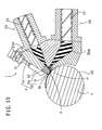
uniform chamber 17 in which the elastomer materials flowing out of the opening 9 advances in the rotating direction together with theroller 4, and afinishing chamber 16 consecutive to theuniform chamber 17 for forming the elastomer materials substantially into its final sectional shape. Thefinishing chamber 16 is a small gap portion formed between afinishing die 15 attached to the diemain body 14 and theroller 4. In this embodiment, anextruding end 10 for determining the product shape is fitted at the front edge of a slanted or sloping reducingportion 16A which decreases the sectional height in the rotating direction (extruding direction). - A
clasp 32 is provided to hold the diemain body 14 and the finishingdie 15 together in thebase part 11 of thehead 3. Theclasp 32 is fitted, as shown in Fig. 2, to the leading end of a rod of acylinder 31 affixed to thebase part 11, and theclasp 32 is moved back and forth by forward and backward movement of the rod. On forward movement of the rod, theclasp 32 abuts against the outward surfaces of thefinishing die 15 and the diemain body 14, and retains together both thefinishing die 15 and the diemain body 14. When the rod is half rectracted only the finishing die 15 can be dismounted. On fully retracting the rod, the diemain body 14 can be dismounted together with the finishing die 15 and preformer die 13. - The
roller 4 has a columnar or straight part having a length exceeding the maximum width W in the axial direction of the extruding space A as shown in Fig. 6, and is set at a constant clearance from thedie set 12. In this embodiment, the columnar part is provided for the entire length of theroller 4, and hence theroller 4 is formed as a right circular cylinder. Theroller 4 in this embodiment is driven and rotated in the counterclockwise direction, that is, to the left in Fig. 1. - Moreover, as shown in Fig. 3 (A), the
uniform chamber 17 of the extruding space A has aprincipal part 18 provided between the edge e1, in the extruding direction, of theopening 9 and the reducingpart 16A of the finishingchamber 16, and thisprincipal part 18 is substantially uniform in sectional shape over the entire length. - Therefore, the elastomer material EA from the first
individual passage 6A from thefirst extruder 2A and the elastomer material EB from the secondindividual passage 6B from thesecond extruder 2B are converged at the point P. At the downstream side of the convergent point P, after being laminated together, the laminate material EF passes through theconvergent passage 7, and is extruded from theopening 9 into the extruding space A. - The laminate material EF flowing into the extruding space A, in the mutually laminated state of the elastomer materials EA, EB, passes through the
uniform chamber 17, and is finally formed in the finishingchamber 16, thereby forming an elastomer product EG. - The elastomer product EG in this embodiment is a tire component, for example, an inner-liner rubber formed by laminating two kinds of elastomer material differing in properties, as shown in Fig. 8, to give an elastic body in a thin band form having a maximum thickness T0 of about 2.0 mm.
- The upper layer R is formed by the
first extruder 2A, and the lower layer S by thesecond extruder 2B. Incidentally, if the volume of the lower layer S is greater as compared with the upper layer R, then thescrew shaft 23 of the second extrudermain body 2B is designed larger than that of thefirst extruder 2A. - In the
individual passages individual passages - Figs. 7(A), 7(B), 7(C) show changes of sectional shape of elastomer materials in each passage.
- Fig. 7(A) shows the sectional shape of the elastomer materials EA, EB when passing the inlet portion of the die set 12 of the
individual passages - Fig. 7 (B) shows the sectional shape of the elastomer materials EA, EB when passing the
convergent passage 7. In theconvergent passage 7, the elastomer materials EA, EB are laminated together by the internal pressure applied by the extruders, and hence the boundary surface Q of the laminate material EF is adhered strongly. - Fig. 7 (C) shows the sectional shape of the laminate material EF in the
uniform chamber 17, and in this embodiment it is nearly the same as the sectional shape at theopening 9 of theconvergent passage 7. - Since one side (the lower side) of the
uniform chamber 17, as shown in Fig. 5, is formed by theouter circumference 4S of theroller 4, the laminate material EF moves being pulled the by rotation of theroller 4. At this time, since theuniform chamber 17 has a uniform sectional shape and extends in the length L more than 1.5 times the sectional height T of theprincipal part 18, the force of resistance to passing from the other stationary side (upper side) is lessened while passing through theunfirom chamber 17. As a result, the feed speed between the elastomer materials EA, EB is nearly same, and the laminate material EF enters from theuniform chamber 17 into the finishingchamber 16 in a stable condition, so that distortion at the boundary surface Q is suppressed. - The tensile force by the
roller 4 acts over the entire length of theuniform chamber 17, and it provides pushing force. As a result, while keeping the inner pressure of the apparatus low, it is possible to extrude the elastomer materials easily from the extrudingend 10. By reduction of internal pressure of the apparatus, moreover, expansion of the elastomer product EG due to the reduction of pressure after extrusion from the extrudingend 10 is reduced. Thus shape changes due to this expansion are slight, and an elastomer product EG results of high quality excellent in dimensional precision and adhesive force between the laminations. This reduction of internal pressure of the apparatus, also contributes to a reduction of internal temperature, so that and rubber scorching is prevented, material properties are maintained in favourable state, and dimensional stability is improved. - In this embodiment, the length L of the
principal part 18 of theuniform chamber 17 is 1.5 or more times the sectional height T of theprincipal part 18, so as to provide an effective tensile force on the laminate material EF. If less than 1.5 times, such an effect is not found. The upper limit of the length L is preferred to be 150 mm or less. If greater, further improvement of the effect does not occur, but thehead 3 becomes larger in size, and cost increases, and working efficiency drops. More preferably, it should be 100 mm or less. - Incidentally, in this embodiment, in the shape of the extruding
end 10 of the finishing die 15, as shown in Fig. 6, a bulge (α) is formed through a thin wall portion (β) at both sides in the width direction. - As the elastomer material passes through the finishing die 15, it is extruded into a shape including bulges (α), and thin wall portions (β) as indicated by single a dot chain line in Fig. 8, and by subsequently cutting off the thin wall portion (β) by a knife or other cutting tool, the width dimension of the elastomer product EG can be set precisely.
- The width dimension Wα of the bulge (α) is preferred to be 5 to 25 mm. If it is less than 5 mm, it is likely to be torn off when removing the bulge (α), or if it exceeds 25 mm, the removed elastomer is large and the weight of the elastomer materials EA, EB increases when extruding, and hence it is disadvantageous to the working efficiency.
- The thickness tβ of the thin wall portion (β) is preferred to be 2.5 mm or less in consideration of ease of cutting. The height tα of the bulge (α) is preferably 1.5 times to 5.0 times the thickness t-β, and if less than 1.5 times the thickness tβ, the bulge (α) is likely to be torn off when removing, and if exceeding 5.0 times the thickness tβ, the yield of the elastomer material increases, and the working efficiency drops.
- In this invention, in order that the tensile force from the
roller 4 may act appropriately so that the elastomer may pass the finishingchamber 16 easily, as shown in Fig. 16, the reducingpart 16A of the finishingchamber 16 may be formed with a steep slant or a step. - A second embodiment of the
elastomer extruding apparatus 1 is illustrated in Fig. 9 to Fig. 15 (C). - As shown in Fig. 11 (A), in the
elastomer extruding apparatus 1 in the second embodiment, thepassage arrangement 5 is composed only of theindividual passages extruders individual passages base part 11 and the die set 12, andopenings roller 4 and communicate with the extruding space A. - The die set 12 is composed of the die
main body 14 forming theindividual passages uniform chamber 17, and the finishing die 15 for forming the finishingchamber 16. - The
uniform chamber 17 in the extruding space A has aprincipal part 18 between the opening closer to the finishingchamber 16 among theopenings opening 9A and the finishingchamber 16. More specifically, theprincipal part 18 is formed from the edge e1, in the extruding direction, of theopening 9A to the reducingpart 16A the same as in the preceding embodiment, and thisprincipal part 18 is substantially uniform in sectional shape over its entire length. - Moreover, in the
uniform chamber 17, another edge e2 of theopening 9A forms a convergent point P where the elastomer materials EA, EB are converged. In this embodiment, by forming a clearance between theopenings uniform chamber 17 has aguide path 30 for connecting theopening 9B and theprincipal part 18, between the convergent point P andopening 9B. - Therefore, the elastomer materials EA, EB extruded from the first and
second extruders individual passages uniform chamber 17, and then pass through theprincipal part 18 while laminating together. - Figs. 15(A), 15(B), 15(C) show the change of sectional shape of the elastomer materials in each passage.
- Fig. 15(A) shows the sectional shape at the inlet portion of the die
main body 14. Herein, the elastomer materials EA, EB are formed in a flat rectangular section, and it is further reduced while passing through the diemain body 14. - Fig. 15(B) shows the sectional shape of the elastomer material EB when passing through the
guide path 30. In thisguide path 30, it is preformed into a sectional shape determined in consideration of the ratio of the thickness of the elastomer materials EA, EB occupying in the product, that is, a shape similar to the sectional shape of the elastomer EB in the product. This preforming may be done at any position in the convergent point P, guidepath 30,opening 9B, or near the leading end of theindividual passage 26B if it is upsteam of the convergent point P. - Fig. 15 (C) shows the sectional shape of the laminate material EF in the
principal part 18. At the convergent point P, the elastomer material EB flowing in theguide path 30 is laminated with the elastomer material EA flowing in the firstindividual passage 26A. The sectional shape of the elastomer material EA is also preformed at the upstream of the convergent point P, for example, in theopening 9A or near the leading end of theindividual passage 26A, and is then laminated. - Thus, in the second embodiment, the preformed elastomer material EA is placed on the elastomer material EB and moved by the roller by passing through the
guide path 30, and the laminate material EF is formed. That is, under the effect of theroller 4, the elastomer materials are laminated, and hence the distortion of the boundary surface Q is suppressed as compared with the case of placing the preliminarily joined laminate material EF under the effect of theroller 4. - Since the
uniform chamber 17 has a uniform sectional shape, the passing resistance received from thehead 3 is lessened, and the feed speed of the elastomer materials EA, EB is nearly same, and moreover the changes of flow direction near the inlet of the finishingchamber 16 are also prevented, so that the distortion of the boundary surface Q may be further suppressed. - As in the first embodiment, the tensile force from the
roller 4 also functions effective to assist the extruding force in the second embodiment, so that the internal pressure of the apparatus can be set low. - The length L of the
principal part 18 of theuniform chamber 17 is, as in the first embodiment, 1.5 or more of the sectional height T of theprincipal part 18, but theprincipal part 18 in this embodiment is not a rectangular shape as shown in Fig. 15 (C), and hence the maximum height of the section is taken as the sectional height T as shown in Fig. 13. - Another embodiment of the
individual passages individual passages guide path 30 is omitted. Also in this case, since the elastomer material EB in theindividual passage 26B precedes the elastomer material EA by at least adistance 35 so as to contact theroller 4, the elastomer material EB is moved, thereby suppressing distortion of the boundary surface Q.
Claims (8)
- An elastomer extruding apparatus comprising a head (3) to which plural extruders (2A,2B) for extruding elastomer material are linked, and a rotatable driven roller (4) disposed at a front end of the head (3) so as to form an extruding space (A) between the roller and the front end of the head (3), characterised in that the head (3) has a passage arrangement (5) through which the elastomer materials (EA,EB) extruded from extruders (2A,2B) pass, said passage arrangement (5) having an opening (9) communicating with the extruding space (A), and the extruding space (A) has a uniform chamber (17) through which the elastomer materials (EA,EB) flow out from the opening (9) pass while laminating and advance in the rotating direction together with the roller (4), and a finishing chamber (16) communicating with the uniform chamber (17) and forming the elastomer materials (EA,EB) substantially into a final sectional shape by reducing the sectional height from the uniform chamber (17).
- An elastomer extruding apparatus of claim 1, characterised in that the uniform chamber (17) has a principal part (18) substantially uniform in sectional shape and extending from the opening (9) to the finishing chamber (16).
- An elastomer extruding apparatus of claim 2, characterised in that the principal part (18) of the uniform chamber (17) has a length (L) at least 1.5 times the sectional height (T) of the principal part (18).
- An elastomer extruding apparatus of claim 1, 2 or 3, characterised in that the passage arrangement (5) of the head (3) comprises plural individual passages (6A,6B) through which the elastomer materials (EA,EB) extruded from each extruders (2A,2B) pass separately, and one convergent passage (7) extending from a convergent point (P) of the plural individual passages (6A,6B) and through which the elastomer materials (EA,EB) of the individual passages (6A,6B) pass while being laminated together.
- An elastomer extruding apparatus of claim 1, characterised in that the passage arrangement (5) of the head (3) comprises plural individual passages (26A,26B) through which the elastomer materials (EA,EB) extruded from each extruders (2A,2B) pass individually, each of the plural individual passages (26A,26B) having an opening (9A,9B) communicating with the extruding space (A), and the principal part (18) of the uniform chamber (17) is formed between the finishing chamber (16) and the opening (9A) closest to the finishing chamber (16) among the openings (9A,9B) of the plural individual passages (26A,26B).
- An elastomer extruding apparatus of claim 4, characterised in that the head (3) comprises a base part (11) for forming the individual passages ( 6A,6B) , and a die set (12) for forming the convergent point (P), convergent passage, and extruding space (A).
- An elastomer extruding apparatus of claim 6, characterised in that the die set (12) comprises a preformer die (13) for forming the convergent point (P), a die main body (14) for forming the convergent passage (7) and uniform chamber (17), and a finishing die (15) for forming the finishing chamber (16).
- An elastomer extruding apparatus of claim 5, characterised in that the head (3) comprises a base part (11) for forming the individual passages (26A,26B) and a die set (12) somprising a die main body (14) for forming a part of the individual passeges (26A,26B) and a uniform chamber (17), and a finishing die (15) for forming the finishing chamber (16).
Applications Claiming Priority (6)
| Application Number | Priority Date | Filing Date | Title |
|---|---|---|---|
| JP177674/95 | 1995-07-13 | ||
| JP17767395 | 1995-07-13 | ||
| JP177673/95 | 1995-07-13 | ||
| JP17767495 | 1995-07-13 | ||
| JP17767495 | 1995-07-13 | ||
| JP17767395 | 1995-07-13 |
Publications (2)
| Publication Number | Publication Date |
|---|---|
| EP0753391A1 true EP0753391A1 (en) | 1997-01-15 |
| EP0753391B1 EP0753391B1 (en) | 2001-09-19 |
Family
ID=26498149
Family Applications (1)
| Application Number | Title | Priority Date | Filing Date |
|---|---|---|---|
| EP96305126A Expired - Lifetime EP0753391B1 (en) | 1995-07-13 | 1996-07-11 | Elastomer extruding apparatus |
Country Status (3)
| Country | Link |
|---|---|
| US (1) | US5928679A (en) |
| EP (1) | EP0753391B1 (en) |
| DE (1) | DE69615294T2 (en) |
Cited By (11)
| Publication number | Priority date | Publication date | Assignee | Title |
|---|---|---|---|---|
| EP0868991A1 (en) * | 1997-04-03 | 1998-10-07 | PIRELLI COORDINAMENTO PNEUMATICI S.p.A. | Extrusion method and apparatus for manufacturing tread bands for vehicle tyres |
| WO1999038664A1 (en) * | 1998-01-29 | 1999-08-05 | The Goodyear Tire And Rubber Company | Extrudate shrinkage control and reduction |
| FR2775220A1 (en) * | 1998-02-26 | 1999-08-27 | Michelin & Cie | Electrically conductive heavy duty tire containing, e.g., silica filler |
| WO1999043506A1 (en) * | 1998-02-26 | 1999-09-02 | Compagnie Generale Des Etablissements Michelin - Michelin & Cie | Electrically conductive tyre and apparatus for extruding sections made conductive |
| WO2002092322A1 (en) * | 2001-05-16 | 2002-11-21 | Societe De Technologie Michelin | Instrumentation for co-extruding rubber mixtures |
| US6695606B1 (en) | 1998-01-29 | 2004-02-24 | The Goodyear Tire & Rubber Company | Extrudate shrinkage control and reduction |
| WO2004028779A1 (en) * | 2002-09-25 | 2004-04-08 | Societe De Technologie Michelin | Device for applying a rubbery mixture to a moving surface for producing tires |
| US6951233B1 (en) | 1998-02-26 | 2005-10-04 | Compagnie Generale Des Etablissements Michelin-Michelin & Cie | Electrically conductive tire and apparatus and process for extruding elements which have been made conductive |
| EP2669068A3 (en) * | 2012-05-31 | 2014-02-26 | Continental Reifen Deutschland GmbH | Method for producing a mixed sheet |
| CN104275456A (en) * | 2013-07-03 | 2015-01-14 | 程思明 | Technological process for continuous casting production line |
| WO2017146734A1 (en) * | 2016-02-26 | 2017-08-31 | Compagnie Generale Des Etablissements Michelin | Roller nose extruder with die plate for extrusion of multiple material product |
Families Citing this family (10)
| Publication number | Priority date | Publication date | Assignee | Title |
|---|---|---|---|---|
| EP1464467A2 (en) * | 2000-04-13 | 2004-10-06 | Ole-Bendt Rasmussen | Extruder with circular die for coextrusion |
| US7410604B2 (en) * | 2003-03-06 | 2008-08-12 | 3M Innovative Properties Company | Method of making retroreflective sheeting and slot die apparatus |
| US6821106B1 (en) * | 2003-06-24 | 2004-11-23 | The Goodyear Tire & Rubber Company | Roller die preformer for wide extrusions |
| US20050202113A1 (en) * | 2004-03-10 | 2005-09-15 | Cheng-Te Chi | Web bonded plastic sheet extruding system |
| DE102005020432B4 (en) * | 2005-04-29 | 2009-09-03 | Troester Gmbh & Co. Kg | Device for producing a profile |
| EP2147770B1 (en) * | 2007-03-27 | 2017-06-21 | Bridgestone Corporation | Unvulcanized rubber extruder and process for producing unvulcanized rubber |
| FR2922808B1 (en) * | 2007-10-30 | 2010-02-19 | Michelin Soc Tech | DEVICE FOR THE EXTRUSION OF A GUM BAND. |
| JP6324846B2 (en) * | 2014-08-26 | 2018-05-16 | 東洋ゴム工業株式会社 | Rubber member manufacturing apparatus and manufacturing method |
| DE102016121262B3 (en) * | 2016-11-07 | 2018-02-22 | Troester Gmbh & Co. Kg | extrusion device |
| FR3086198B1 (en) * | 2018-09-20 | 2022-01-28 | Michelin & Cie | COEXTRUSION MACHINE FOR ELASTOMERIC BLENDS |
Citations (4)
| Publication number | Priority date | Publication date | Assignee | Title |
|---|---|---|---|---|
| GB1230869A (en) * | 1967-11-02 | 1971-05-05 | ||
| US3871810A (en) * | 1972-11-20 | 1975-03-18 | Uniroyal Inc | Extruder and roller-die combination |
| US4526528A (en) * | 1984-06-28 | 1985-07-02 | The Goodyear Tire & Rubber Company | Apparatus for forming a co-extrusion from extruded strips |
| US4683095A (en) * | 1985-05-08 | 1987-07-28 | The Uniroyal Goodrich Tire Company | Early progressive junction extrusion process and system |
Family Cites Families (6)
| Publication number | Priority date | Publication date | Assignee | Title |
|---|---|---|---|---|
| EP0111728A3 (en) * | 1982-11-12 | 1985-04-03 | Concast Standard Ag | Method of and device for producing products in the shape of strips or foils |
| US4539169A (en) * | 1983-07-29 | 1985-09-03 | The Goodyear Tire & Rubber Company | Apparatus and method for forming a co-extrusion from extruded strips |
| JPS61258724A (en) * | 1985-05-14 | 1986-11-17 | Bridgestone Corp | Variable contour rubber extruding device |
| DE3521643C1 (en) * | 1985-06-15 | 1986-07-03 | Hermann Berstorff Maschinenbau Gmbh, 3000 Hannover | Hinged extrusion head for the production of rubber or plastic flat profiles |
| JP2559249B2 (en) * | 1988-03-30 | 1996-12-04 | 株式会社ブリヂストン | Spindle type extruder switch |
| JP3124561B2 (en) * | 1991-02-01 | 2001-01-15 | 株式会社ブリヂストン | Rubber sheet member for tire |
-
1996
- 1996-07-11 EP EP96305126A patent/EP0753391B1/en not_active Expired - Lifetime
- 1996-07-11 DE DE69615294T patent/DE69615294T2/en not_active Expired - Fee Related
- 1996-07-11 US US08/678,702 patent/US5928679A/en not_active Expired - Fee Related
Patent Citations (4)
| Publication number | Priority date | Publication date | Assignee | Title |
|---|---|---|---|---|
| GB1230869A (en) * | 1967-11-02 | 1971-05-05 | ||
| US3871810A (en) * | 1972-11-20 | 1975-03-18 | Uniroyal Inc | Extruder and roller-die combination |
| US4526528A (en) * | 1984-06-28 | 1985-07-02 | The Goodyear Tire & Rubber Company | Apparatus for forming a co-extrusion from extruded strips |
| US4683095A (en) * | 1985-05-08 | 1987-07-28 | The Uniroyal Goodrich Tire Company | Early progressive junction extrusion process and system |
Non-Patent Citations (1)
| Title |
|---|
| W. MAY: "Das Einwalzenkopf-System EWK - eine neue Technologie in der Kautschukverarbeitung", KAUTSCHUK UND GUMMI, vol. 37, no. 6, June 1984 (1984-06-01), HEIDELBERG DE, pages 505 - 508, XP002015848 * |
Cited By (17)
| Publication number | Priority date | Publication date | Assignee | Title |
|---|---|---|---|---|
| US6495081B2 (en) | 1997-04-03 | 2002-12-17 | Pirelli Coordinamento Pneumatici | Method for manufacturing tread bands for vehicle tires |
| US6866495B2 (en) | 1997-04-03 | 2005-03-15 | Pirelli Coordinamento Pneumatici S.P.A. | Apparatus for manufacturing tread bands for vehicle tires |
| EP0868991A1 (en) * | 1997-04-03 | 1998-10-07 | PIRELLI COORDINAMENTO PNEUMATICI S.p.A. | Extrusion method and apparatus for manufacturing tread bands for vehicle tyres |
| WO1999038664A1 (en) * | 1998-01-29 | 1999-08-05 | The Goodyear Tire And Rubber Company | Extrudate shrinkage control and reduction |
| US6695606B1 (en) | 1998-01-29 | 2004-02-24 | The Goodyear Tire & Rubber Company | Extrudate shrinkage control and reduction |
| WO1999043506A1 (en) * | 1998-02-26 | 1999-09-02 | Compagnie Generale Des Etablissements Michelin - Michelin & Cie | Electrically conductive tyre and apparatus for extruding sections made conductive |
| EP1095798A1 (en) * | 1998-02-26 | 2001-05-02 | Compagnie Générale des Etablissements MICHELIN-MICHELIN & CIE | Apparatus for extruding sections made conductive |
| WO1999043505A1 (en) * | 1998-02-26 | 1999-09-02 | Compagnie Generale Des Etablissements Michelin - Michelin & Cie | Electrically conductive tyre and apparatus for extruding a section with conductive insert |
| US6834693B1 (en) | 1998-02-26 | 2004-12-28 | Compagnie Generle Des Etablissements Michelin-Michelin & Cie | Electrically conductive tire and extrusion equipment for a section with a conductive insert |
| FR2775220A1 (en) * | 1998-02-26 | 1999-08-27 | Michelin & Cie | Electrically conductive heavy duty tire containing, e.g., silica filler |
| US6951233B1 (en) | 1998-02-26 | 2005-10-04 | Compagnie Generale Des Etablissements Michelin-Michelin & Cie | Electrically conductive tire and apparatus and process for extruding elements which have been made conductive |
| WO2002092322A1 (en) * | 2001-05-16 | 2002-11-21 | Societe De Technologie Michelin | Instrumentation for co-extruding rubber mixtures |
| US6994817B2 (en) | 2001-05-16 | 2006-02-07 | Michelin Recherche Et Technique S.A. | Process and apparatus for the coextrusion of rubber mixtures |
| WO2004028779A1 (en) * | 2002-09-25 | 2004-04-08 | Societe De Technologie Michelin | Device for applying a rubbery mixture to a moving surface for producing tires |
| EP2669068A3 (en) * | 2012-05-31 | 2014-02-26 | Continental Reifen Deutschland GmbH | Method for producing a mixed sheet |
| CN104275456A (en) * | 2013-07-03 | 2015-01-14 | 程思明 | Technological process for continuous casting production line |
| WO2017146734A1 (en) * | 2016-02-26 | 2017-08-31 | Compagnie Generale Des Etablissements Michelin | Roller nose extruder with die plate for extrusion of multiple material product |
Also Published As
| Publication number | Publication date |
|---|---|
| DE69615294T2 (en) | 2002-04-18 |
| EP0753391B1 (en) | 2001-09-19 |
| DE69615294D1 (en) | 2001-10-25 |
| US5928679A (en) | 1999-07-27 |
Similar Documents
| Publication | Publication Date | Title |
|---|---|---|
| EP0753391B1 (en) | Elastomer extruding apparatus | |
| EP0174260B1 (en) | Roller die extrusion apparatus for the co-extrusion of plastics | |
| JP4759563B2 (en) | Method for continuously producing a double wall tube with socket, double wall tube, and apparatus for carrying out the method and producing the double wall tube | |
| EP0139604B1 (en) | Apparatus and method for making a band from strips | |
| AU2001262244B2 (en) | Method and apparatus for joining sheet- or ribbon formed flows in a coextrusion process | |
| AU2001262244A1 (en) | Method and apparatus for joining sheet- or ribbon formed flows in a coextrusion process | |
| US6190595B1 (en) | Extrusion arrangement | |
| JPH0155088B2 (en) | ||
| EP0703054B1 (en) | Method of and apparatus for forming weather strip by extrusion | |
| US4826422A (en) | Restriction insert for an extrusion die | |
| JPH06262663A (en) | Extruding device and method for unvulcanized rubber mixture | |
| US5673612A (en) | Coextruding extruder especially for foodstuffs such as paste and stuffing | |
| US20060105072A1 (en) | Polymer processing system including compression chamber and method for using same | |
| US20090136608A1 (en) | Apparatus for continuous production of a composite pipe with a pipe socket | |
| US5698235A (en) | Extrusion screw for extruder | |
| EP0280518B1 (en) | An apparatus for quantitatively extruding food material | |
| JP3358942B2 (en) | Elastomer extrusion equipment | |
| EP1211049B1 (en) | Method and apparatus for rubber extrusion | |
| EP3453508A1 (en) | Extruder feeding assembly and extruder apparatus incorporating it | |
| JP3378736B2 (en) | Elastomer extrusion equipment | |
| EP3508324B1 (en) | Co-extrusion plant and method | |
| CN116394557B (en) | Preparation method and processing equipment of high-permeability full-plastic sheet | |
| ZA200208221B (en) | Method and apparatus for joining sheet- or ribbon formed flows in a coextrusion process. | |
| EP3769930A1 (en) | Method and plant for the production of three-layer panels in thermoplastic material | |
| CN116533516A (en) | 3D printer nozzle and 3D printing equipment |
Legal Events
| Date | Code | Title | Description |
|---|---|---|---|
| PUAI | Public reference made under article 153(3) epc to a published international application that has entered the european phase |
Free format text: ORIGINAL CODE: 0009012 |
|
| AK | Designated contracting states |
Kind code of ref document: A1 Designated state(s): DE FR GB |
|
| 17P | Request for examination filed |
Effective date: 19970303 |
|
| 17Q | First examination report despatched |
Effective date: 19990722 |
|
| GRAG | Despatch of communication of intention to grant |
Free format text: ORIGINAL CODE: EPIDOS AGRA |
|
| RIN1 | Information on inventor provided before grant (corrected) |
Inventor name: YAMAMORI, SHUICHI Inventor name: OOKI, MASAHIKO |
|
| GRAG | Despatch of communication of intention to grant |
Free format text: ORIGINAL CODE: EPIDOS AGRA |
|
| GRAH | Despatch of communication of intention to grant a patent |
Free format text: ORIGINAL CODE: EPIDOS IGRA |
|
| GRAH | Despatch of communication of intention to grant a patent |
Free format text: ORIGINAL CODE: EPIDOS IGRA |
|
| GRAA | (expected) grant |
Free format text: ORIGINAL CODE: 0009210 |
|
| AK | Designated contracting states |
Kind code of ref document: B1 Designated state(s): DE FR GB |
|
| REF | Corresponds to: |
Ref document number: 69615294 Country of ref document: DE Date of ref document: 20011025 |
|
| REG | Reference to a national code |
Ref country code: GB Ref legal event code: IF02 |
|
| ET | Fr: translation filed | ||
| PLBE | No opposition filed within time limit |
Free format text: ORIGINAL CODE: 0009261 |
|
| STAA | Information on the status of an ep patent application or granted ep patent |
Free format text: STATUS: NO OPPOSITION FILED WITHIN TIME LIMIT |
|
| 26N | No opposition filed | ||
| PGFP | Annual fee paid to national office [announced via postgrant information from national office to epo] |
Ref country code: DE Payment date: 20080717 Year of fee payment: 13 |
|
| PGFP | Annual fee paid to national office [announced via postgrant information from national office to epo] |
Ref country code: FR Payment date: 20080718 Year of fee payment: 13 |
|
| PGFP | Annual fee paid to national office [announced via postgrant information from national office to epo] |
Ref country code: GB Payment date: 20080716 Year of fee payment: 13 |
|
| GBPC | Gb: european patent ceased through non-payment of renewal fee |
Effective date: 20090711 |
|
| REG | Reference to a national code |
Ref country code: FR Ref legal event code: ST Effective date: 20100331 |
|
| PG25 | Lapsed in a contracting state [announced via postgrant information from national office to epo] |
Ref country code: FR Free format text: LAPSE BECAUSE OF NON-PAYMENT OF DUE FEES Effective date: 20090731 |
|
| PG25 | Lapsed in a contracting state [announced via postgrant information from national office to epo] |
Ref country code: GB Free format text: LAPSE BECAUSE OF NON-PAYMENT OF DUE FEES Effective date: 20090711 |
|
| PG25 | Lapsed in a contracting state [announced via postgrant information from national office to epo] |
Ref country code: DE Free format text: LAPSE BECAUSE OF NON-PAYMENT OF DUE FEES Effective date: 20100202 |