EP0753351A2 - Liquid vaporizer with filler plug - Google Patents
Liquid vaporizer with filler plug Download PDFInfo
- Publication number
- EP0753351A2 EP0753351A2 EP96108525A EP96108525A EP0753351A2 EP 0753351 A2 EP0753351 A2 EP 0753351A2 EP 96108525 A EP96108525 A EP 96108525A EP 96108525 A EP96108525 A EP 96108525A EP 0753351 A2 EP0753351 A2 EP 0753351A2
- Authority
- EP
- European Patent Office
- Prior art keywords
- casing
- plug
- vaporizer
- liquid
- hole
- Prior art date
- Legal status (The legal status is an assumption and is not a legal conclusion. Google has not performed a legal analysis and makes no representation as to the accuracy of the status listed.)
- Granted
Links
- 239000006200 vaporizer Substances 0.000 title claims abstract description 21
- 239000007788 liquid Substances 0.000 title claims description 10
- 239000000945 filler Substances 0.000 title 1
- 230000000903 blocking effect Effects 0.000 claims description 3
- 230000002093 peripheral effect Effects 0.000 claims 1
- 239000012263 liquid product Substances 0.000 abstract description 8
- 239000002991 molded plastic Substances 0.000 abstract 1
- 239000000047 product Substances 0.000 description 12
- 230000006835 compression Effects 0.000 description 4
- 238000007906 compression Methods 0.000 description 4
- 239000002304 perfume Substances 0.000 description 3
- 244000273618 Sphenoclea zeylanica Species 0.000 description 2
- 238000005086 pumping Methods 0.000 description 2
- 230000004323 axial length Effects 0.000 description 1
- 230000003247 decreasing effect Effects 0.000 description 1
- 238000001704 evaporation Methods 0.000 description 1
- 239000000463 material Substances 0.000 description 1
- 239000002184 metal Substances 0.000 description 1
- 238000000034 method Methods 0.000 description 1
- 230000000717 retained effect Effects 0.000 description 1
- 239000007921 spray Substances 0.000 description 1
- 230000007704 transition Effects 0.000 description 1
Images

Classifications
-
- B—PERFORMING OPERATIONS; TRANSPORTING
- B05—SPRAYING OR ATOMISING IN GENERAL; APPLYING FLUENT MATERIALS TO SURFACES, IN GENERAL
- B05B—SPRAYING APPARATUS; ATOMISING APPARATUS; NOZZLES
- B05B11/00—Single-unit hand-held apparatus in which flow of contents is produced by the muscular force of the operator at the moment of use
- B05B11/0005—Components or details
- B05B11/0037—Containers
- B05B11/0056—Containers with an additional opening for filling or refilling
-
- B—PERFORMING OPERATIONS; TRANSPORTING
- B05—SPRAYING OR ATOMISING IN GENERAL; APPLYING FLUENT MATERIALS TO SURFACES, IN GENERAL
- B05B—SPRAYING APPARATUS; ATOMISING APPARATUS; NOZZLES
- B05B11/00—Single-unit hand-held apparatus in which flow of contents is produced by the muscular force of the operator at the moment of use
- B05B11/0005—Components or details
- B05B11/0037—Containers
Definitions
- This invention relates to a vaporizer of very small dimensions, to be disposed of after the contained dose of liquid product has been consumed. It comprises a casing to contain the product to be vaporized, for example perfume, and an atomizing pump for evaporating the product.
- Conventional vaporizers comprise a container provided with an opening through which a metered quantity of liquid product is fed. When filling is complete the opening is closed by mounting the atomizing pump thereon, this being retained in place by forcing, by a thread or by clinching a metal cap.
- the main drawback of this procedure is that in addition to carrying out the filling, the purchaser of the vaporizer, who is generally the perfume producer, has to manipulate and mount the pump with the container full, with the risk of spilling the product and in any event requiring machines of a certain complexity.
- An object of the present invention is to provide a small dimension vaporizer which can be filled with the product dose after the pump has been mounted.
- the atomizing pump used in the vaporizer of the invention can be of any known type. It can therefore be either of the types described hereinafter or of the types described for example in USA patents 4,896,799 and 5,002,207.
- the reference numeral 1 indicates the cylindrical casing of the vaporizer.
- the cylindrical casing comprises two spaced-apart annular projections 2, 3 on its upper part.
- the upper annular projection 2 is positioned a certain distance from the upper end 1A of the casing and is shaped as a lead-in.
- the lower projection 3 is formed as a flat step of transition from one thickness to another greater thickness of the inner wall of the casing.
- An annular guide member 4 having a central hole 5 and a partially annular internal compartment 6 connected to said hole is positioned between the two projections.
- an annular depression 7 in which there engages the outer end 8 of a tubular member 9 comprising, from the top downwards, four sections 10, 11, 12, 13 of decreasing diameter.
- the first section 10 forms the cylinder for an axially hollow first piston 14 provided with elastic seal lips 15 and an axially hollow stem 16 on which a conventional dispensing cap 17 carrying a usual spray nozzle 18 is forced.
- the skirt 22 with its lower edge 23 and the interior contour of the second section 11 form the suction valve.
- the third section 12 of the tubular member acts as a spring guide, the lower end of the compression spring 20 acting on its bottom step.
- the fourth section 13 acts as a dip tube for the liquid.
- the wall 24 In the lower part of the casing 1, at a certain distance from its lower end 1B, there is a transverse wall 24 bounding the compartment 1C in which the liquid product to be dispensed is placed.
- the wall 24 comprises a hole 25 in an eccentric position and a downwardly extending projection 26 in a central position.
- the projection 26 is surrounded at a certain distance by a downwardly extending concentric cylindrical skirt 27. This skirt extends to a distance D from the lower end 1B of the casing 1.
- Said hole 25 opens into the interspace 28 between the projection 26 and the skirt 27.
- a plug 29 provided with an axial hole 30 and a head 31, its height being slightly less than D so that when the plug is completely inserted ( Figure 2) it does not project from the lower end 1B of the casing 1.
- the vaporizer is supplied by the manufacturer to the purchaser who is required to fill it with the liquid product when in the configuration of Figure 1 (ie with the pump mounted), in which the plug 29 is only partially inserted so as to leave a passage between its hole 30 and the hole 25 provided in the transverse wall 24, this passage enabling the product to be loaded into the vaporizer through the plug. Having loaded the required dose of product, the plug 29 is pressed right down ( Figure 2) so that its hole 30 becomes engaged by the projection 26, so sealedly blocking said passage.
- the base wall 24A comprises a central hole 25A.
- the projection which in Figures 1 and 2 forms part of the base wall 24A is provided on the plug and is indicated by 26A.
- the purpose of the projection 26A is to block the hole 25A when the plug 29A is pushed right down (see Figure 4).
- the plug which is of a softer material than the casing 1A, has a series of passages 30A provided angularly spaced apart and opening into a flared hole 50 present in the head 31A.
- the atomizing pumps of Figures 3 and 4 are identical and comprise the tubular member 9A which in this case has three zones 10A, 11A and 12A of different diameter.
- a piston 51 comprising a dead axial liquid exit hole 52 into which there open radial passages 53 which, when the pump is in the position shown in the figure, are blocked by an annular gasket 54.
- the piston also comprises a lower projection 55 subjected to the thrust of a compression spring 56.
- a ball 57 acts as the suction valve.
- a dip tube 58 In the embodiment of Figure 3, within the smallest-diameter section 12A of the member 9A there is mounted a dip tube 58.
- the dip tube In the embodiment of Figure 4 the dip tube is replaced by a bowl 59 located at the level of the third section 12A and surrounding this latter at a certain distance therefrom. The bowl is forced into the casing 1A and peripherally comprises axial channels 60.
- the embodiment of Figure 4 takes account of the fact that because vaporizers used for perfume and the like are long and narrow they have difficulty in remaining upright, and assume a horizontal position in handbags with possible resultant difficulty in dispensing the product.
- the bowl 59 is filled via the channel 60 when the vaporizer is horizontal, and can hence quickly dispense the product when the cap 17A is pressed.
- This embodiment also enables container casings 1A of different lengths (and hence capacities) to be used without having to provide the pump with a dip tube of adequate length.
- the liquid product trapped between the piston 51 and ball 57 is pressurized and is dispensed when the radial apertures 53 disengage from the gasket 54 which is located in an annular groove of piston 51 where the radial holes 53 emerge, the annular groove having such an axial length that on the pumping stroke the gasket moves upwards in the groove freeing the radial holes and viceversa in the opposite stroke.
- the vacuum which is produced causes new product to flow through the suction valve (ball 57).
Abstract
Description
- This invention relates to a vaporizer of very small dimensions, to be disposed of after the contained dose of liquid product has been consumed. It comprises a casing to contain the product to be vaporized, for example perfume, and an atomizing pump for evaporating the product.
- Conventional vaporizers comprise a container provided with an opening through which a metered quantity of liquid product is fed. When filling is complete the opening is closed by mounting the atomizing pump thereon, this being retained in place by forcing, by a thread or by clinching a metal cap. The main drawback of this procedure is that in addition to carrying out the filling, the purchaser of the vaporizer, who is generally the perfume producer, has to manipulate and mount the pump with the container full, with the risk of spilling the product and in any event requiring machines of a certain complexity.
- An object of the present invention is to provide a small dimension vaporizer which can be filled with the product dose after the pump has been mounted.
- This and further objects which will be apparent from the detailed description given hereinafter are attained by a vaporizer in accordance with the accompanying claims.
- The invention will be more apparent from the description thereof given hereinafter by way of non-limiting example with reference to the accompanying drawing, in which:
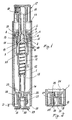
- Figure 1 is an axial section through a vaporizer with its plug mounted in the position which allows product filling; the manufacturer supplies the vaporizer in this configuration to the firm which is to fill it with the product;
- Figure 2 is a detailed section showing the plug in its closed position, ie when filling is complete;
- Figure 3 is an axial section through a modified vaporizer;
- Figure 4 is an axial section through a further modified vaporizer.
- It should firstly be noted that the atomizing pump used in the vaporizer of the invention can be of any known type. It can therefore be either of the types described hereinafter or of the types described for example in USA patents 4,896,799 and 5,002,207.
- In the figures the reference numeral 1 indicates the cylindrical casing of the vaporizer.
- The cylindrical casing comprises two spaced-apart
annular projections - The upper
annular projection 2 is positioned a certain distance from theupper end 1A of the casing and is shaped as a lead-in. - The
lower projection 3 is formed as a flat step of transition from one thickness to another greater thickness of the inner wall of the casing. - An annular guide member 4 having a central hole 5 and a partially annular internal compartment 6 connected to said hole is positioned between the two projections. In the wall of the annular compartment there is provided an annular depression 7 in which there engages the
outer end 8 of a tubular member 9 comprising, from the top downwards, foursections first section 10 forms the cylinder for an axially hollowfirst piston 14 provided withelastic seal lips 15 and an axiallyhollow stem 16 on which a conventional dispensingcap 17 carrying ausual spray nozzle 18 is forced. - Within the
stem 16 there is aconstriction 19 against which avalving element 21 adheres, urged by acompression spring 20. The valving element and the cooperating constriction form the delivery valve of the vaporizer pump, this pump comprising saidpiston 14. - With the
valving element 21 there is rigid an annular skirt 22 within which the upper end of thecompression spring 20 is positioned. During the pumping movement, the skirt 22 penetrates into thesecond section 11 of the tubular member 9, and slides in a sealed manner therein. - The skirt 22 with its
lower edge 23 and the interior contour of thesecond section 11 form the suction valve. - The
third section 12 of the tubular member acts as a spring guide, the lower end of thecompression spring 20 acting on its bottom step. - The
fourth section 13 acts as a dip tube for the liquid. - In the lower part of the casing 1, at a certain distance from its
lower end 1B, there is atransverse wall 24 bounding the compartment 1C in which the liquid product to be dispensed is placed. Thewall 24 comprises ahole 25 in an eccentric position and a downwardly extendingprojection 26 in a central position. Theprojection 26 is surrounded at a certain distance by a downwardly extending concentriccylindrical skirt 27. This skirt extends to a distance D from thelower end 1B of the casing 1. Saidhole 25 opens into theinterspace 28 between theprojection 26 and theskirt 27. - Within the
skirt 27 there is sealedly mounted aplug 29 provided with anaxial hole 30 and ahead 31, its height being slightly less than D so that when the plug is completely inserted (Figure 2) it does not project from thelower end 1B of the casing 1. - The vaporizer is supplied by the manufacturer to the purchaser who is required to fill it with the liquid product when in the configuration of Figure 1 (ie with the pump mounted), in which the
plug 29 is only partially inserted so as to leave a passage between itshole 30 and thehole 25 provided in thetransverse wall 24, this passage enabling the product to be loaded into the vaporizer through the plug. Having loaded the required dose of product, theplug 29 is pressed right down (Figure 2) so that itshole 30 becomes engaged by theprojection 26, so sealedly blocking said passage. - With regard to the pump operation, it should firstly be noted that when in the blocked position of Figure 1, between the
valving element 21 and part of the skirt 22 on one side and thepiston 14 on the other side there is an interspace 40. It will now be assumed that the product is to be dispensed. Thecap 17 is pressed downwards by the user. Thepiston 14 moves downwards as does thevalving element 21 with the skirt 22, which passes into thesecond section 11 of the member 9. Because of the difference in the diameters of thefirst section 10 and thesecond section 11 of the tubular member 9, at a certain moment the pressure of the liquid trapped between thepiston 14 and thevalving element 21 plus skirt 22 overcomes the reaction of thespring 20, with the result that thevalving element 21 withdraws from theconstriction 19, so that the liquid product leaves through the hollow stem to reach thenozzle 18 from which it leaves in atomized form. On releasing thecap 17 thespring 20 returns the entire assembly into the starting position of Figure 1, by which new liquid is drawn by suction into the interior of the pump. - In the two embodiments of Figures 3 and 4 a known atomizing pump is used, but which is different from that of Figures 1 and 2.
- In these two embodiments, in which parts identical to or corresponding with those of Figures 1 and 2 carry the same reference numerals plus the letter A, the
base wall 24A comprises acentral hole 25A. The projection which in Figures 1 and 2 forms part of thebase wall 24A is provided on the plug and is indicated by 26A. The purpose of theprojection 26A is to block thehole 25A when theplug 29A is pushed right down (see Figure 4). The plug, which is of a softer material than thecasing 1A, has a series ofpassages 30A provided angularly spaced apart and opening into aflared hole 50 present in thehead 31A. - The atomizing pumps of Figures 3 and 4 are identical and comprise the
tubular member 9A which in this case has threezones piston 51 comprising a dead axialliquid exit hole 52 into which there openradial passages 53 which, when the pump is in the position shown in the figure, are blocked by anannular gasket 54. The piston also comprises alower projection 55 subjected to the thrust of acompression spring 56. Aball 57 acts as the suction valve. - In the embodiment of Figure 3, within the smallest-
diameter section 12A of themember 9A there is mounted adip tube 58. In the embodiment of Figure 4 the dip tube is replaced by abowl 59 located at the level of thethird section 12A and surrounding this latter at a certain distance therefrom. The bowl is forced into thecasing 1A and peripherally comprisesaxial channels 60. - The embodiment of Figure 4 takes account of the fact that because vaporizers used for perfume and the like are long and narrow they have difficulty in remaining upright, and assume a horizontal position in handbags with possible resultant difficulty in dispensing the product. In the embodiment of Figure 4 the
bowl 59 is filled via thechannel 60 when the vaporizer is horizontal, and can hence quickly dispense the product when thecap 17A is pressed. This embodiment also enablescontainer casings 1A of different lengths (and hence capacities) to be used without having to provide the pump with a dip tube of adequate length. - On pressing the
cap 17A, the liquid product trapped between thepiston 51 andball 57 is pressurized and is dispensed when theradial apertures 53 disengage from thegasket 54 which is located in an annular groove ofpiston 51 where theradial holes 53 emerge, the annular groove having such an axial length that on the pumping stroke the gasket moves upwards in the groove freeing the radial holes and viceversa in the opposite stroke. During the return travel under the thrust of thespring 56, the vacuum which is produced causes new product to flow through the suction valve (ball 57).
Claims (5)
- A liquid vaporizer comprising a casing (1, 1A) for containing the liquid, a manual pump carried by said casing, and a presser member (17, 17A) connected to the pump to operate it and deliver the liquid in vaporized form, characterised in that in the lower part thereof distant from said presser member (17, 17A), said casing (1) comprises a communication path (25, 28; 25A) with the outside in which there is mounted a ducted plug (29, 29A) which can assume two different positions, namely a first position in which the relative ducting (30, 30A) communicates with this communication path so as to enable the liquid to be loaded into the casing (1, 1A) through the plug (29, 29A), and a second position in which this communication path (25, 28; 25A) is blocked.
- A vaporizer as claimed in claim 1, wherein the communication path (25, 28; 25A) comprises at least one hole (25; 25A) in a base wall (24, 24A) of the casing (1, 1A) and a skirt (27, 27A) within which the plug (29, 29A) is received.
- A vaporizer as claimed in claim 2, wherein the hole (25A) is central and the ducted plug (29A) has a projection (26A) for blocking said hole.
- A vaporizer as claimed in claim 2, wherein the hole (25) is eccentric, and the skirt (27) surrounds a projection (26) from the base wall (27) of the casing (1), said projection (26) blocking the plug ducting (30).
- A vaporizer as claimed in one or more of the preceding claims, wherein a bowl (59) with peripheral channels (60) is provided in the casing (1A) to receive the liquid to be dispensed.
Applications Claiming Priority (2)
| Application Number | Priority Date | Filing Date | Title |
|---|---|---|---|
| ITMI950492U | 1995-07-11 | ||
| IT1995MI000492U IT237024Y1 (en) | 1995-07-11 | 1995-07-11 | LIQUID VAPORIZER WITH FILLING CAP |
Publications (3)
| Publication Number | Publication Date |
|---|---|
| EP0753351A2 true EP0753351A2 (en) | 1997-01-15 |
| EP0753351A3 EP0753351A3 (en) | 1998-09-16 |
| EP0753351B1 EP0753351B1 (en) | 2002-04-24 |
Family
ID=11370886
Family Applications (1)
| Application Number | Title | Priority Date | Filing Date |
|---|---|---|---|
| EP96108525A Expired - Lifetime EP0753351B1 (en) | 1995-07-11 | 1996-05-29 | Liquid vaporizer with filler plug |
Country Status (5)
| Country | Link |
|---|---|
| US (1) | US5791527A (en) |
| EP (1) | EP0753351B1 (en) |
| DE (1) | DE69620831D1 (en) |
| ES (1) | ES2173997T3 (en) |
| IT (1) | IT237024Y1 (en) |
Cited By (3)
| Publication number | Priority date | Publication date | Assignee | Title |
|---|---|---|---|---|
| WO2001083117A1 (en) | 2000-05-03 | 2001-11-08 | Valois S.A. | Fluid product dispensing device |
| EP2532442A1 (en) * | 2011-06-08 | 2012-12-12 | Rexam Dispensing Systems | Vial for dispensing a fluid product |
| EP2532441A1 (en) * | 2011-06-08 | 2012-12-12 | Rexam Dispensing Systems | Assembly comprising a vial for dispensing a fluid product arranged in a bag |
Families Citing this family (25)
| Publication number | Priority date | Publication date | Assignee | Title |
|---|---|---|---|---|
| DE19606701A1 (en) * | 1996-02-22 | 1997-08-28 | Caideil M P Teoranta Tourmakea | Discharge device for media |
| US6340102B1 (en) * | 1999-02-19 | 2002-01-22 | Cheng-Yuan Su | Sealing valve structure for liquid sprayers |
| US6273301B1 (en) * | 2000-03-29 | 2001-08-14 | Cheng-Yuan Su | Perfume pen assembly structure |
| US20020179646A1 (en) * | 2001-04-04 | 2002-12-05 | Valois S.A. | Dispensing device for a fluid product |
| FR2840890B1 (en) * | 2002-06-14 | 2004-10-15 | Valois Sa | FIXING MEMBER AND FLUID PRODUCT DISPENSER COMPRISING SUCH A FIXING MEMBER |
| IL161515A (en) | 2004-04-20 | 2012-10-31 | Beauty Union Global Ltd | Refill perfume bottle |
| US7665635B2 (en) * | 2004-04-21 | 2010-02-23 | L'oreal | Assembly for packaging and dispensing liquid, a refillable unit and method of dispensing liquid |
| ATE462659T1 (en) * | 2005-06-03 | 2010-04-15 | Adoram Leshem | FILLING A DISPENSER FROM A STORAGE CONTAINER USING A SPRAY NOZZLE |
| US20070075091A1 (en) * | 2005-08-17 | 2007-04-05 | Louis Tombazzi | Hand sanitizer holder |
| FR2913731B1 (en) * | 2007-03-12 | 2013-08-09 | Valois Sas | FLUID PRODUCT DELIVERY PUMP AND DISPENSER HAVING SUCH A PUMP |
| CN201329329Y (en) | 2008-12-26 | 2009-10-21 | 东莞怡信磁碟有限公司 | Improved portable rechargeable liquid spraying bottle |
| US9254954B2 (en) | 2010-08-18 | 2016-02-09 | Summit Packaging Systems, Inc. | Metering valve |
| FR2966129B1 (en) * | 2010-10-18 | 2012-10-19 | Rexam Dispensing Sys | METHOD AND FLUID FOR DISPENSING A FLUID PRODUCT |
| US8636039B2 (en) | 2011-02-11 | 2014-01-28 | The Procter & Gamble Company | Methods, devices and systems for refilling a fluid dispenser |
| FR2971775B1 (en) * | 2011-02-23 | 2013-03-22 | Valois Sas | FLUID PRODUCT DISPENSER |
| FR2976270B1 (en) * | 2011-06-08 | 2013-06-28 | Rexam Dispensing Sys | FLUID FOR DISPENSING A FLUID PRODUCT |
| CN102259714B (en) | 2011-07-26 | 2012-08-22 | 东莞怡信磁碟有限公司 | Portable emulsifiable paste charging bottle |
| US8695896B2 (en) | 2011-11-23 | 2014-04-15 | Zhejiang Jm Industry Co., Ltd. | Perfume atomizer |
| CN202321216U (en) * | 2011-12-14 | 2012-07-11 | 东莞怡信磁碟有限公司 | Refillable spraying bottle |
| FR2994867B1 (en) * | 2012-09-04 | 2014-09-26 | Rexam Dispensing Sys | FLUID FOR DISPENSING A FLUID PRODUCT |
| US9365408B2 (en) * | 2012-11-16 | 2016-06-14 | Zhejiang Jm Industry Co., Ltd. | Auto refill perfume atomizer |
| US10279362B2 (en) * | 2012-11-16 | 2019-05-07 | Zhejiang JM Industry Co., Ltd | Auto refill perfume atomizer apparatus |
| FR3004624B1 (en) * | 2013-04-22 | 2015-05-15 | Aptar France Sas | FLUID PRODUCT DISPENSER. |
| EP2837427B1 (en) * | 2013-08-14 | 2016-06-08 | Caseti Company Limited | Refill system of a liquid container |
| IT202000027618A1 (en) * | 2020-11-18 | 2022-05-18 | Lumson Spa | FLUID SUBSTANCE DELIVERY DEVICE |
Citations (4)
| Publication number | Priority date | Publication date | Assignee | Title |
|---|---|---|---|---|
| GB930519A (en) * | 1960-10-21 | 1963-07-03 | Wilhelm Waldherr | Improvements in or relating to dispenser containers for fluids |
| FR2522283A1 (en) * | 1982-03-01 | 1983-09-02 | Laporte Jean Claude | Refillable liquid spray bottle - has pump crimped onto cylinder and base unscrewed for refill |
| EP0251939A1 (en) * | 1986-07-04 | 1988-01-07 | Interdica S.A. | Spraying device for perfume |
| GB2229380A (en) * | 1989-03-21 | 1990-09-26 | Simon Beresford Winterflood | Refillable pen-style perfume atomiser |
Family Cites Families (12)
| Publication number | Priority date | Publication date | Assignee | Title |
|---|---|---|---|---|
| US962682A (en) * | 1908-09-01 | 1910-06-28 | Charles E Wade | Soap-dispenser. |
| US2888176A (en) * | 1954-01-21 | 1959-05-26 | Donald Menhenett | Method and apparatus for applying a coating |
| US3181737A (en) * | 1963-09-30 | 1965-05-04 | R H Macy & Co Inc | Method of storing, combining and applying two-part polymer mixtures |
| US3294294A (en) * | 1964-12-08 | 1966-12-27 | Colgate Palmolive Co | Dispensing closure with slide |
| US3276640A (en) * | 1965-03-08 | 1966-10-04 | Kessler Milton | Closable pouring spout and an axially slidable cap moving a plug thereon for liquid containers |
| US3511420A (en) * | 1967-06-29 | 1970-05-12 | Milton Kessler | Push-pull dispensing cap with double seal |
| US3738545A (en) * | 1971-03-12 | 1973-06-12 | Kerr Glass Mfg Corp | Sliding plunger dispensing closure |
| DE3116282A1 (en) * | 1981-04-24 | 1982-11-11 | Henkel KGaA, 4000 Düsseldorf | "AEROSOL PACKAGING" |
| DE8423325U1 (en) * | 1984-08-04 | 1985-08-14 | Celamerck Gmbh & Co Kg, 6507 Ingelheim | Mixing and spraying device |
| IT1205155B (en) * | 1987-06-19 | 1989-03-15 | Coster Tecnologie Speciali Spa | DEVICE WITH INCORPORATING BUTTON A HALF INTERCEPT, FOR THE DISPENSING OF LIQUIDS IN A NEBULIZED FORM |
| DE9422052U1 (en) * | 1994-01-04 | 1997-10-30 | Wuerth Adolf Gmbh & Co Kg | Filling device for filling a refillable dispensing container and refillable dispensing container |
| US5472112A (en) * | 1994-10-31 | 1995-12-05 | The United States Of America As Represented By The Secretary Of The Navy | Quick-pour container |
-
1995
- 1995-07-11 IT IT1995MI000492U patent/IT237024Y1/en active IP Right Grant
-
1996
- 1996-05-29 ES ES96108525T patent/ES2173997T3/en not_active Expired - Lifetime
- 1996-05-29 DE DE69620831T patent/DE69620831D1/en not_active Expired - Lifetime
- 1996-05-29 EP EP96108525A patent/EP0753351B1/en not_active Expired - Lifetime
- 1996-06-12 US US08/662,846 patent/US5791527A/en not_active Expired - Lifetime
Patent Citations (4)
| Publication number | Priority date | Publication date | Assignee | Title |
|---|---|---|---|---|
| GB930519A (en) * | 1960-10-21 | 1963-07-03 | Wilhelm Waldherr | Improvements in or relating to dispenser containers for fluids |
| FR2522283A1 (en) * | 1982-03-01 | 1983-09-02 | Laporte Jean Claude | Refillable liquid spray bottle - has pump crimped onto cylinder and base unscrewed for refill |
| EP0251939A1 (en) * | 1986-07-04 | 1988-01-07 | Interdica S.A. | Spraying device for perfume |
| GB2229380A (en) * | 1989-03-21 | 1990-09-26 | Simon Beresford Winterflood | Refillable pen-style perfume atomiser |
Cited By (7)
| Publication number | Priority date | Publication date | Assignee | Title |
|---|---|---|---|---|
| WO2001083117A1 (en) | 2000-05-03 | 2001-11-08 | Valois S.A. | Fluid product dispensing device |
| FR2808514A1 (en) * | 2000-05-03 | 2001-11-09 | Valois Sa | FLUID PRODUCT DISPENSING DEVICE |
| EP2532442A1 (en) * | 2011-06-08 | 2012-12-12 | Rexam Dispensing Systems | Vial for dispensing a fluid product |
| EP2532441A1 (en) * | 2011-06-08 | 2012-12-12 | Rexam Dispensing Systems | Assembly comprising a vial for dispensing a fluid product arranged in a bag |
| FR2976269A1 (en) * | 2011-06-08 | 2012-12-14 | Rexam Dispensing Sys | FLUID FOR DISPENSING A FLUID PRODUCT |
| FR2976268A1 (en) * | 2011-06-08 | 2012-12-14 | Rexam Dispensing Sys | ASSEMBLY COMPRISING A FLUID DISPENSING A FLUID PRODUCT HAVING A BAG |
| US8662116B2 (en) | 2011-06-08 | 2014-03-04 | Rexam Dispensing Systems S.A.S. | Bottle for dispensing a fluid product |
Also Published As
| Publication number | Publication date |
|---|---|
| DE69620831D1 (en) | 2002-05-29 |
| EP0753351A3 (en) | 1998-09-16 |
| IT237024Y1 (en) | 2000-08-31 |
| ES2173997T3 (en) | 2002-11-01 |
| ITMI950492V0 (en) | 1995-07-11 |
| EP0753351B1 (en) | 2002-04-24 |
| ITMI950492U1 (en) | 1997-01-11 |
| US5791527A (en) | 1998-08-11 |
Similar Documents
| Publication | Publication Date | Title |
|---|---|---|
| US5791527A (en) | Liquid vaporizer with filler plug | |
| US4735347A (en) | Single puff atomizing pump dispenser | |
| CA1056351A (en) | Atomizing pump dispenser | |
| US6923346B2 (en) | Foaming liquid dispenser | |
| RU2277501C2 (en) | Product, particularly cosmetic product, metering and dozing device | |
| US4061247A (en) | Method of and apparatus for controlling of travel of the plunger in a dispensing pump chamber | |
| US4230242A (en) | Triple seal valve member for an atomizing pump dispenser | |
| US6394364B1 (en) | Aerosol spray dispenser | |
| US7004356B1 (en) | Foam producing pump with anti-drip feature | |
| US5222636A (en) | Apparatus for spraying a liquid from a container | |
| CA2180490C (en) | Miniature pump sprayer | |
| JPS6027470Y2 (en) | pump dispenser | |
| US20020053577A1 (en) | Liquid dispenser and assembly methods therefor | |
| US4071172A (en) | Manually operated liquid dispenser | |
| US20080169311A1 (en) | Dispensing Device | |
| US7578319B2 (en) | Fluid dispenser and a method of assembling such a dispenser | |
| US4437588A (en) | Accumulative pressure pump | |
| US5850948A (en) | Finger-operable pump with piston biasing post | |
| US5566865A (en) | Manual atomizing pump with adjustable dosage | |
| JPH0263568A (en) | Apparatus for facilitating packing of spray device | |
| US4643338A (en) | Manual liquid dispenser | |
| US5102018A (en) | Miniature dispenser having a venting groove in the pump housing | |
| US7503466B2 (en) | Pump and receptacle fitted therewith | |
| IE49118B1 (en) | Apparatus for dispensing viscous substances such as pastes or creams | |
| US7988021B2 (en) | Sliding-jacket pump |
Legal Events
| Date | Code | Title | Description |
|---|---|---|---|
| PUAI | Public reference made under article 153(3) epc to a published international application that has entered the european phase |
Free format text: ORIGINAL CODE: 0009012 |
|
| AK | Designated contracting states |
Kind code of ref document: A2 Designated state(s): DE ES FR GB IT |
|
| PUAL | Search report despatched |
Free format text: ORIGINAL CODE: 0009013 |
|
| AK | Designated contracting states |
Kind code of ref document: A3 Designated state(s): DE ES FR GB IT |
|
| 17P | Request for examination filed |
Effective date: 19981215 |
|
| 17Q | First examination report despatched |
Effective date: 20001128 |
|
| GRAG | Despatch of communication of intention to grant |
Free format text: ORIGINAL CODE: EPIDOS AGRA |
|
| GRAG | Despatch of communication of intention to grant |
Free format text: ORIGINAL CODE: EPIDOS AGRA |
|
| GRAH | Despatch of communication of intention to grant a patent |
Free format text: ORIGINAL CODE: EPIDOS IGRA |
|
| GRAH | Despatch of communication of intention to grant a patent |
Free format text: ORIGINAL CODE: EPIDOS IGRA |
|
| REG | Reference to a national code |
Ref country code: GB Ref legal event code: IF02 |
|
| GRAA | (expected) grant |
Free format text: ORIGINAL CODE: 0009210 |
|
| AK | Designated contracting states |
Kind code of ref document: B1 Designated state(s): DE ES FR GB IT |
|
| PG25 | Lapsed in a contracting state [announced via postgrant information from national office to epo] |
Ref country code: IT Free format text: LAPSE BECAUSE OF FAILURE TO SUBMIT A TRANSLATION OF THE DESCRIPTION OR TO PAY THE FEE WITHIN THE PRE;WARNING: LAPSES OF ITALIAN PATENTS WITH EFFECTIVE DATE BEFORE 2007 MAY HAVE OCCURRED AT ANY TIME BEFORE 2007. THE CORRECT EFFECTIVE DATE MAY BE DIFFERENT FROM THE ONE RECORDED.SCRIBED TIME-LIMIT Effective date: 20020424 |
|
| REG | Reference to a national code |
Ref country code: GB Ref legal event code: FG4D |
|
| REF | Corresponds to: |
Ref document number: 69620831 Country of ref document: DE Date of ref document: 20020529 |
|
| PG25 | Lapsed in a contracting state [announced via postgrant information from national office to epo] |
Ref country code: GB Free format text: LAPSE BECAUSE OF NON-PAYMENT OF DUE FEES Effective date: 20020724 |
|
| PG25 | Lapsed in a contracting state [announced via postgrant information from national office to epo] |
Ref country code: DE Free format text: LAPSE BECAUSE OF FAILURE TO SUBMIT A TRANSLATION OF THE DESCRIPTION OR TO PAY THE FEE WITHIN THE PRESCRIBED TIME-LIMIT Effective date: 20020725 |
|
| ET | Fr: translation filed | ||
| REG | Reference to a national code |
Ref country code: ES Ref legal event code: FG2A Ref document number: 2173997 Country of ref document: ES Kind code of ref document: T3 |
|
| PLBE | No opposition filed within time limit |
Free format text: ORIGINAL CODE: 0009261 |
|
| STAA | Information on the status of an ep patent application or granted ep patent |
Free format text: STATUS: NO OPPOSITION FILED WITHIN TIME LIMIT |
|
| GBPC | Gb: european patent ceased through non-payment of renewal fee |
Effective date: 20020724 |
|
| 26N | No opposition filed |
Effective date: 20030127 |
|
| REG | Reference to a national code |
Ref country code: FR Ref legal event code: PLFP Year of fee payment: 20 |
|
| PGFP | Annual fee paid to national office [announced via postgrant information from national office to epo] |
Ref country code: ES Payment date: 20150526 Year of fee payment: 20 |
|
| PGFP | Annual fee paid to national office [announced via postgrant information from national office to epo] |
Ref country code: FR Payment date: 20150519 Year of fee payment: 20 |
|
| REG | Reference to a national code |
Ref country code: ES Ref legal event code: FD2A Effective date: 20160905 |
|
| PG25 | Lapsed in a contracting state [announced via postgrant information from national office to epo] |
Ref country code: ES Free format text: LAPSE BECAUSE OF EXPIRATION OF PROTECTION Effective date: 20160530 |