EP0753098B1 - Composite airfoil leading edge protection - Google Patents
Composite airfoil leading edge protection Download PDFInfo
- Publication number
- EP0753098B1 EP0753098B1 EP95904855A EP95904855A EP0753098B1 EP 0753098 B1 EP0753098 B1 EP 0753098B1 EP 95904855 A EP95904855 A EP 95904855A EP 95904855 A EP95904855 A EP 95904855A EP 0753098 B1 EP0753098 B1 EP 0753098B1
- Authority
- EP
- European Patent Office
- Prior art keywords
- mesh
- airfoil
- erosion
- leading edge
- composite
- Prior art date
- Legal status (The legal status is an assumption and is not a legal conclusion. Google has not performed a legal analysis and makes no representation as to the accuracy of the status listed.)
- Expired - Lifetime
Links
Images
Classifications
-
- F—MECHANICAL ENGINEERING; LIGHTING; HEATING; WEAPONS; BLASTING
- F01—MACHINES OR ENGINES IN GENERAL; ENGINE PLANTS IN GENERAL; STEAM ENGINES
- F01D—NON-POSITIVE DISPLACEMENT MACHINES OR ENGINES, e.g. STEAM TURBINES
- F01D5/00—Blades; Blade-carrying members; Heating, heat-insulating, cooling or antivibration means on the blades or the members
- F01D5/12—Blades
- F01D5/14—Form or construction
- F01D5/147—Construction, i.e. structural features, e.g. of weight-saving hollow blades
-
- F—MECHANICAL ENGINEERING; LIGHTING; HEATING; WEAPONS; BLASTING
- F01—MACHINES OR ENGINES IN GENERAL; ENGINE PLANTS IN GENERAL; STEAM ENGINES
- F01D—NON-POSITIVE DISPLACEMENT MACHINES OR ENGINES, e.g. STEAM TURBINES
- F01D5/00—Blades; Blade-carrying members; Heating, heat-insulating, cooling or antivibration means on the blades or the members
- F01D5/12—Blades
- F01D5/28—Selecting particular materials; Particular measures relating thereto; Measures against erosion or corrosion
- F01D5/282—Selecting composite materials, e.g. blades with reinforcing filaments
-
- F—MECHANICAL ENGINEERING; LIGHTING; HEATING; WEAPONS; BLASTING
- F01—MACHINES OR ENGINES IN GENERAL; ENGINE PLANTS IN GENERAL; STEAM ENGINES
- F01D—NON-POSITIVE DISPLACEMENT MACHINES OR ENGINES, e.g. STEAM TURBINES
- F01D5/00—Blades; Blade-carrying members; Heating, heat-insulating, cooling or antivibration means on the blades or the members
- F01D5/12—Blades
- F01D5/28—Selecting particular materials; Particular measures relating thereto; Measures against erosion or corrosion
- F01D5/286—Particular treatment of blades, e.g. to increase durability or resistance against corrosion or erosion
-
- F—MECHANICAL ENGINEERING; LIGHTING; HEATING; WEAPONS; BLASTING
- F04—POSITIVE - DISPLACEMENT MACHINES FOR LIQUIDS; PUMPS FOR LIQUIDS OR ELASTIC FLUIDS
- F04D—NON-POSITIVE-DISPLACEMENT PUMPS
- F04D29/00—Details, component parts, or accessories
- F04D29/26—Rotors specially for elastic fluids
- F04D29/32—Rotors specially for elastic fluids for axial flow pumps
- F04D29/321—Rotors specially for elastic fluids for axial flow pumps for axial flow compressors
- F04D29/324—Blades
-
- F—MECHANICAL ENGINEERING; LIGHTING; HEATING; WEAPONS; BLASTING
- F05—INDEXING SCHEMES RELATING TO ENGINES OR PUMPS IN VARIOUS SUBCLASSES OF CLASSES F01-F04
- F05D—INDEXING SCHEME FOR ASPECTS RELATING TO NON-POSITIVE-DISPLACEMENT MACHINES OR ENGINES, GAS-TURBINES OR JET-PROPULSION PLANTS
- F05D2240/00—Components
- F05D2240/20—Rotors
- F05D2240/30—Characteristics of rotor blades, i.e. of any element transforming dynamic fluid energy to or from rotational energy and being attached to a rotor
- F05D2240/303—Characteristics of rotor blades, i.e. of any element transforming dynamic fluid energy to or from rotational energy and being attached to a rotor related to the leading edge of a rotor blade
-
- Y—GENERAL TAGGING OF NEW TECHNOLOGICAL DEVELOPMENTS; GENERAL TAGGING OF CROSS-SECTIONAL TECHNOLOGIES SPANNING OVER SEVERAL SECTIONS OF THE IPC; TECHNICAL SUBJECTS COVERED BY FORMER USPC CROSS-REFERENCE ART COLLECTIONS [XRACs] AND DIGESTS
- Y02—TECHNOLOGIES OR APPLICATIONS FOR MITIGATION OR ADAPTATION AGAINST CLIMATE CHANGE
- Y02T—CLIMATE CHANGE MITIGATION TECHNOLOGIES RELATED TO TRANSPORTATION
- Y02T50/00—Aeronautics or air transport
- Y02T50/60—Efficient propulsion technologies, e.g. for aircraft
-
- Y—GENERAL TAGGING OF NEW TECHNOLOGICAL DEVELOPMENTS; GENERAL TAGGING OF CROSS-SECTIONAL TECHNOLOGIES SPANNING OVER SEVERAL SECTIONS OF THE IPC; TECHNICAL SUBJECTS COVERED BY FORMER USPC CROSS-REFERENCE ART COLLECTIONS [XRACs] AND DIGESTS
- Y10—TECHNICAL SUBJECTS COVERED BY FORMER USPC
- Y10T—TECHNICAL SUBJECTS COVERED BY FORMER US CLASSIFICATION
- Y10T29/00—Metal working
- Y10T29/49—Method of mechanical manufacture
- Y10T29/49316—Impeller making
- Y10T29/49336—Blade making
- Y10T29/49337—Composite blade
Definitions
- This invention relates to composites, and more particularly to a method for improving the erosion resistance of composite components employed in gas turbine engines.
- Engine weight is an important factor when considering the overall cost and performance of a gas turbine engine. For many years attempts have been made to decrease the overall weight of the engine while maintaining or improving engine performance. One manner in which researchers have attempted to reduce the overall weight of the engine is by utilizing composite airfoils in place of the metal airfoils currently employed in most gas turbine engines. Composite airfoils offer a significant weight savings over metal airfoils, however, composite materials have inherently poor resistance to foreign object damage (FOD).
- FOD foreign object damage
- the vulnerability of composite blades to foreign object damage is due to two factors. First the lightweight matrix materials employed, generally polymeric resins or metals such as aluminum, are relatively soft and do not have high tensile strengths. Second, the high-strength filaments employed in such composites are relatively hard and brittle. As a result, the matrix material is subject to erosion and the fibers are subject to breakage upon foreign object impact.
- protection system should be provided for these composite blades and vanes.
- Many such protection systems have been proposed. They include claddings of various compositions applied to the leading edge portion of the entire surface of the blade.
- One proposed cladding system involves fixing a solid metal sheath over the leading edge of the blade. This procedure, however, requires expensive forming operations and the sheath must ultimately be adhesively bonded to the airfoil as a secondary operation after airfoil manufacture. This process proves to be both costly and time consuming.
- solid metal sheaths require stringent surface preparation and priming prior to adhesive bonding, and are subject to environmental degradation of the adhesive bond when in operation. This naturally reduces the life of the protected composite airfoil.
- the present invention provides a method of making an erosion-resistant airfoil comprising the steps of impregnating the airfoil with resin, applying an erosion-resistant coating to a mesh prior to applying the mesh to the airfoil, thereby producing a coated mesh, the mesh having an open construction at its interstices after the erosion-resistant coating is applied, forming said coated mesh to contour about a leading edge of the airfoil, and integrally molding the mesh into the airfoil whereby the resin infiltrates from the airfoil through the mesh to secure the mesh to the airfoil.
- the present invention provides a composite airfoil which is resistant to foreign object damage comprising: a metallic mesh molded about its leading edge, said metallic mesh having an erosion-resistant coating thereon, such that the mesh has an open construction at its interstices after the erosion-resistant coating is applied to the mesh prior to molding.
- a composite airfoil is made resistant to erosion and foreign object damage by a process which includes applying an erosion resistant coating to a mesh, conforming the coated mesh to the desired airfoil contour, and integrally molding the coated mesh into the composite airfoil so as to protect the coated mesh into the composite airfoil so as to protect the aerodynamic shape and useful life of the airfoil.
- the mesh may be metal and should maintain an open construction at its interstices after the erosion resistant coating is applied, prior to molding. Keeping an open construction allows for resin infiltration from the composite lay-up during molding and provides a strong, durable, mechanical interlock between the composite and the mesh.
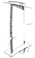
- Fig. 1 is a perspective view illustrating a composite airfoil with leading edge protection made in accordance with the present invention.
- a composite airfoil 10 in accordance with the present invention, includes a coated mesh 12 adjacent with the exterior portion of leading edge 14, the coated mesh being contoured about the leading edge 14 of the airfoil 10 to protect the leading edge 14 against foreign object damage.
- This invention comprises the method for making the composite airfoil 10 with the coated mesh 12 leading edge 14 protection.
- the method of this invention comprises the steps of applying an erosion-resistant coating to a mesh, conforming the coated mesh to the desired airfoil contour, and then integrally molding the coated mesh to the composite airfoil so as to protect the airfoil from erosion and other foreign object damage while also maintaining the aerodynamic shape of the airfoil.
- the mesh is preferably made of a material, such as stainless-steel, which is strong enough to provide the leading edge with enhanced protection against erosion, yet sufficiently pliant, and ductile, so as to be formable about the airfoil's leading edge, and to which an erosion-resistant coating will adhere.
- a material such as stainless-steel
- wire mesh useful with the present invention is a square, plain weave pattern mesh, although other types of mesh may also be utilized.
- substantially parallel lengthwise wires are relatively perpendicular to substantially parallel crosswise wires.
- the lengthwise wires are typically referred to as warp wires, while the crosswise wires are typically referred to as weft wires.
- the warp wires pass over and then under successive weft wires and continue in an over one, under one pattern.
- a void area is formed by the intersection of two adjacent parallel warp wires with two adjacent parallel weft wires. This void area is useful because during the molding process resin infiltrates from the composite through the mesh voids to provide a strong, durable, mechanical interlock between the composite and the mesh.
- the diameter of both the warp and weft wires should be in the range of about 7.62x10 -5 m (3.0 mils) to 1.27x10 -4 m (5.0 mils), with about 1.14x10 -4 m (4.5 mils) being the preferred wire diameter.
- the above-described plain weave pattern mesh is known to those skilled in the art as a Plain Dutch Weave and may be purchased from a variety of companies, including INA Filtration Corporation of South Carolina.
- the mesh Prior to securing the mesh to the composite airfoil the mesh is formed to the approximate contour of the leading edge and is coated with an erosion-resistant coating. If the coating is sufficiently ductile the mesh may be coated first and then formed to the approximate contour of the leading edge. If the mesh contains more weft wires than warp wires then it is preferred that-the mesh be formed so that its warp wires will lie longitudinally along the airfoil's leading edge when the mesh is integrally molded to the airfoil.
- the mesh is then coated on at least one side, with an erosion-resistant coating, such as electrolytic or electroless nickel, to a thickness of about 2.54x10 -6 m (0.1 mil) to 1.27x10 -4 m (5.0 mils), with the preferred thickness being about 2.54x10 -5 m (1.0 mil) to 5.08x10 -5 m (2.0 mils). Both sides of the mesh may be coated, but the side of the mesh which is placed in contact with the airfoil need not be coated.
- an erosion-resistant coating such as electrolytic or electroless nickel
- erosion-resistant coatings such as titanium nitride and titanium diboride, which can be applied to a thickness of 2.54x10 -6 m (0.1 mil) to 1.27x10 -4 m (5.0 mils) in order to improve the mesh's durability, without adding excess weight or impacting the aerodynamic shape of the airfoil.
- titanium nitride and titanium diboride which can be applied to a thickness of 2.54x10 -6 m (0.1 mil) to 1.27x10 -4 m (5.0 mils) in order to improve the mesh's durability, without adding excess weight or impacting the aerodynamic shape of the airfoil.
- the mesh After the mesh is coated it is placed around the lay-up of a composite material which is pre-impregnated with resin, and is formed and secured to the finished airfoil contour by compression molding. During compression molding resin infiltrates from the composite lay-up through the void areas of the mesh and provides a strong, durable interlock between the composite and the wire mesh. This eliminates the need for adhesive bonding which often involves stringent surface preparation and priming procedures of the mesh and/or airfoil.
Description
Claims (5)
- A method of making an erosion-resistant airfoil comprising thc steps of impregnating the airfoil with resin, applying an erosion-resistant coating to a mesh prior to applying the mesh to the airfoil, thereby producing a coated mesh, the mesh having an open construction at its interstices after the erosion-resistant coating is applied, forming said coated mesh to contour about a leading edge of the airfoil, and integrally molding the mesh into the airfoil whereby the resin infiltrates from the airfoil through the mesh to secure the mesh to the airfoil.
- The method of claim 1, wherein said erosion-resistant coating is electroless nickel.
- The method of claim 1, wherein said erosion-resistant coating is electrolytic nickel.
- The method of claim 3, wherein said electrolytic nickel is about 2.54x10⁻⁶m (0.1 mil) to 1.27x10⁻⁴m (5.0 mils) thick.
- A composite airfoil (10) which is resistant to foreign object damage comprising: a metallic mesh (12) molded about its leading edge (14), said metallic mesh having an erosion-resistant coating thereon, such that the mesh has an open construction at its interstices after the erosion-resistant coating is applied to the mesh prior to molding.
Applications Claiming Priority (3)
| Application Number | Priority Date | Filing Date | Title |
|---|---|---|---|
| US08/171,307 US5449273A (en) | 1994-03-21 | 1994-03-21 | Composite airfoil leading edge protection |
| US171307 | 1994-03-21 | ||
| PCT/US1994/014150 WO1995025877A1 (en) | 1994-03-21 | 1994-12-07 | Composite airfoil leading edge protection |
Publications (2)
| Publication Number | Publication Date |
|---|---|
| EP0753098A1 EP0753098A1 (en) | 1997-01-15 |
| EP0753098B1 true EP0753098B1 (en) | 1998-03-18 |
Family
ID=22623274
Family Applications (1)
| Application Number | Title | Priority Date | Filing Date |
|---|---|---|---|
| EP95904855A Expired - Lifetime EP0753098B1 (en) | 1994-03-21 | 1994-12-07 | Composite airfoil leading edge protection |
Country Status (5)
| Country | Link |
|---|---|
| US (1) | US5449273A (en) |
| EP (1) | EP0753098B1 (en) |
| JP (1) | JP3459068B2 (en) |
| DE (1) | DE69409132T2 (en) |
| WO (1) | WO1995025877A1 (en) |
Cited By (1)
| Publication number | Priority date | Publication date | Assignee | Title |
|---|---|---|---|---|
| US11946391B2 (en) | 2021-03-11 | 2024-04-02 | General Electric Company | Turbine engine with composite airfoil having a non-metallic leading edge protective wrap |
Families Citing this family (57)
| Publication number | Priority date | Publication date | Assignee | Title |
|---|---|---|---|---|
| US5876651A (en) * | 1996-05-29 | 1999-03-02 | United Technologies Corporation | Method for forming a composite structure |
| DE19642983C2 (en) * | 1996-10-18 | 2003-06-12 | Mtu Aero Engines Gmbh | Laminate and method for producing a laminate |
| SE508860C2 (en) * | 1997-03-18 | 1998-11-09 | Abb Stal Ab | Device on a guide rail arranged in a rotor machine and a rotatable turbine rail |
| US5938406A (en) * | 1997-04-18 | 1999-08-17 | Varian, Inc. | Rotor for turbomolecular pump |
| US6341747B1 (en) | 1999-10-28 | 2002-01-29 | United Technologies Corporation | Nanocomposite layered airfoil |
| US6607358B2 (en) * | 2002-01-08 | 2003-08-19 | General Electric Company | Multi-component hybrid turbine blade |
| US7736745B2 (en) * | 2004-05-24 | 2010-06-15 | Hontek Corporation | Abrasion resistant coatings |
| US7186092B2 (en) * | 2004-07-26 | 2007-03-06 | General Electric Company | Airfoil having improved impact and erosion resistance and method for preparing same |
| SE528006C2 (en) | 2004-12-23 | 2006-08-01 | Volvo Aero Corp | Static gas turbine component and method of repairing such component |
| DK2502679T3 (en) | 2005-12-14 | 2018-02-26 | Hontek Corp | Method of protecting and repairing a blade surface |
| US20080159870A1 (en) * | 2006-12-14 | 2008-07-03 | Hontek Corporation | Method and coating for protecting and repairing an airfoil surface using molded boots, sheet or tape |
| US7435056B2 (en) | 2006-02-28 | 2008-10-14 | Honeywell International Inc. | Leading edge erosion protection for composite stator vanes |
| US7780420B1 (en) | 2006-11-16 | 2010-08-24 | Florida Turbine Technologies, Inc. | Turbine blade with a foam metal leading or trailing edge |
| ES2329324B1 (en) * | 2007-03-30 | 2010-09-06 | Airbus España, S.L. | REINFORCED COMPOSITE MATERIAL AIRCRAFT ATTACK EDGE. |
| US7736130B2 (en) * | 2007-07-23 | 2010-06-15 | General Electric Company | Airfoil and method for protecting airfoil leading edge |
| US8231958B2 (en) * | 2007-10-09 | 2012-07-31 | United Technologies Corporation | Article and method for erosion resistant composite |
| US20100028160A1 (en) * | 2008-07-31 | 2010-02-04 | General Electric Company | Compressor blade leading edge shim and related method |
| US8956105B2 (en) * | 2008-12-31 | 2015-02-17 | Rolls-Royce North American Technologies, Inc. | Turbine vane for gas turbine engine |
| US20100242843A1 (en) | 2009-03-24 | 2010-09-30 | Peretti Michael W | High temperature additive manufacturing systems for making near net shape airfoils leading edge protection, and tooling systems therewith |
| US8240046B2 (en) * | 2009-03-24 | 2012-08-14 | General Electric Company | Methods for making near net shape airfoil leading edge protection |
| US20110097213A1 (en) * | 2009-03-24 | 2011-04-28 | Peretti Michael W | Composite airfoils having leading edge protection made using high temperature additive manufacturing methods |
| IT1394295B1 (en) | 2009-05-08 | 2012-06-06 | Nuovo Pignone Spa | CENTRIFUGAL IMPELLER OF THE CLOSED TYPE FOR TURBOMACCHINE, COMPONENT FOR SUCH A IMPELLER, TURBOMACCHINA PROVIDED WITH THAT IMPELLER AND METHOD OF REALIZING SUCH A IMPELLER |
| US8419374B2 (en) * | 2009-08-14 | 2013-04-16 | Hamilton Sundstrand Corporation | Gas turbine engine composite blade |
| GB0915087D0 (en) * | 2009-09-01 | 2009-09-30 | Rolls Royce Plc | Aerofoil with erosion resistant leading edge |
| US20110116906A1 (en) * | 2009-11-17 | 2011-05-19 | Smith Blair A | Airfoil component wear indicator |
| IT1397058B1 (en) * | 2009-11-23 | 2012-12-28 | Nuovo Pignone Spa | CENTRIFUGAL IMPELLER MOLD, MOLD INSERTS AND METHOD TO BUILD A CENTRIFUGAL IMPELLER |
| IT1397057B1 (en) | 2009-11-23 | 2012-12-28 | Nuovo Pignone Spa | CENTRIFUGAL AND TURBOMACHINE IMPELLER |
| US8376712B2 (en) * | 2010-01-26 | 2013-02-19 | United Technologies Corporation | Fan airfoil sheath |
| GB201011228D0 (en) * | 2010-07-05 | 2010-08-18 | Rolls Royce Plc | A composite turbomachine blade |
| US9429029B2 (en) | 2010-09-30 | 2016-08-30 | Pratt & Whitney Canada Corp. | Gas turbine blade and method of protecting same |
| US20120082553A1 (en) * | 2010-09-30 | 2012-04-05 | Andreas Eleftheriou | Metal encapsulated stator vane |
| US20120082556A1 (en) * | 2010-09-30 | 2012-04-05 | Enzo Macchia | Nanocrystalline metal coated composite airfoil |
| US9587645B2 (en) | 2010-09-30 | 2017-03-07 | Pratt & Whitney Canada Corp. | Airfoil blade |
| GB201105712D0 (en) | 2011-04-05 | 2011-05-18 | Rolls Royce Plc | A component having an erosion-resistant layer |
| US8642164B2 (en) | 2011-09-15 | 2014-02-04 | United Technologies Corporation | Composite substrates with predetermined porosities |
| ITCO20110064A1 (en) | 2011-12-14 | 2013-06-15 | Nuovo Pignone Spa | ROTARY MACHINE INCLUDING A ROTOR WITH A COMPOSITE IMPELLER AND A METAL SHAFT |
| US20130199934A1 (en) | 2012-02-06 | 2013-08-08 | United Technologies Corporation | Electroformed sheath |
| US9427835B2 (en) | 2012-02-29 | 2016-08-30 | Pratt & Whitney Canada Corp. | Nano-metal coated vane component for gas turbine engines and method of manufacturing same |
| US9410438B2 (en) * | 2013-03-08 | 2016-08-09 | Pratt & Whitney Canada Corp. | Dual rotor blades having a metal leading airfoil and a trailing airfoil of a composite material for gas turbine engines |
| US20140271214A1 (en) * | 2013-03-14 | 2014-09-18 | Bell Helicopter Textron Inc. | Amorphous metal rotor blade abrasion strip |
| ITCO20130067A1 (en) | 2013-12-17 | 2015-06-18 | Nuovo Pignone Srl | IMPELLER WITH PROTECTION ELEMENTS AND CENTRIFUGAL COMPRESSOR |
| FR3049001B1 (en) | 2016-03-21 | 2019-07-12 | Safran Aircraft Engines | A CARRIED PROPELLER AERONAUTICAL TURBOMACHINE HAVING BLADES HAVING AN ELEMENT REPORTED IN COMPOSITE MATERIAL GLUE ON THEIR EDGE EDGE |
| GB2549113A (en) * | 2016-04-05 | 2017-10-11 | Rolls Royce Plc | Composite bodies and their manufacture |
| US10677259B2 (en) | 2016-05-06 | 2020-06-09 | General Electric Company | Apparatus and system for composite fan blade with fused metal lead edge |
| US10612386B2 (en) | 2017-07-17 | 2020-04-07 | Rolls-Royce Corporation | Apparatus for airfoil leading edge protection |
| US11408291B2 (en) | 2018-07-27 | 2022-08-09 | Raytheon Technologies Corporation | Airfoil conformable membrane erosion coating |
| US11434781B2 (en) | 2018-10-16 | 2022-09-06 | General Electric Company | Frangible gas turbine engine airfoil including an internal cavity |
| US11149558B2 (en) | 2018-10-16 | 2021-10-19 | General Electric Company | Frangible gas turbine engine airfoil with layup change |
| US10837286B2 (en) | 2018-10-16 | 2020-11-17 | General Electric Company | Frangible gas turbine engine airfoil with chord reduction |
| US10746045B2 (en) | 2018-10-16 | 2020-08-18 | General Electric Company | Frangible gas turbine engine airfoil including a retaining member |
| US11111815B2 (en) | 2018-10-16 | 2021-09-07 | General Electric Company | Frangible gas turbine engine airfoil with fusion cavities |
| US10760428B2 (en) | 2018-10-16 | 2020-09-01 | General Electric Company | Frangible gas turbine engine airfoil |
| FR3090465B1 (en) * | 2018-12-20 | 2021-03-19 | Safran | METHOD OF MANUFACTURING A TURBOMACHINE PART IN COMPOSITE MATERIAL AND CORRESPONDING TURBOMACHINE PART |
| US11725524B2 (en) | 2021-03-26 | 2023-08-15 | General Electric Company | Engine airfoil metal edge |
| US11674399B2 (en) | 2021-07-07 | 2023-06-13 | General Electric Company | Airfoil arrangement for a gas turbine engine utilizing a shape memory alloy |
| US11668317B2 (en) | 2021-07-09 | 2023-06-06 | General Electric Company | Airfoil arrangement for a gas turbine engine utilizing a shape memory alloy |
| US11767607B1 (en) | 2022-07-13 | 2023-09-26 | General Electric Company | Method of depositing a metal layer on a component |
Family Cites Families (36)
| Publication number | Priority date | Publication date | Assignee | Title |
|---|---|---|---|---|
| US1367132A (en) * | 1919-02-15 | 1921-02-01 | Westinghouse Electric & Mfg Co | Variable-pitch propeller |
| US1674674A (en) * | 1926-08-06 | 1928-06-26 | Stanton H Wooster | Propeller |
| US1860557A (en) * | 1930-09-12 | 1932-05-31 | Firm Gustav Schwarz G M B H | Propeller for aircraft |
| US2161533A (en) * | 1936-02-01 | 1939-06-06 | Hugo Heine | Means for protecting wooden propellers |
| US2477375A (en) * | 1944-03-22 | 1949-07-26 | Jablonsky Bruno | Method of manufacturing hollow articles of bonded fibrous laminae |
| US2644296A (en) * | 1948-01-15 | 1953-07-07 | North American Aviation Inc | Laminated jet vane |
| US2767461A (en) * | 1951-03-27 | 1956-10-23 | Lockheed Aircraft Corp | Method of making propeller or rotor blade |
| US2994124A (en) * | 1955-10-03 | 1961-08-01 | Gen Electric | Clad cermet body |
| US3041040A (en) * | 1955-12-23 | 1962-06-26 | Gen Electric | Metal clad blade |
| US2897583A (en) * | 1956-10-15 | 1959-08-04 | Networks Electronic Corp | Method of fusing metal to glass articles |
| GB1040825A (en) * | 1965-04-20 | 1966-09-01 | Rolls Royce | Improvements in rotor blades and/or stator blades for gas turbine engines |
| GB1250885A (en) * | 1967-12-05 | 1971-10-20 | ||
| GB1268202A (en) * | 1968-08-01 | 1972-03-22 | Rolls Royce | Composite blade for an elastic fluid flow machine |
| GB1186486A (en) * | 1968-10-22 | 1970-04-02 | Rolls Royce | Fibre Reinforced Blade |
| GB1284538A (en) * | 1968-11-19 | 1972-08-09 | Rolls Royce | Blade for a fluid flow machine |
| US3572971A (en) * | 1969-09-29 | 1971-03-30 | Gen Electric | Lightweight turbo-machinery blading |
| US3600103A (en) * | 1969-10-06 | 1971-08-17 | United Aircraft Corp | Composite blade |
| US3649865A (en) * | 1969-12-29 | 1972-03-14 | Tektronix Inc | Wire mesh member having intersecting strands bonded together and method of manufacture |
| CA928637A (en) * | 1970-09-15 | 1973-06-19 | General Electric Company | Compressor blades |
| US3701190A (en) * | 1971-04-07 | 1972-10-31 | United Aircraft Corp | Apparatus for and the method of compacting an irregularly shaped article |
| US3892612A (en) * | 1971-07-02 | 1975-07-01 | Gen Electric | Method for fabricating foreign object damage protection for rotar blades |
| US3762835A (en) * | 1971-07-02 | 1973-10-02 | Gen Electric | Foreign object damage protection for compressor blades and other structures and related methods |
| BE789793A (en) * | 1971-10-06 | 1973-04-06 | Hoesch Ag | PROCESS FOR PRE-TREATMENT OF STEEL STRIPS AND SHEETS WITH A VIEW TO A SINGLE-LAYER ENAMEL |
| FR2195255A5 (en) * | 1972-08-04 | 1974-03-01 | Snecma | |
| US4006999A (en) * | 1975-07-17 | 1977-02-08 | The United States Of America As Represented By The Administrator Of The National Aeronautics And Space Administration | Leading edge protection for composite blades |
| US4000956A (en) * | 1975-12-22 | 1977-01-04 | General Electric Company | Impact resistant blade |
| US4111606A (en) * | 1976-12-27 | 1978-09-05 | United Technologies Corporation | Composite rotor blade |
| DE3151413A1 (en) * | 1981-12-24 | 1983-07-14 | MTU Motoren- und Turbinen-Union München GmbH, 8000 München | "SHOVEL OF A FLUID MACHINE, IN PARTICULAR GAS TURBINE" |
| JPS59123786A (en) * | 1982-12-29 | 1984-07-17 | Toshiba Corp | Tungsten wire |
| DE3317628A1 (en) * | 1983-05-14 | 1984-11-15 | Kalkspatgruben und Labranit-Edelputzwerk Heinrich Lahme, 5790 Brilon | Thermal insulating board with plaster lath |
| FR2599425B1 (en) * | 1986-05-28 | 1988-08-05 | Alsthom | PROTECTIVE PLATE FOR TITANIUM BLADE AND METHOD OF BRAZING SUCH A PLATE. |
| DE3815906A1 (en) * | 1988-05-10 | 1989-11-23 | Mtu Muenchen Gmbh | PROPELLER BLADE MADE OF FIBER REINFORCED PLASTIC |
| US5174024A (en) * | 1990-09-17 | 1992-12-29 | Sterrett Terry L | Tail rotor abrasive strip |
| US5210944A (en) * | 1990-11-13 | 1993-05-18 | General Electric Company | Method for making a gas turbine engine component |
| US5141400A (en) * | 1991-01-25 | 1992-08-25 | General Electric Company | Wide chord fan blade |
| US5296183A (en) * | 1992-08-21 | 1994-03-22 | Dow-United Technologies Composite Products, Inc. | Method for comolding property enhancing coatings to composite articles |
-
1994
- 1994-03-21 US US08/171,307 patent/US5449273A/en not_active Expired - Lifetime
- 1994-12-07 WO PCT/US1994/014150 patent/WO1995025877A1/en active IP Right Grant
- 1994-12-07 JP JP52462395A patent/JP3459068B2/en not_active Expired - Fee Related
- 1994-12-07 DE DE69409132T patent/DE69409132T2/en not_active Expired - Lifetime
- 1994-12-07 EP EP95904855A patent/EP0753098B1/en not_active Expired - Lifetime
Cited By (1)
| Publication number | Priority date | Publication date | Assignee | Title |
|---|---|---|---|---|
| US11946391B2 (en) | 2021-03-11 | 2024-04-02 | General Electric Company | Turbine engine with composite airfoil having a non-metallic leading edge protective wrap |
Also Published As
| Publication number | Publication date |
|---|---|
| DE69409132D1 (en) | 1998-04-23 |
| EP0753098A1 (en) | 1997-01-15 |
| WO1995025877A1 (en) | 1995-09-28 |
| DE69409132T2 (en) | 1998-11-19 |
| JPH09510529A (en) | 1997-10-21 |
| US5449273A (en) | 1995-09-12 |
| JP3459068B2 (en) | 2003-10-20 |
Similar Documents
| Publication | Publication Date | Title |
|---|---|---|
| EP0753098B1 (en) | Composite airfoil leading edge protection | |
| US3762835A (en) | Foreign object damage protection for compressor blades and other structures and related methods | |
| US3892612A (en) | Method for fabricating foreign object damage protection for rotar blades | |
| US10364823B2 (en) | Airfoil blade | |
| US5951254A (en) | Blade for fluid flow engine having a metallic coating layer, and method of manufacturing and repairing the same | |
| US7575417B2 (en) | Reinforced fan blade | |
| JP3924333B2 (en) | Composite blade | |
| EP0769094B1 (en) | Erosion resistant surface protection | |
| US4006999A (en) | Leading edge protection for composite blades | |
| US5887332A (en) | Hybrid component with high strength/mass ratio and method of manufacturing said component | |
| CA2754240A1 (en) | Gas turbine engine casing | |
| CA2754254A1 (en) | Nanocrystalline metal coated composite airfoil | |
| JP2019518161A (en) | Wind turbine blade leading edge protection | |
| EP2508712A2 (en) | A component having an erosion-resistant layer | |
| CN109878124B (en) | Blade and method for manufacturing the same | |
| US5132168A (en) | Lightning strike protection for composite aircraft structures | |
| CN115768966A (en) | Turbine blade with metal leading edge | |
| CN114901921A (en) | Composite blade with additional variable density leading edge | |
| US10718350B2 (en) | Fan blade with galvanic separator | |
| WO1996001288A2 (en) | Method for improving the erosion resistance of engine components | |
| CN112189079B (en) | Fabric comprising aramid fibers for protecting blades from impacts | |
| Brantley et al. | Leading edge protection for composite blades |
Legal Events
| Date | Code | Title | Description |
|---|---|---|---|
| PUAI | Public reference made under article 153(3) epc to a published international application that has entered the european phase |
Free format text: ORIGINAL CODE: 0009012 |
|
| 17P | Request for examination filed |
Effective date: 19961015 |
|
| AK | Designated contracting states |
Kind code of ref document: A1 Designated state(s): DE FR GB |
|
| GRAG | Despatch of communication of intention to grant |
Free format text: ORIGINAL CODE: EPIDOS AGRA |
|
| 17Q | First examination report despatched |
Effective date: 19970206 |
|
| GRAG | Despatch of communication of intention to grant |
Free format text: ORIGINAL CODE: EPIDOS AGRA |
|
| GRAH | Despatch of communication of intention to grant a patent |
Free format text: ORIGINAL CODE: EPIDOS IGRA |
|
| GRAH | Despatch of communication of intention to grant a patent |
Free format text: ORIGINAL CODE: EPIDOS IGRA |
|
| GRAA | (expected) grant |
Free format text: ORIGINAL CODE: 0009210 |
|
| AK | Designated contracting states |
Kind code of ref document: B1 Designated state(s): DE FR GB |
|
| ET | Fr: translation filed | ||
| REF | Corresponds to: |
Ref document number: 69409132 Country of ref document: DE Date of ref document: 19980423 |
|
| PLBE | No opposition filed within time limit |
Free format text: ORIGINAL CODE: 0009261 |
|
| STAA | Information on the status of an ep patent application or granted ep patent |
Free format text: STATUS: NO OPPOSITION FILED WITHIN TIME LIMIT |
|
| 26N | No opposition filed | ||
| REG | Reference to a national code |
Ref country code: GB Ref legal event code: IF02 |
|
| PGFP | Annual fee paid to national office [announced via postgrant information from national office to epo] |
Ref country code: FR Payment date: 20081205 Year of fee payment: 15 |
|
| REG | Reference to a national code |
Ref country code: FR Ref legal event code: ST Effective date: 20100831 |
|
| PG25 | Lapsed in a contracting state [announced via postgrant information from national office to epo] |
Ref country code: FR Free format text: LAPSE BECAUSE OF NON-PAYMENT OF DUE FEES Effective date: 20091231 |
|
| PGFP | Annual fee paid to national office [announced via postgrant information from national office to epo] |
Ref country code: DE Payment date: 20121205 Year of fee payment: 19 |
|
| PGFP | Annual fee paid to national office [announced via postgrant information from national office to epo] |
Ref country code: GB Payment date: 20121205 Year of fee payment: 19 |
|
| REG | Reference to a national code |
Ref country code: DE Ref legal event code: R119 Ref document number: 69409132 Country of ref document: DE |
|
| GBPC | Gb: european patent ceased through non-payment of renewal fee |
Effective date: 20131207 |
|
| REG | Reference to a national code |
Ref country code: DE Ref legal event code: R119 Ref document number: 69409132 Country of ref document: DE Effective date: 20140701 |
|
| PG25 | Lapsed in a contracting state [announced via postgrant information from national office to epo] |
Ref country code: DE Free format text: LAPSE BECAUSE OF NON-PAYMENT OF DUE FEES Effective date: 20140701 |
|
| PG25 | Lapsed in a contracting state [announced via postgrant information from national office to epo] |
Ref country code: GB Free format text: LAPSE BECAUSE OF NON-PAYMENT OF DUE FEES Effective date: 20131207 |