EP0752940B1 - Elektrohydraulische druckeinstellvorrichtung, insbesondere für eine schlupfgeregelte fahrzeugbremsanlage - Google Patents
Elektrohydraulische druckeinstellvorrichtung, insbesondere für eine schlupfgeregelte fahrzeugbremsanlage Download PDFInfo
- Publication number
- EP0752940B1 EP0752940B1 EP95913055A EP95913055A EP0752940B1 EP 0752940 B1 EP0752940 B1 EP 0752940B1 EP 95913055 A EP95913055 A EP 95913055A EP 95913055 A EP95913055 A EP 95913055A EP 0752940 B1 EP0752940 B1 EP 0752940B1
- Authority
- EP
- European Patent Office
- Prior art keywords
- valve block
- coil
- valve
- cover
- spring
- Prior art date
- Legal status (The legal status is an assumption and is not a legal conclusion. Google has not performed a legal analysis and makes no representation as to the accuracy of the status listed.)
- Expired - Lifetime
Links
- 230000001105 regulatory effect Effects 0.000 title 1
- 210000002105 tongue Anatomy 0.000 claims description 11
- 238000000034 method Methods 0.000 description 4
- 238000011161 development Methods 0.000 description 3
- 230000018109 developmental process Effects 0.000 description 3
- 238000004519 manufacturing process Methods 0.000 description 2
- 238000004804 winding Methods 0.000 description 2
- 239000000969 carrier Substances 0.000 description 1
- 230000006835 compression Effects 0.000 description 1
- 238000007906 compression Methods 0.000 description 1
- 238000006073 displacement reaction Methods 0.000 description 1
- 230000036316 preload Effects 0.000 description 1
Images
Classifications
-
- B—PERFORMING OPERATIONS; TRANSPORTING
- B60—VEHICLES IN GENERAL
- B60T—VEHICLE BRAKE CONTROL SYSTEMS OR PARTS THEREOF; BRAKE CONTROL SYSTEMS OR PARTS THEREOF, IN GENERAL; ARRANGEMENT OF BRAKING ELEMENTS ON VEHICLES IN GENERAL; PORTABLE DEVICES FOR PREVENTING UNWANTED MOVEMENT OF VEHICLES; VEHICLE MODIFICATIONS TO FACILITATE COOLING OF BRAKES
- B60T8/00—Arrangements for adjusting wheel-braking force to meet varying vehicular or ground-surface conditions, e.g. limiting or varying distribution of braking force
- B60T8/32—Arrangements for adjusting wheel-braking force to meet varying vehicular or ground-surface conditions, e.g. limiting or varying distribution of braking force responsive to a speed condition, e.g. acceleration or deceleration
- B60T8/34—Arrangements for adjusting wheel-braking force to meet varying vehicular or ground-surface conditions, e.g. limiting or varying distribution of braking force responsive to a speed condition, e.g. acceleration or deceleration having a fluid pressure regulator responsive to a speed condition
- B60T8/36—Arrangements for adjusting wheel-braking force to meet varying vehicular or ground-surface conditions, e.g. limiting or varying distribution of braking force responsive to a speed condition, e.g. acceleration or deceleration having a fluid pressure regulator responsive to a speed condition including a pilot valve responding to an electromagnetic force
-
- B—PERFORMING OPERATIONS; TRANSPORTING
- B60—VEHICLES IN GENERAL
- B60T—VEHICLE BRAKE CONTROL SYSTEMS OR PARTS THEREOF; BRAKE CONTROL SYSTEMS OR PARTS THEREOF, IN GENERAL; ARRANGEMENT OF BRAKING ELEMENTS ON VEHICLES IN GENERAL; PORTABLE DEVICES FOR PREVENTING UNWANTED MOVEMENT OF VEHICLES; VEHICLE MODIFICATIONS TO FACILITATE COOLING OF BRAKES
- B60T8/00—Arrangements for adjusting wheel-braking force to meet varying vehicular or ground-surface conditions, e.g. limiting or varying distribution of braking force
- B60T8/32—Arrangements for adjusting wheel-braking force to meet varying vehicular or ground-surface conditions, e.g. limiting or varying distribution of braking force responsive to a speed condition, e.g. acceleration or deceleration
- B60T8/34—Arrangements for adjusting wheel-braking force to meet varying vehicular or ground-surface conditions, e.g. limiting or varying distribution of braking force responsive to a speed condition, e.g. acceleration or deceleration having a fluid pressure regulator responsive to a speed condition
- B60T8/36—Arrangements for adjusting wheel-braking force to meet varying vehicular or ground-surface conditions, e.g. limiting or varying distribution of braking force responsive to a speed condition, e.g. acceleration or deceleration having a fluid pressure regulator responsive to a speed condition including a pilot valve responding to an electromagnetic force
- B60T8/3615—Electromagnetic valves specially adapted for anti-lock brake and traction control systems
- B60T8/3675—Electromagnetic valves specially adapted for anti-lock brake and traction control systems integrated in modulator units
Definitions
- the invention is based on an electrohydraulic pressure setting device according to the genus of the claim.
- Such an electro-hydraulic is already from DE 41 00 967 A1 Pressure setting device known in the case of a hood-shaped Cover the coils of solenoid valves elastic are resiliently hung around when joining with a valve block relative to this, d. H. radially and axially adjustable to be.
- elastic brackets in the form of Helical compression springs are provided between the cover and the coils, by a force directed against the valve block to produce the coils. After joining should be defined by a axial pressure of the coils against the valve block the location of which are secured.
- the coils in the cover are on a stop to absorb the force of the springs, thus contact elements that connect the coils with a the electronic regulator in the lid is located above this connect, not be overused.
- the constructive The effort to absorb the spring forces in the cover is relative high.
- the embodiment of the invention according to claim 2 has the advantage of spring force-free introduction of the spring force into the coil.
- the measure according to claim 4 has the advantage that the spring plate are captively preassembled and arranged on the lid also a transport protection for the coil in the lid can form.
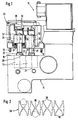
- FIG. 1 shows a view of a Pressure adjustment device while fitting in a lid recorded coils on a valve block
- Figure 2 is a view seen in the direction of arrow II in Figure 1 on a between the Coils and the valve block arranged spring element.
- FIG. 1 10 An electro-hydraulic pressure adjustment device shown in Figure 1 10 for a slip-controlled vehicle brake system consists essentially of a valve block 11, in the valves 12 are received, and from a hood-shaped Cover 13 with electrical elements arranged therein such as coils 14 for the electromagnetic actuation of the valves 12.
- Figure 1 shows a state when joining the lid 13 on the valve block 11 again. In fully assembled condition is the lid 13 along a support surface 15 of the Valve blocks 11 combined with this and by screws 16 connected.
- the valves 12 are arranged in the valve block 11 in two rows, which are parallel to each other perpendicular extend to the drawing plane. In the same way they are in the essentially from winding, winding carriers, connecting wires and magnetic flux-conducting jacket existing coils 14 within of the lid 13 arranged.
- the coils 14 are through compliant electrical contact elements 19 with an im Cover 13 arranged electronic controller 20 connected. Due to the flexibility of the contact elements 19 can the coils 14 in axial and with respect to their longitudinal axis 21 radial direction subjected to changes in their position in the lid 13 will.
- the valves 12 each have one over the support surface 15 of the valve block 11 upstanding valve dome 22.
- the diameter of the circular cylindrical valve dome 22 is matched to the inner bore 25 of the coils 14.
- the valve block 11 a spring element in the form of a spring plate 28 is arranged.
- the spring plate shown in Figure 2 in plan view 28 has a web running continuously in the longitudinal direction 29, of the spring tongues extending at right angles to this 30 go out on both sides. Two adjacent spring tongues each 30 are assigned to a coil 14.
- the web 29 is on the support surface 15 supported, while the spring tongues 30th take a distance from the support surface with its free end.
- the spring tongue pairs mentioned each close a valve dome 22 between them, as shown in FIG.
- the spring plate 28 inserted between the valve block 11 and the cover 13. Deviating of which the spring plate 28 can also be used in the area of the Web 29 lying fasteners, not shown be provided, such as tongues, for example, in a Engage the bore of the valve block 11 and lock it in place are. As a result, the spring plate 28 is captive, so that it already when installing the valve block assembly 11 this can be arranged.
- the fasteners can but also for the assignment of the spring plate 28 to the cover 13 or be formed on at least one coil 14. At a sufficiently intimate connection with the lid 13 can the spring plate 28 also as transport protection for the in the lid 13 mounted coils 14 until the final assembly on Serve valve block 11.
Landscapes
- Physics & Mathematics (AREA)
- Engineering & Computer Science (AREA)
- Electromagnetism (AREA)
- Fluid Mechanics (AREA)
- Transportation (AREA)
- Mechanical Engineering (AREA)
- Magnetically Actuated Valves (AREA)
- Valves And Accessory Devices For Braking Systems (AREA)
- Regulating Braking Force (AREA)
Description
Claims (4)
- Elektrohydraulische Druckeinstellvorrichtung (10), inbesondere für eine schlupfgeregelte Fahrzeugbremsanlage, mit wenigstens einem elektromagnetisch betätigbaren Ventil (12), das mit einem Ventilblock (11) vereinigt ist und einen vom Ventilblock aufragenden Ventildom (22) sowie eine zu dem Ventildom ausrichtbare und auf diesen steckbare Spule (14) hat, mit einem die Spule (14) und den Ventildom (22) bedeckenden, am Ventilblock (11) befestigten Deckel (13) sowie mit einem die aufgesteckte Spule (14) axial haltenden Federelement (28), wobei die Spule des Ventils (12) vor dem Fügen von Deckel und Ventilblock elastisch nachgiebig am Deckel (13) aufgehängt ist, dadurch gekennzeichnet, daß das Federelement ein Federblech (28) ist, welches einerseits am Ventilblock (11) und andererseits an der Spule (14) angreift und daß die Spule ventilblockabgewandt am Deckel (13) axial abgestützt ist.
- Elektrohydraulische Druckeinstellvorrichtung nach Anspruch 1, dadurch gekennzeichnet, daß das Federblech (28) an diametral gegenüberliegenden Zonen der ventilblockzugewandten Stirnseite (31) der Spule (14) angreift.
- Elektrohydraulische Druckeinstellvorrichtung nach Anspruch 1 oder 2, mit in zwei parallelen Reihen gegenüberliegend angeordneten Ventilen (12), dadurch gekennzeichnet, daß das Federblech (28) einen sich zwischen den Reihen erstreckenden, am Ventilblock (11) abgestützten Steg (29) hat, von dem im wesentlichen rechtwinklig zu diesem verlaufende Federzungen (30) zu den Spulen (14) beider Reihen ausgehen.
- Elektrohydraulische Druckeinstellvorrichtung nach Anspruch 1 oder 3, dadurch gekennzeichnet, daß das Federblech (28) unverlierbar am Deckel (13), an wenigstens einer Spule (14) oder am Ventilblock (11) gehalten ist.
Applications Claiming Priority (3)
| Application Number | Priority Date | Filing Date | Title |
|---|---|---|---|
| DE4412665A DE4412665A1 (de) | 1994-04-13 | 1994-04-13 | Elektrohydraulische Druckeinstellvorrichtung, insbesondere für eine schlupfgeregelte Fahrzeugbremsanlage |
| DE4412665 | 1994-04-13 | ||
| PCT/DE1995/000412 WO1995028304A1 (de) | 1994-04-13 | 1995-03-27 | Elektrohydraulische druckeinstellvorrichtung, insbesondere für eine schlupfgeregelte fahrzeugbremsanlage |
Publications (2)
| Publication Number | Publication Date |
|---|---|
| EP0752940A1 EP0752940A1 (de) | 1997-01-15 |
| EP0752940B1 true EP0752940B1 (de) | 1998-12-02 |
Family
ID=6515251
Family Applications (1)
| Application Number | Title | Priority Date | Filing Date |
|---|---|---|---|
| EP95913055A Expired - Lifetime EP0752940B1 (de) | 1994-04-13 | 1995-03-27 | Elektrohydraulische druckeinstellvorrichtung, insbesondere für eine schlupfgeregelte fahrzeugbremsanlage |
Country Status (7)
| Country | Link |
|---|---|
| US (1) | US5779221A (de) |
| EP (1) | EP0752940B1 (de) |
| JP (1) | JPH09511965A (de) |
| KR (1) | KR100346969B1 (de) |
| DE (2) | DE4412665A1 (de) |
| ES (1) | ES2125606T3 (de) |
| WO (1) | WO1995028304A1 (de) |
Families Citing this family (7)
| Publication number | Priority date | Publication date | Assignee | Title |
|---|---|---|---|---|
| DE19503819B4 (de) * | 1995-02-06 | 2005-10-20 | Bosch Gmbh Robert | Hydraulikaggregat für eine schlupfgeregelte Fahrzeugbremsanlage |
| KR100328227B1 (ko) * | 1997-12-30 | 2002-04-17 | 밍 루 | 안티록 브레이크 시스템 |
| US6354674B1 (en) * | 1998-12-11 | 2002-03-12 | Denso Corporation | Hydraulic control apparatus integrated with motor driving circuit unit |
| DE19959021B4 (de) * | 1999-12-08 | 2004-04-08 | Robert Bosch Gmbh | Elektromagnetisch betätigbares Proportionalventil |
| JP3861672B2 (ja) * | 2000-12-13 | 2006-12-20 | 株式会社デンソー | 電磁弁およびその電磁弁を用いた流体制御装置 |
| DE10104875A1 (de) * | 2001-02-03 | 2002-08-08 | Bosch Gmbh Robert | Hydraulikaggregat für schlupfgeregelte Bremsanlagen von Kraftfahrzeugen sowie Verfahren zu dessen Herstellung |
| JP4520915B2 (ja) * | 2005-07-13 | 2010-08-11 | 日信工業株式会社 | 車両用ブレーキ液圧制御装置 |
Family Cites Families (7)
| Publication number | Priority date | Publication date | Assignee | Title |
|---|---|---|---|---|
| GB686658A (en) * | 1951-03-06 | 1953-01-28 | Skinner Chuck Company | Improvements in valve construction |
| GB2074233B (en) * | 1978-02-07 | 1983-02-02 | Bendix Corp | Fuel-handling arrangement in an ic engine fuel-injection system |
| GB2249874B (en) * | 1990-11-17 | 1994-09-21 | Motorola Gmbh | Elastomeric seating member |
| DE4100967A1 (de) * | 1991-01-15 | 1992-07-16 | Teves Gmbh Alfred | Elektrohydraulische druckregelvorrichtung |
| DE4141546C2 (de) * | 1991-12-17 | 2002-02-14 | Continental Teves Ag & Co Ohg | Elektromagnetventil, insbesondere für hydraulische Bremsanlagen mit Schlupfregelung |
| DE4306769A1 (de) * | 1993-03-04 | 1994-09-08 | Bosch Gmbh Robert | Druckregelvorrichtung für eine schlupfgeregelte hydraulische Bremsanlage, insbesondere für Kraftfahrzeuge |
| US5364067A (en) * | 1994-02-18 | 1994-11-15 | Kelsey-Hayes Corporation | Vehicular anti-lock brake system hydraulic control valve and method of making same |
-
1994
- 1994-04-13 DE DE4412665A patent/DE4412665A1/de not_active Withdrawn
-
1995
- 1995-03-27 WO PCT/DE1995/000412 patent/WO1995028304A1/de not_active Ceased
- 1995-03-27 JP JP7526611A patent/JPH09511965A/ja active Pending
- 1995-03-27 KR KR1019960705799A patent/KR100346969B1/ko not_active Expired - Fee Related
- 1995-03-27 ES ES95913055T patent/ES2125606T3/es not_active Expired - Lifetime
- 1995-03-27 US US08/727,383 patent/US5779221A/en not_active Expired - Fee Related
- 1995-03-27 DE DE59504423T patent/DE59504423D1/de not_active Expired - Fee Related
- 1995-03-27 EP EP95913055A patent/EP0752940B1/de not_active Expired - Lifetime
Also Published As
| Publication number | Publication date |
|---|---|
| WO1995028304A1 (de) | 1995-10-26 |
| ES2125606T3 (es) | 1999-03-01 |
| EP0752940A1 (de) | 1997-01-15 |
| KR100346969B1 (ko) | 2002-11-04 |
| US5779221A (en) | 1998-07-14 |
| DE59504423D1 (de) | 1999-01-14 |
| DE4412665A1 (de) | 1995-10-19 |
| JPH09511965A (ja) | 1997-12-02 |
| KR970702184A (ko) | 1997-05-13 |
Similar Documents
| Publication | Publication Date | Title |
|---|---|---|
| EP0783420B1 (de) | Elektrohydraulische druckeinstellvorrichtung, insbesondere für eine schlupfgeregelte fahrzeugbremsanlage | |
| EP0752941B1 (de) | Elektrohydraulische druckeinstellvorrichtung, insbesondere für eine schlupfgeregelte fahrzeugbremsanlage | |
| DE69517335T2 (de) | Elektromagnetisch gelenktes ventil mit gelenkter armatur | |
| DE19644963B4 (de) | Druckregelgerät | |
| EP0951412A1 (de) | Magnetventil | |
| EP1503926A1 (de) | Elektromagnetventil | |
| DE102008040180A1 (de) | Vormontagebaugruppe für eine Kontaktanordnung einer Sensorbaugruppe | |
| DE10036086A1 (de) | Elektrische Verbindung von Aktuatoren oder Sensoren mit Kontakten eines Schaltungsträgers und Bremsdruckregelvorrichtung oder aktives Feder-oder Dämpfungssystem sowie Gehäuse für die Bremsdruckregelvorrichtung oder das aktive Feder -oder Dämpfungssystem | |
| DE102010062262A1 (de) | Aktuator für eine verstellbare Dämpfventileinrichtung | |
| DE10245797B4 (de) | Vorrichtung zur schwingungsdämpfenden Anordnung eines Aggregats und mit derartigen Vorrichtungen ausgestattetes Aggregat | |
| DE4412665A1 (de) | Elektrohydraulische Druckeinstellvorrichtung, insbesondere für eine schlupfgeregelte Fahrzeugbremsanlage | |
| EP1165354A1 (de) | Anordnung zur kontaktierung eines elektrischen bauteils mit einer elektrischen schaltung | |
| EP1360097B1 (de) | Hydraulikaggregat fur schlupfgeregelte kraftfahrzeugbremsanlagen sowie sein herstellungsverfahren | |
| DE19745775C2 (de) | Zentriereinrichtung an einem Bremssattel | |
| DE102008024101A1 (de) | Ventilanordnung, insbesondere für schlupfgeregelte Kraftfahrzeug-Bremsanlagen | |
| DE19848845A1 (de) | Stößeleinrichtung für eine Brennstoffeinspritzvorrichtung | |
| DE102019000444A1 (de) | Bremsbelaganordnung für eine Fahrzeugscheibenbremse | |
| DE60127230T2 (de) | Ventildeaktivierungseinrichtung | |
| DE112020004411T5 (de) | Injektorbefestigungsstruktur | |
| WO2003018969A1 (de) | Lösbare verbindung zum kuppeln eines gaswechselventils einer brennkraftmaschine mit einem aktor | |
| DE4442634A1 (de) | Vorrichtung zum Befestigen eines Einzelspulenzündsystems mit dem Zylinderkopf einer Brennkraftmaschine | |
| DE10347759A1 (de) | Struktur und Verfahren zum Koppeln eines Wellenelements und eines zylindrischen Elements | |
| DE19718835A1 (de) | Elektrohydraulisches Druckregelgerät | |
| DE102007019800A1 (de) | Anordnung mit Magnetspule und Verfahren zur Herstellung | |
| DE19919396A1 (de) | Spulenträgerlose Elektromagnetspule |
Legal Events
| Date | Code | Title | Description |
|---|---|---|---|
| PUAI | Public reference made under article 153(3) epc to a published international application that has entered the european phase |
Free format text: ORIGINAL CODE: 0009012 |
|
| 17P | Request for examination filed |
Effective date: 19961113 |
|
| AK | Designated contracting states |
Kind code of ref document: A1 Designated state(s): DE ES GB IT |
|
| GRAG | Despatch of communication of intention to grant |
Free format text: ORIGINAL CODE: EPIDOS AGRA |
|
| 17Q | First examination report despatched |
Effective date: 19980317 |
|
| GRAG | Despatch of communication of intention to grant |
Free format text: ORIGINAL CODE: EPIDOS AGRA |
|
| GRAH | Despatch of communication of intention to grant a patent |
Free format text: ORIGINAL CODE: EPIDOS IGRA |
|
| GRAH | Despatch of communication of intention to grant a patent |
Free format text: ORIGINAL CODE: EPIDOS IGRA |
|
| GRAA | (expected) grant |
Free format text: ORIGINAL CODE: 0009210 |
|
| AK | Designated contracting states |
Kind code of ref document: B1 Designated state(s): DE ES GB IT |
|
| REF | Corresponds to: |
Ref document number: 59504423 Country of ref document: DE Date of ref document: 19990114 |
|
| ITF | It: translation for a ep patent filed | ||
| GBT | Gb: translation of ep patent filed (gb section 77(6)(a)/1977) |
Effective date: 19990203 |
|
| REG | Reference to a national code |
Ref country code: ES Ref legal event code: FG2A Ref document number: 2125606 Country of ref document: ES Kind code of ref document: T3 |
|
| PLBE | No opposition filed within time limit |
Free format text: ORIGINAL CODE: 0009261 |
|
| STAA | Information on the status of an ep patent application or granted ep patent |
Free format text: STATUS: NO OPPOSITION FILED WITHIN TIME LIMIT |
|
| 26N | No opposition filed | ||
| REG | Reference to a national code |
Ref country code: GB Ref legal event code: IF02 |
|
| PGFP | Annual fee paid to national office [announced via postgrant information from national office to epo] |
Ref country code: GB Payment date: 20030227 Year of fee payment: 9 |
|
| PGFP | Annual fee paid to national office [announced via postgrant information from national office to epo] |
Ref country code: ES Payment date: 20030311 Year of fee payment: 9 |
|
| PGFP | Annual fee paid to national office [announced via postgrant information from national office to epo] |
Ref country code: DE Payment date: 20030425 Year of fee payment: 9 |
|
| PG25 | Lapsed in a contracting state [announced via postgrant information from national office to epo] |
Ref country code: GB Free format text: LAPSE BECAUSE OF NON-PAYMENT OF DUE FEES Effective date: 20040327 |
|
| PG25 | Lapsed in a contracting state [announced via postgrant information from national office to epo] |
Ref country code: ES Free format text: LAPSE BECAUSE OF NON-PAYMENT OF DUE FEES Effective date: 20040329 |
|
| PG25 | Lapsed in a contracting state [announced via postgrant information from national office to epo] |
Ref country code: DE Free format text: LAPSE BECAUSE OF NON-PAYMENT OF DUE FEES Effective date: 20041001 |
|
| GBPC | Gb: european patent ceased through non-payment of renewal fee |
Effective date: 20040327 |
|
| PG25 | Lapsed in a contracting state [announced via postgrant information from national office to epo] |
Ref country code: IT Free format text: LAPSE BECAUSE OF NON-PAYMENT OF DUE FEES Effective date: 20050327 |
|
| REG | Reference to a national code |
Ref country code: ES Ref legal event code: FD2A Effective date: 20040329 |