EP0752737A2 - Shielded connector - Google Patents
Shielded connector Download PDFInfo
- Publication number
- EP0752737A2 EP0752737A2 EP96304458A EP96304458A EP0752737A2 EP 0752737 A2 EP0752737 A2 EP 0752737A2 EP 96304458 A EP96304458 A EP 96304458A EP 96304458 A EP96304458 A EP 96304458A EP 0752737 A2 EP0752737 A2 EP 0752737A2
- Authority
- EP
- European Patent Office
- Prior art keywords
- housing
- cover
- connector
- cable
- shielding
- Prior art date
- Legal status (The legal status is an assumption and is not a legal conclusion. Google has not performed a legal analysis and makes no representation as to the accuracy of the status listed.)
- Granted
Links
Images


Classifications
-
- H—ELECTRICITY
- H01—ELECTRIC ELEMENTS
- H01R—ELECTRICALLY-CONDUCTIVE CONNECTIONS; STRUCTURAL ASSOCIATIONS OF A PLURALITY OF MUTUALLY-INSULATED ELECTRICAL CONNECTING ELEMENTS; COUPLING DEVICES; CURRENT COLLECTORS
- H01R9/00—Structural associations of a plurality of mutually-insulated electrical connecting elements, e.g. terminal strips or terminal blocks; Terminals or binding posts mounted upon a base or in a case; Bases therefor
- H01R9/03—Connectors arranged to contact a plurality of the conductors of a multiconductor cable, e.g. tapping connections
- H01R9/05—Connectors arranged to contact a plurality of the conductors of a multiconductor cable, e.g. tapping connections for coaxial cables
- H01R9/0518—Connection to outer conductor by crimping or by crimping ferrule
-
- H—ELECTRICITY
- H01—ELECTRIC ELEMENTS
- H01R—ELECTRICALLY-CONDUCTIVE CONNECTIONS; STRUCTURAL ASSOCIATIONS OF A PLURALITY OF MUTUALLY-INSULATED ELECTRICAL CONNECTING ELEMENTS; COUPLING DEVICES; CURRENT COLLECTORS
- H01R13/00—Details of coupling devices of the kinds covered by groups H01R12/70 or H01R24/00 - H01R33/00
- H01R13/62—Means for facilitating engagement or disengagement of coupling parts or for holding them in engagement
- H01R13/625—Casing or ring with bayonet engagement
-
- H—ELECTRICITY
- H01—ELECTRIC ELEMENTS
- H01R—ELECTRICALLY-CONDUCTIVE CONNECTIONS; STRUCTURAL ASSOCIATIONS OF A PLURALITY OF MUTUALLY-INSULATED ELECTRICAL CONNECTING ELEMENTS; COUPLING DEVICES; CURRENT COLLECTORS
- H01R13/00—Details of coupling devices of the kinds covered by groups H01R12/70 or H01R24/00 - H01R33/00
- H01R13/648—Protective earth or shield arrangements on coupling devices, e.g. anti-static shielding
- H01R13/658—High frequency shielding arrangements, e.g. against EMI [Electro-Magnetic Interference] or EMP [Electro-Magnetic Pulse]
- H01R13/6591—Specific features or arrangements of connection of shield to conductive members
- H01R13/6592—Specific features or arrangements of connection of shield to conductive members the conductive member being a shielded cable
Definitions
- the present invention relates to a shielded connector, particularly, but not exclusively, for attachment to a shielded multi-core cable.
- a shielded connector comprises a housing of insulating material in which terminals of male or female type are retained, a metal shielding cover for the housing and an outer casing.
- the cover is crimped on the shielding layer of a shielded multi-core cable and extends to surround the housing.
- the terminals are each crimped on a respective core of the cable.
- the exposed length of the cores In order to insert the terminals, after crimping, into the housing, the exposed length of the cores must exceed the length of the terminals. Accordingly, the length of the connector as a whole is governed by the length of the terminals in that the connector must be at least twice as long as the longest terminal. Since a male terminal has a pin for insertion in a female terminal, the overall length of a male connector can be particularly long.
- An object of the present invention is to provide a shielded connector which is more compact than shielded connectors of the conventional type.
- an electrical connector for a shielded electrical cable said connector having a housing of insulating material, an electrically conducting terminal within the housing and a shielding cover for the housing, wherein the terminal is adapted to be connected to a core wire of a cable and the shielding cover is adapted to be connected to the shield of a cable, the housing and shielding cover being relatively movable from a first condition in which the housing and cover are spaced apart to a second condition in which the cover overlaps the housing.
- the housing In the first condition the housing is spaced from the cover for assembly purposes, and in the second condition, the cover and housing are drawn together into a compact arrangement. The overall length of the connector is thereby reduced.
- the terminal is adapted to be crimped onto a core wire of a cable.
- the cover may be adapted to be crimped onto a shielding layer of a cable.
- the connector further comprises a conductive shell about the housing. In the second condition, the shell and cover may establish an electrical contact therebetween.
- one of the housing and the cover comprises a lug engageable in a channel of the other of the housing and the cover, thereby retaining the housing and cover in engagement.
- the lug and channel may form a bayonet type fitting.
- the lug is provided on the housing.
- the housing is preferably of plastics material, and in the preferred embodiment is moulded.
- the cover may be tubular but is preferably arcuate.
- An arcuate cover allows access to cores of cable with the cover and housing in the second condition.
- the connector preferably further comprises a casing which retains the housing and cover therein.
- the casing is preferably tubular and has an aperture for receiving a mating connector.
- a core wire of a terminal is folded in the cover, and the resilience thereof urges the cover and housing apart.
- This urging action may be used to retain the cover and housing in engagement, for example when a bayonet fitting is used.
- a conventional shielded connector is shown in Figure 12.
- a terminal 4 is connected to the end of a wire core 3 exposed beyond a shielding layer 2 of a shielded electric cable 1.
- the terminal 4 is inserted into a connector housing 5 which is itself fitted into the outer end 7 of an electrically conductive shielding cover 6.
- the inner end of the shielding cover is crimped to the shielding layer 2.
- the terminals 4 are inserted one by one into apertures of the connector housing 5 from the rear.
- the length of wire core 3 exposed from the shielding layer 2 must be at least the same as the length of the terminal 4. Accordingly the final connector is rather long, as illustrated, the relatively long exposed wire core 3 being necessary only for assembly reasons.
- the male connector 10M comprises a cylindrical connector housing 11M of plastics material.
- a shielded cable W comprising a plurality of plastic coated core wires Wa, a tubular shielding layer Wb covering the cores Wa, and an external covering Wc of plastics material surrounding the shielding layer Wb.
- three cores Wa are provided.
- the shielding layer Wb is formed by intertwining of wires about the cores Wa.
- a plurality of cavities 12M extend through the housing 11M parallel with the axis thereof.
- Male terminals 45M are provided, and each terminal 45M is crimped to a respective core Wa of the shielded cable W.
- the cable W is prepared for crimping of a terminal 45M to a core Wa thereof by stripping off a length of the external covering Wc to expose the shielding layer Wb, and turning back the shielding layer Wb to expose the cores Wa.
- Each terminal 45M is housed in a cavity 12M by insertion from a rear side of the housing 11M.
- the male terminal 45M includes a pin 46M for insertion in a female terminal 45F of the female connector 10F.
- the pin 46M extends from the front side of the housing when the terminal 45M is inserted in the cavity 12M.
- Two axially extending ribs 13M are formed on the external periphery of the housing 11M.
- the ribs 13M extend from the rear side of the housing 11M, for approximately half the length thereof, and an angle of about 90° is subtended at the longitudinal axis of the housing.
- Two fitting projections 14M project radially from the external periphery of the housing 11M, adjacent the rear end thereof.
- the fitting projections 14M are each substantially diametrically opposite a respective rib 13M.
- Each fitting projection 14M has a lateral projection 15M extending from the end thereof distal the housing 11M. As shown in Figure 3, the lateral projection 15M is disc-shaped.
- the front face of the housing 11M has two position-fixing rectangular recesses 16M defined therein.
- the recesses 16M each extend from the circumference of the face and are diametrically opposed.
- a tubular metal shielding shell 20M is fitted coaxially over the housing 11M, and has substantially the same length as the housing 11M.
- the shell 20M has an internal diameter substantially the same as the external diameter of the housing 11M and is resiliently fitted over the housing 11M.
- Blind guide slots 21M extend from the rear end of the shell 20M, corresponding to the ribs 13M. Accordingly, when the shell 20M is fitted onto the housing 11M, the ribs 13M fit into the guide slots 21M. When the end of each rib 13M which is farthest the rear face of the housing 11M abuts the blind end of the respective slot, the shell 20M is properly aligned on the housing 11M with the respective ends of the housing 11M and shell 20M being flush. As a result, movement of the shell 20M relative the housing 11M beyond the correct position is prevented.
- the slots 21M are formed with inwardly projecting teeth 22M which engage the ribs 13M to prevent removal of the shell 20M from the housing 11M.
- Two cut-outs 23M are formed in the rear end of the shell 20M to accommodate the fitting projections 14M.
- Four contact tabs 24M extend axially from the front end of the shell 20M; the tabs 24M are equispaced.
- a shielding cover 30 is formed from sheet metal material. As shown in Figure 5, the cover 30 comprises a semi-cylindrical main body 31 and a crimping member 32 extending from a rear end of the main body 31.
- the interior diameter of the main body 31 is substantially the same as the external diameter of the shell 20M.
- Fitting slots 33 extend from the front end (i.e. the end opposite the crimping member 32 of the main body 31, and corresponding to the fitting projections 14M of the housing 11M.
- Each fitting slot 33 comprises an axially extending insertion portions 33a, a transverse medial portion 33b and a return portion 33c substantially perpendicular to or at an acute angle to the medial portion 33b. Accordingly, the fitting projections 14M of the housing 11M and the fitting slots 33 of the cover 30 define a bayonet type fitting.
- the crimping member 32 comprises an in-turn portion 32a which extends radially inwardly, and a barrel member 32b comprising crimping teeth 32c.
- the shielding layer Wb of a shielded cable W is laid in the barrel member and the crimping teeth 32c are crimped thereon to form an electrical contact between the shielding layer Wb and the cover 30.
- the in-turn portion 32a the cable W is substantially co-axial with the cover 30.
- the above-described components of the male connector 10M are housed in a generally tubular casing 40M.
- Position-fixing projections (not shown in the drawings) are formed on the inner side of the anterior end of the casing 40M. These projections fit with the recesses 16M of the connector housing 11M. By means of the projections engaging with the recesses 16M, the housing 11M is retained from sliding right through the casing 40M. Moreover, a radially internally extending lance 41M prevents removal of the housing 11M from the casing 40M.
- the casing 40M has a tubular entry portion 42M at its front end (corresponding to the front end of the housing 11M).
- the entry portion 42M is adapted to guide and receive a corresponding portion of a female connector 10F therein.
- Locking holes 43M are formed in the wall of the entry portion 42M to receive corresponding locking portions of the female connector 10F.
- the female connector 10F will now be described. It will be appreciated that many parts and features of that connector are substantially the same as those of the male connector 10M. Accordingly, only those features which are not common to both connectors are described.
- the components of the female connector 10F correspond to respective components of the male connectors, and therefore the suffix 'F' is substituted for 'M' where this is appropriate.
- the female connector 10F comprises a shielding cover 30 identical to that described above with reference to the male connector, and so further description in relation to that component is omitted.
- the connector housing 11F of the female connector 10F has four indentations 17F defined therein, corresponding to the four contact tabs 24M of the male connector 10M.
- the shell 20F also has four inward indentations 24F corresponding and locating with the indentations 17F of the housing 11F.
- the contact tabs 24M and indentations 24F are arranged to engage with each other for electrical contact of the shells 20M, 20F on connection of the two connectors 10M, 10F.
- the casing 40F of the female connector 10F includes a locking arm 43F with a projection 44F adapted to engage the locking hole 43M of the male connector 10M.
- assembly of a male connector 10M is performed by firstly crimping a male terminal 45M onto each core Wa of the shielded cable W, secondly crimping the cover 30 to the shielding layer Wb, thirdly inserting each male terminal 45M into the housing 11M, and fourthly drawing the shell 20M and cover 30 together to create engagement by bayonet fit and electrical contact therebetween.
- the cores Wa will fold during drawing of the shell and cover together, and the resilience of the cores Wa tends to retain the bayonet fitting of the shell 20M and cover 30 by urging them axially apart.
- Figure 6 illustrates the connector after the third step, and Figure 7 after the fourth step.
- the core Wa is illustrated as occupying length S of the longitudinal length of the connector 10M, which is substantially less than the overall exposed length L of the core Wa.
- the assembly After assembly in the specified manner, the assembly is placed in the casing 40M. Water seals 50 and 51 which were pre-threaded on the cable Wa are inserted in the rear end of the casing 40M. An O-ring can be inserted to seal the entry portion.
- the female connector 10F is assembled in corresponding manner.
- the female connector 10F is of substantially reduced length relative to other connectors since the cores Wa are folded: the length S occupied by the core Wa after assembly is less than the length L occupied by the core Wa before assembly.
- the main body 31 of the cover 30 is semi-cylindrical, and so the wire core Wa is not totally shielded, the fact that the cores are all folded and compacted in a small space means that such incomplete shielding does not significantly adversely affect the performance of the connector.
- the main body 31 could be completely tubular.
- the shielding shells 20M, 20F could be omitted and the shielding cores 30 be increased in length so as to directly shield the housings 11M, 11F.
Abstract
Description
- The present invention relates to a shielded connector, particularly, but not exclusively, for attachment to a shielded multi-core cable.
- Conventionally, a shielded connector comprises a housing of insulating material in which terminals of male or female type are retained, a metal shielding cover for the housing and an outer casing. The cover is crimped on the shielding layer of a shielded multi-core cable and extends to surround the housing. The terminals are each crimped on a respective core of the cable. In order to insert the terminals, after crimping, into the housing, the exposed length of the cores must exceed the length of the terminals. Accordingly, the length of the connector as a whole is governed by the length of the terminals in that the connector must be at least twice as long as the longest terminal. Since a male terminal has a pin for insertion in a female terminal, the overall length of a male connector can be particularly long.
- An object of the present invention is to provide a shielded connector which is more compact than shielded connectors of the conventional type.
- According to the invention there is provided an electrical connector for a shielded electrical cable, said connector having a housing of insulating material, an electrically conducting terminal within the housing and a shielding cover for the housing, wherein the terminal is adapted to be connected to a core wire of a cable and the shielding cover is adapted to be connected to the shield of a cable, the housing and shielding cover being relatively movable from a first condition in which the housing and cover are spaced apart to a second condition in which the cover overlaps the housing.
- In the first condition the housing is spaced from the cover for assembly purposes, and in the second condition, the cover and housing are drawn together into a compact arrangement. The overall length of the connector is thereby reduced.
- Preferably, the terminal is adapted to be crimped onto a core wire of a cable. The cover may be adapted to be crimped onto a shielding layer of a cable.
- In a preferred embodiment, the connector further comprises a conductive shell about the housing. In the second condition, the shell and cover may establish an electrical contact therebetween.
- Preferably, one of the housing and the cover comprises a lug engageable in a channel of the other of the housing and the cover, thereby retaining the housing and cover in engagement. The lug and channel may form a bayonet type fitting. Preferably, the lug is provided on the housing.
- The housing is preferably of plastics material, and in the preferred embodiment is moulded.
- The cover may be tubular but is preferably arcuate. An arcuate cover allows access to cores of cable with the cover and housing in the second condition.
- The connector preferably further comprises a casing which retains the housing and cover therein. The casing is preferably tubular and has an aperture for receiving a mating connector.
- Preferably, in the second condition, a core wire of a terminal is folded in the cover, and the resilience thereof urges the cover and housing apart. This urging action may be used to retain the cover and housing in engagement, for example when a bayonet fitting is used.
- A specific and preferred embodiment of the present invention will now be described by way of example only, with reference to the drawings in which:
- Figure 1 shows a longitudinal cross section of male and female connectors according to the invention in mutual connection;
- Figure 2 shows a cross sectional view in the direction indicated A-A in Figure 1;
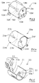
- Figure 3 shows a perspective view of a housing of a male connector;
- Figure 4 shows a perspective view of a male shielding shell;
- Figure 5 shows a perspective view of a shielding cover;
- Figure 6 shows a partially cut-away side view of the male connector of Figure 1 at a first intermediate assembly stage;
- Figure 7 shows a partially cut-away side view of the male connector of Figure 1 at a second intermediate assembly stage;
- Figure 8 shows a perspective view of a housing of a female connector;
- Figure 9 shows a perspective view of a female shielding shell;
- Figure 10 shows a partially cut-away side view of the female connector of Figure 1 at a first intermediate assembly stage;
- Figure 11 shows a partially cut-away side view of the female connector of Figure 1 at a second intermediate assembly stage; and
- Figure 12 shows a longitudinal cross-section of prior art shielded male and female connectors.
- A conventional shielded connector is shown in Figure 12. A
terminal 4 is connected to the end of awire core 3 exposed beyond ashielding layer 2 of a shieldedelectric cable 1. Theterminal 4 is inserted into aconnector housing 5 which is itself fitted into theouter end 7 of an electricallyconductive shielding cover 6. The inner end of the shielding cover is crimped to theshielding layer 2. - In a shielded connector, the
terminals 4 are inserted one by one into apertures of theconnector housing 5 from the rear. In order to place the second andsubsequent terminals 4 in the respective apertures, the length ofwire core 3 exposed from theshielding layer 2 must be at least the same as the length of theterminal 4. Accordingly the final connector is rather long, as illustrated, the relatively long exposedwire core 3 being necessary only for assembly reasons. - Male and
female connectors - The
male connector 10M comprises a cylindrical connector housing 11M of plastics material. - A shielded cable W is provided, comprising a plurality of plastic coated core wires Wa, a tubular shielding layer Wb covering the cores Wa, and an external covering Wc of plastics material surrounding the shielding layer Wb. In the present example, three cores Wa are provided. The shielding layer Wb is formed by intertwining of wires about the cores Wa.
- A plurality of
cavities 12M extend through thehousing 11M parallel with the axis thereof.Male terminals 45M are provided, and eachterminal 45M is crimped to a respective core Wa of the shielded cable W. The cable W is prepared for crimping of aterminal 45M to a core Wa thereof by stripping off a length of the external covering Wc to expose the shielding layer Wb, and turning back the shielding layer Wb to expose the cores Wa. Eachterminal 45M is housed in acavity 12M by insertion from a rear side of thehousing 11M. - The
male terminal 45M includes apin 46M for insertion in afemale terminal 45F of thefemale connector 10F. Thepin 46M extends from the front side of the housing when theterminal 45M is inserted in thecavity 12M. - After insertion of the
first terminal 45M into thehousing 11M, it is necessary to manoeuvre the second andsubsequent terminals 45M into the insertion position on the rear side of thehousing 11M. Consequently the length of wire core Wa which must be exposed from within the shielding layer Wb to allow such manoeuvring into position is greater than the length of theterminal 45M. - Two axially extending
ribs 13M are formed on the external periphery of thehousing 11M. Theribs 13M extend from the rear side of thehousing 11M, for approximately half the length thereof, and an angle of about 90° is subtended at the longitudinal axis of the housing. - Two
fitting projections 14M project radially from the external periphery of thehousing 11M, adjacent the rear end thereof. Thefitting projections 14M are each substantially diametrically opposite arespective rib 13M. Eachfitting projection 14M has alateral projection 15M extending from the end thereof distal thehousing 11M. As shown in Figure 3, thelateral projection 15M is disc-shaped. - The front face of the
housing 11M has two position-fixingrectangular recesses 16M defined therein. Therecesses 16M each extend from the circumference of the face and are diametrically opposed. - A tubular
metal shielding shell 20M is fitted coaxially over thehousing 11M, and has substantially the same length as thehousing 11M. Theshell 20M has an internal diameter substantially the same as the external diameter of thehousing 11M and is resiliently fitted over thehousing 11M.Blind guide slots 21M extend from the rear end of theshell 20M, corresponding to theribs 13M. Accordingly, when theshell 20M is fitted onto thehousing 11M, theribs 13M fit into theguide slots 21M. When the end of eachrib 13M which is farthest the rear face of thehousing 11M abuts the blind end of the respective slot, theshell 20M is properly aligned on thehousing 11M with the respective ends of thehousing 11M andshell 20M being flush. As a result, movement of theshell 20M relative thehousing 11M beyond the correct position is prevented. Theslots 21M are formed with inwardly projectingteeth 22M which engage theribs 13M to prevent removal of theshell 20M from thehousing 11M. - Two cut-
outs 23M are formed in the rear end of theshell 20M to accommodate thefitting projections 14M. Fourcontact tabs 24M extend axially from the front end of theshell 20M; thetabs 24M are equispaced. - A shielding
cover 30 is formed from sheet metal material. As shown in Figure 5, thecover 30 comprises a semi-cylindricalmain body 31 and a crimpingmember 32 extending from a rear end of themain body 31. The interior diameter of themain body 31 is substantially the same as the external diameter of theshell 20M. - Fitting
slots 33 extend from the front end (i.e. the end opposite the crimpingmember 32 of themain body 31, and corresponding to thefitting projections 14M of thehousing 11M. Eachfitting slot 33 comprises an axially extendinginsertion portions 33a, a transversemedial portion 33b and areturn portion 33c substantially perpendicular to or at an acute angle to themedial portion 33b. Accordingly, thefitting projections 14M of thehousing 11M and thefitting slots 33 of thecover 30 define a bayonet type fitting. - The crimping
member 32 comprises an in-turn portion 32a which extends radially inwardly, and abarrel member 32b comprising crimpingteeth 32c. In use, the shielding layer Wb of a shielded cable W is laid in the barrel member and the crimpingteeth 32c are crimped thereon to form an electrical contact between the shielding layer Wb and thecover 30. By virtue of the in-turn portion 32a, the cable W is substantially co-axial with thecover 30. - The above-described components of the
male connector 10M are housed in a generallytubular casing 40M. Position-fixing projections (not shown in the drawings) are formed on the inner side of the anterior end of thecasing 40M. These projections fit with therecesses 16M of theconnector housing 11M. By means of the projections engaging with therecesses 16M, thehousing 11M is retained from sliding right through thecasing 40M. Moreover, a radially internally extendinglance 41M prevents removal of thehousing 11M from thecasing 40M. - The
casing 40M has atubular entry portion 42M at its front end (corresponding to the front end of thehousing 11M). Theentry portion 42M is adapted to guide and receive a corresponding portion of afemale connector 10F therein. Lockingholes 43M are formed in the wall of theentry portion 42M to receive corresponding locking portions of thefemale connector 10F. - The
female connector 10F will now be described. It will be appreciated that many parts and features of that connector are substantially the same as those of themale connector 10M. Accordingly, only those features which are not common to both connectors are described. The components of thefemale connector 10F correspond to respective components of the male connectors, and therefore the suffix 'F' is substituted for 'M' where this is appropriate. Thefemale connector 10F comprises a shieldingcover 30 identical to that described above with reference to the male connector, and so further description in relation to that component is omitted. - As shown in Figure 8, the
connector housing 11F of thefemale connector 10F has fourindentations 17F defined therein, corresponding to the fourcontact tabs 24M of themale connector 10M. Theshell 20F also has fourinward indentations 24F corresponding and locating with theindentations 17F of thehousing 11F. Thecontact tabs 24M andindentations 24F are arranged to engage with each other for electrical contact of theshells connectors - As shown in Figure 1, the
casing 40F of thefemale connector 10F includes a locking arm 43F with a projection 44F adapted to engage thelocking hole 43M of themale connector 10M. - As shown in Figure 6, assembly of a
male connector 10M is performed by firstly crimping a male terminal 45M onto each core Wa of the shielded cable W, secondly crimping thecover 30 to the shielding layer Wb, thirdly inserting eachmale terminal 45M into thehousing 11M, and fourthly drawing theshell 20M and cover 30 together to create engagement by bayonet fit and electrical contact therebetween. The cores Wa will fold during drawing of the shell and cover together, and the resilience of the cores Wa tends to retain the bayonet fitting of theshell 20M and cover 30 by urging them axially apart. Figure 6 illustrates the connector after the third step, and Figure 7 after the fourth step. - By folding the core Wa, the overall length of the connector can be reduced. For example, in Figure 7, the core Wa is illustrated as occupying length S of the longitudinal length of the
connector 10M, which is substantially less than the overall exposed length L of the core Wa. - After assembly in the specified manner, the assembly is placed in the
casing 40M. Water seals 50 and 51 which were pre-threaded on the cable Wa are inserted in the rear end of thecasing 40M. An O-ring can be inserted to seal the entry portion. - The
female connector 10F is assembled in corresponding manner. In the same way, thefemale connector 10F is of substantially reduced length relative to other connectors since the cores Wa are folded: the length S occupied by the core Wa after assembly is less than the length L occupied by the core Wa before assembly. - Even though, in the specified embodiment, the
main body 31 of thecover 30 is semi-cylindrical, and so the wire core Wa is not totally shielded, the fact that the cores are all folded and compacted in a small space means that such incomplete shielding does not significantly adversely affect the performance of the connector. Alternatively themain body 31 could be completely tubular. Furthermore, the shieldingshells cores 30 be increased in length so as to directly shield thehousings
Claims (9)
- An electrical connector for a shielded electrical cable, said connector having a housing (11M,11F) of insulating material, an electrically conducting terminal (45M,45F) within the housing (11M,11F) and a shielding cover (30) for the housing (11M,11F), wherein the terminal (45M,45F) is adapted to be connected to a core wire (Wa) of a cable (W) and the shielding cover (30) is adapted to be connected to the shielding layer (Wb) of a cable (W), the housing (11M,11F) and shielding cover (30) being relatively movable from a first condition in which the housing (11M,11F) and cover (30) are spaced apart to a second condition in which the cover (30) overlaps the housing (11M,11F).
- The connector of claim 1 wherein the housing (11M,11F) has an electrically conductive outer shell (20M,20F).
- The connector of claim 2 wherein in the second condition, the cover (30) and shell (20M,20F) establish an electrical contact therebetween.
- The connector of any preceding claim wherein the housing (11M,11F) and cover (30) are engageable in the second condition.
- The connector of any preceding claim wherein one of the housing (11M,11F) and the cover (30) includes a projection (14M,14F) engageable in a channel (33) of the other of the housing (11M,11F) and the cover (30).
- The connector of claim 5 wherein the projection (14M,14F) and channel (33) constitute a bayonet fitting.
- The connector of any preceding claim wherein the housing is cylindrical (11M,11F) and the cover is arcuate (30).
- The connector of any preceding claim further comprising a casing (40M,40F) to receive and retain the housing (11M,11F) and cover (30) therein.
- The connector of any preceding claim and further including a shielded electrical cable (W) attached thereto, the core wire (Wa) of the cable (W) being foldable in the second condition to exert a resilient force which, in use, urges the cover (30) and housing (11M,11F) apart.
Applications Claiming Priority (3)
| Application Number | Priority Date | Filing Date | Title |
|---|---|---|---|
| JP7196068A JP2910631B2 (en) | 1995-07-07 | 1995-07-07 | Shield connector |
| JP196068/95 | 1995-07-07 | ||
| JP19606895 | 1995-07-07 |
Publications (3)
| Publication Number | Publication Date |
|---|---|
| EP0752737A2 true EP0752737A2 (en) | 1997-01-08 |
| EP0752737A3 EP0752737A3 (en) | 1998-11-04 |
| EP0752737B1 EP0752737B1 (en) | 2001-10-31 |
Family
ID=16351670
Family Applications (1)
| Application Number | Title | Priority Date | Filing Date |
|---|---|---|---|
| EP96304458A Expired - Lifetime EP0752737B1 (en) | 1995-07-07 | 1996-06-14 | Shielded connector |
Country Status (5)
| Country | Link |
|---|---|
| US (1) | US5791939A (en) |
| EP (1) | EP0752737B1 (en) |
| JP (1) | JP2910631B2 (en) |
| CN (1) | CN1151088A (en) |
| DE (1) | DE69616441T2 (en) |
Cited By (5)
| Publication number | Priority date | Publication date | Assignee | Title |
|---|---|---|---|---|
| EP0827238A2 (en) * | 1996-08-28 | 1998-03-04 | Sumitomo Wiring Systems, Ltd. | Self-aligning and locking shielded connector |
| EP0935312A2 (en) * | 1998-02-04 | 1999-08-11 | Hirose Electric Co., Ltd. | Electrical connector system |
| EP0993075A2 (en) * | 1998-10-05 | 2000-04-12 | Hirose Electric Co., Ltd. | Electrical connector with metallic jacket |
| EP2071676A2 (en) * | 2007-12-14 | 2009-06-17 | Quirin Grawe | Connector assembly |
| EP2112722A1 (en) * | 2008-04-24 | 2009-10-28 | Radiall | Hybrid connector with a plurality of cantacts |
Families Citing this family (17)
| Publication number | Priority date | Publication date | Assignee | Title |
|---|---|---|---|---|
| JPH11102752A (en) * | 1997-09-29 | 1999-04-13 | Yazaki Corp | Shielded connector |
| JP3675134B2 (en) * | 1997-10-21 | 2005-07-27 | 矢崎総業株式会社 | Shield connector |
| JP3229272B2 (en) * | 1998-10-21 | 2001-11-19 | ヒロセ電機株式会社 | Shield connector |
| JP3841351B2 (en) * | 2003-05-19 | 2006-11-01 | 日本航空電子工業株式会社 | connector |
| JP5003583B2 (en) * | 2008-04-25 | 2012-08-15 | オムロン株式会社 | connector |
| DE102010002681B4 (en) * | 2010-03-09 | 2018-10-18 | Te Connectivity Germany Gmbh | Electrical connector, electrical connector and assembled electrical cable |
| JP6582649B2 (en) * | 2015-07-10 | 2019-10-02 | 株式会社オートネットワーク技術研究所 | Shield structure |
| US10128613B2 (en) * | 2015-10-29 | 2018-11-13 | Puleo International Inc. | Pin connector assembly |
| DE102017213150A1 (en) * | 2017-07-31 | 2019-01-31 | Robert Bosch Gmbh | Electrical plug contact for high current applications and connector system for high current applications |
| US10505322B2 (en) * | 2018-01-19 | 2019-12-10 | Te Connectivity Corporation | Communication system having coaxial connector assembly |
| US10505323B2 (en) | 2018-01-19 | 2019-12-10 | Te Connectivity Corporation | Communication system having coaxial connector assembly |
| US10558000B2 (en) | 2018-01-22 | 2020-02-11 | Te Connectivity Corporation | Communication system having coaxial connector module and fiber optic module |
| CN109616834A (en) * | 2018-12-13 | 2019-04-12 | 上海航天科工电器研究院有限公司 | One kind having the quick locking wire water-proof connector of shielding construction |
| US10498061B1 (en) | 2018-12-17 | 2019-12-03 | Te Connectivity Corporation | Coaxial connector assembly |
| US11025006B2 (en) | 2019-09-04 | 2021-06-01 | Te Connectivity Corporation | Communication system having connector assembly |
| CN112952425A (en) * | 2019-12-11 | 2021-06-11 | 富士康(昆山)电脑接插件有限公司 | Electric connector combination |
| DE102022203219B4 (en) | 2022-03-31 | 2024-03-28 | Yamaichi Electronics Deutschland Gmbh | Circular connector |
Citations (5)
| Publication number | Priority date | Publication date | Assignee | Title |
|---|---|---|---|---|
| US3753215A (en) * | 1971-04-12 | 1973-08-14 | Us Navy | Cable connector |
| EP0328234A2 (en) * | 1988-02-08 | 1989-08-16 | Cinch Connectors Limited | Shielded cable connector |
| US5222909A (en) * | 1991-09-12 | 1993-06-29 | Yazaki Corporation | Demountable shield connector |
| US5232380A (en) * | 1991-09-07 | 1993-08-03 | Sumitomo Wiring Systems, Ltd. | Shield cover for electric connector |
| JPH05258801A (en) * | 1991-12-25 | 1993-10-08 | Sumitomo Wiring Syst Ltd | Waterproof shield connector |
Family Cites Families (2)
| Publication number | Priority date | Publication date | Assignee | Title |
|---|---|---|---|---|
| JPH0140140Y2 (en) * | 1985-05-13 | 1989-12-01 | ||
| US5628653A (en) * | 1996-03-12 | 1997-05-13 | Regal Electronics, Inc. | Shielded modular adapter |
-
1995
- 1995-07-07 JP JP7196068A patent/JP2910631B2/en not_active Expired - Fee Related
-
1996
- 1996-06-14 EP EP96304458A patent/EP0752737B1/en not_active Expired - Lifetime
- 1996-06-14 DE DE69616441T patent/DE69616441T2/en not_active Expired - Fee Related
- 1996-07-03 US US08/674,804 patent/US5791939A/en not_active Expired - Lifetime
- 1996-07-04 CN CN96106943A patent/CN1151088A/en active Pending
Patent Citations (5)
| Publication number | Priority date | Publication date | Assignee | Title |
|---|---|---|---|---|
| US3753215A (en) * | 1971-04-12 | 1973-08-14 | Us Navy | Cable connector |
| EP0328234A2 (en) * | 1988-02-08 | 1989-08-16 | Cinch Connectors Limited | Shielded cable connector |
| US5232380A (en) * | 1991-09-07 | 1993-08-03 | Sumitomo Wiring Systems, Ltd. | Shield cover for electric connector |
| US5222909A (en) * | 1991-09-12 | 1993-06-29 | Yazaki Corporation | Demountable shield connector |
| JPH05258801A (en) * | 1991-12-25 | 1993-10-08 | Sumitomo Wiring Syst Ltd | Waterproof shield connector |
Non-Patent Citations (1)
| Title |
|---|
| PATENT ABSTRACTS OF JAPAN vol. 018, no. 020 (E-1489), 13 January 1994 & JP 05 258801 A (SUMITOMO WIRING SYST LTD), 8 October 1993 * |
Cited By (12)
| Publication number | Priority date | Publication date | Assignee | Title |
|---|---|---|---|---|
| EP0827238A2 (en) * | 1996-08-28 | 1998-03-04 | Sumitomo Wiring Systems, Ltd. | Self-aligning and locking shielded connector |
| EP0827238A3 (en) * | 1996-08-28 | 1999-10-27 | Sumitomo Wiring Systems, Ltd. | Self-aligning and locking shielded connector |
| EP0935312A2 (en) * | 1998-02-04 | 1999-08-11 | Hirose Electric Co., Ltd. | Electrical connector system |
| EP0935312A3 (en) * | 1998-02-04 | 2000-11-08 | Hirose Electric Co., Ltd. | Electrical connector system |
| US6283793B1 (en) | 1998-02-04 | 2001-09-04 | Hirose Electric Co., Ltd. | Electrical connector system |
| EP0993075A2 (en) * | 1998-10-05 | 2000-04-12 | Hirose Electric Co., Ltd. | Electrical connector with metallic jacket |
| EP0993075A3 (en) * | 1998-10-05 | 2001-03-21 | Hirose Electric Co., Ltd. | Electrical connector with metallic jacket |
| EP2071676A2 (en) * | 2007-12-14 | 2009-06-17 | Quirin Grawe | Connector assembly |
| EP2071676A3 (en) * | 2007-12-14 | 2012-05-02 | Quirin Grawe | Connector assembly |
| EP2112722A1 (en) * | 2008-04-24 | 2009-10-28 | Radiall | Hybrid connector with a plurality of cantacts |
| FR2930686A1 (en) * | 2008-04-24 | 2009-10-30 | Radiall Sa | HYBRID MULTI-CONTACTS CONNECTOR |
| US7942588B2 (en) | 2008-04-24 | 2011-05-17 | Radiall | Hybrid multi-contact connector |
Also Published As
| Publication number | Publication date |
|---|---|
| CN1151088A (en) | 1997-06-04 |
| EP0752737B1 (en) | 2001-10-31 |
| DE69616441D1 (en) | 2001-12-06 |
| DE69616441T2 (en) | 2002-06-27 |
| US5791939A (en) | 1998-08-11 |
| EP0752737A3 (en) | 1998-11-04 |
| JP2910631B2 (en) | 1999-06-23 |
| JPH0922755A (en) | 1997-01-21 |
Similar Documents
| Publication | Publication Date | Title |
|---|---|---|
| EP0752737B1 (en) | Shielded connector | |
| EP2610975B1 (en) | Unit comprising a wire fixing member and method of assembling it | |
| US5180316A (en) | Shielded electrical connector | |
| US5831815A (en) | Programmable backshell for an electrical connector | |
| EP1630905B1 (en) | Multiphase connector | |
| EP3203586B1 (en) | Electrical connector | |
| EP1744409B1 (en) | A shielded connector and method of connecting it with a shielded cable | |
| US5645450A (en) | Shielded connector | |
| EP1548899A1 (en) | A shielded connector | |
| US5489222A (en) | Mini connector with anti-rotational contact | |
| GB2273400A (en) | Shielded connector | |
| US5904595A (en) | Self-aligning and locking shielded connector | |
| JP2568909B2 (en) | Electrical connector | |
| EP0654860B1 (en) | Waterproofing assembly for connector | |
| JP2603371Y2 (en) | Waterproof stopper and wire terminal with waterproof stopper | |
| EP0993075A2 (en) | Electrical connector with metallic jacket | |
| JP2021018979A (en) | Waterproof shield connector | |
| WO2006044514A1 (en) | Round shielded-connector | |
| JP6933192B2 (en) | Conductive path and connector device | |
| JP3281597B2 (en) | Termination structure of shielded wires | |
| EP3336970B1 (en) | Electrical connector and method of assembling an electrical connector to a cable | |
| JP3344622B2 (en) | Shielded wire connector | |
| CN218448613U (en) | Connector and connector assembly | |
| WO2023181970A1 (en) | Shield unit | |
| JP3126287B2 (en) | Method of connecting shielded electric wire to connector and connector structure |
Legal Events
| Date | Code | Title | Description |
|---|---|---|---|
| PUAI | Public reference made under article 153(3) epc to a published international application that has entered the european phase |
Free format text: ORIGINAL CODE: 0009012 |
|
| AK | Designated contracting states |
Kind code of ref document: A2 Designated state(s): DE FR GB |
|
| 17P | Request for examination filed |
Effective date: 19970210 |
|
| PUAL | Search report despatched |
Free format text: ORIGINAL CODE: 0009013 |
|
| AK | Designated contracting states |
Kind code of ref document: A3 Designated state(s): DE FR GB |
|
| 17Q | First examination report despatched |
Effective date: 19991203 |
|
| GRAG | Despatch of communication of intention to grant |
Free format text: ORIGINAL CODE: EPIDOS AGRA |
|
| GRAG | Despatch of communication of intention to grant |
Free format text: ORIGINAL CODE: EPIDOS AGRA |
|
| GRAH | Despatch of communication of intention to grant a patent |
Free format text: ORIGINAL CODE: EPIDOS IGRA |
|
| GRAH | Despatch of communication of intention to grant a patent |
Free format text: ORIGINAL CODE: EPIDOS IGRA |
|
| GRAA | (expected) grant |
Free format text: ORIGINAL CODE: 0009210 |
|
| RIC1 | Information provided on ipc code assigned before grant |
Free format text: 7H 01R 9/05 A, 7H 01R 13/658 B, 7H 01R 13/625 B |
|
| AK | Designated contracting states |
Kind code of ref document: B1 Designated state(s): DE FR GB |
|
| REF | Corresponds to: |
Ref document number: 69616441 Country of ref document: DE Date of ref document: 20011206 |
|
| REG | Reference to a national code |
Ref country code: GB Ref legal event code: IF02 |
|
| ET | Fr: translation filed | ||
| PG25 | Lapsed in a contracting state [announced via postgrant information from national office to epo] |
Ref country code: GB Free format text: LAPSE BECAUSE OF NON-PAYMENT OF DUE FEES Effective date: 20020614 |
|
| PLBE | No opposition filed within time limit |
Free format text: ORIGINAL CODE: 0009261 |
|
| STAA | Information on the status of an ep patent application or granted ep patent |
Free format text: STATUS: NO OPPOSITION FILED WITHIN TIME LIMIT |
|
| 26N | No opposition filed | ||
| PG25 | Lapsed in a contracting state [announced via postgrant information from national office to epo] |
Ref country code: DE Free format text: LAPSE BECAUSE OF NON-PAYMENT OF DUE FEES Effective date: 20030101 |
|
| GBPC | Gb: european patent ceased through non-payment of renewal fee |
Effective date: 20020614 |
|
| PG25 | Lapsed in a contracting state [announced via postgrant information from national office to epo] |
Ref country code: FR Free format text: LAPSE BECAUSE OF NON-PAYMENT OF DUE FEES Effective date: 20030228 |
|
| REG | Reference to a national code |
Ref country code: FR Ref legal event code: ST |