EP0993075A2 - Electrical connector with metallic jacket - Google Patents
Electrical connector with metallic jacket Download PDFInfo
- Publication number
- EP0993075A2 EP0993075A2 EP99650090A EP99650090A EP0993075A2 EP 0993075 A2 EP0993075 A2 EP 0993075A2 EP 99650090 A EP99650090 A EP 99650090A EP 99650090 A EP99650090 A EP 99650090A EP 0993075 A2 EP0993075 A2 EP 0993075A2
- Authority
- EP
- European Patent Office
- Prior art keywords
- metallic jacket
- tubular support
- electrical connector
- slit
- stopper
- Prior art date
- Legal status (The legal status is an assumption and is not a legal conclusion. Google has not performed a legal analysis and makes no representation as to the accuracy of the status listed.)
- Withdrawn
Links
Images


Classifications
-
- H—ELECTRICITY
- H01—ELECTRIC ELEMENTS
- H01R—ELECTRICALLY-CONDUCTIVE CONNECTIONS; STRUCTURAL ASSOCIATIONS OF A PLURALITY OF MUTUALLY-INSULATED ELECTRICAL CONNECTING ELEMENTS; COUPLING DEVICES; CURRENT COLLECTORS
- H01R9/00—Structural associations of a plurality of mutually-insulated electrical connecting elements, e.g. terminal strips or terminal blocks; Terminals or binding posts mounted upon a base or in a case; Bases therefor
- H01R9/03—Connectors arranged to contact a plurality of the conductors of a multiconductor cable, e.g. tapping connections
- H01R9/05—Connectors arranged to contact a plurality of the conductors of a multiconductor cable, e.g. tapping connections for coaxial cables
- H01R9/0518—Connection to outer conductor by crimping or by crimping ferrule
Definitions
- the present invention relates to electrical connectors with a metallic jacket.
- Fig. 4 shows conventional coaxial electrical connector which comprises an insulating tubular support 52 and an inner sheath 51 supported by the tubular support 52.
- a mouth 53 is provided at a front end of the tubular support 52 for receiving a pin-like male contact element of a mating connector for connection.
- a pair of semi-cylindrical members 55 hinged at 54 is provided on the rear section of the tubular support 52. By opening the hinged semi-cylindrical members 55 the female contact element is placed at a predetermined position and by closing them it is held in place.
- a stopper projection 56 is provided on the tubular support 52 in front of the hinge 54.
- a metallic outer conductive shell or jacket 57 is able to fit over the tubular support 52, when the shielded wires are connected to the outer conductive shell 57 via the metallic sleeve.
- a plurality of slits 58 extend rearwardly from a front opening of the outer conductive shell 57 so that the outer conductive shell 57 can flex outwardly to assure contact with the outer conductor of a mating connector.
- a stopper hole 59 is provided at a middle of the outer conductive shell 57 for engagement with the stopper projection 56 of the tubular support 52 to prevent separation of the tubular support 52. In this embodiment, one or a pair of the stopper holes 59 are provided in line with one or a pair of the opposed slits 58.
- a pair of crimping pieces 60 and 61 are provided on the outer conductive shell 57 at the rear portion to hold the shield wire and the outer sheath, respectively.
- the stopper hole 59 of the outer conductive shell 57 is not always aligned with the slit 58 so that it is always necessary to check if the stopper projection 56 and the stopper hole 59 are aligned before assembling.
- the stopper projection 56 can advance easily up to the end of the slits 58 because the outer conductive shell 57 is easily flexed owing to the slits 58, but hardly advance from the end of the slits 58 to the stopper hole 59.
- Fig. 1 shows an electrical connector being assembled according to an embodiment of the invention and Fig. 2 shows in section the assembled electrical connector.
- a coaxial cable C has a central conductor C1, an insulating inner sheath C2, shield wires C3, and an insulating outer sheath C4.
- the shield wires C3 and the outer sheath C4 are omitted.
- the central conductor C1 projecting from the inner sheath C2 is connected to a contact element 1.
- the contact element 1 is of the female type and has a contact section 2 at a front end for receiving a male contact element.
- the contact section 2 is made flexible and has a tapered portion 3 for guiding the male contact element.
- the contact element 1 and the inner sheath C2 are supported by a tubular support 4 of a dielectric material.
- the tubular support 4 has a pair of semi-cylindrical rear sections 6 which are joined together with a hinge 5. After the contact element 1 is placed at a predetermined position in the opened semi-cylindrical rear sections 6, the rear sections 6 are closed and locked to support the contact element 1 and the inner sheath C2.
- a pair of stopper projections 7 are provided on the tubular support 4 at diagonal positions. As best shown in Fig. 2, the stopper projection 7 has a front vertical stopper face 7B and a rear sloped guiding face 7A.
- a check window 8 is provided in the tubular support 4 at a position corresponding to the tapered portion 3 of the contact element 1 to not only permit checking if the contact element 1 is placed at the regular position but also enlarge the space where the tapered portion 3 can expand to facilitate insertion of the male contact element.
- a mouth 9 at the front end of the tubular support 4 is also tapered to facilitate insertion of the male contact element.
- a metallic sleeve 10 is provided to connect the shield wires C3. It has a tubular section 11 and a conical section 12. A circular projection 13 is provided on the tubular section 11. It may be one or a series of projections provided on a circumference. The inside diameter of the tubular section 11 is set at such a value that the metallic sleeve 10 can slide on the inner sheath C2 of the cable.
- the outer conductive shell or jacket 14 has a tubular section 15 and a rear crimping pieces 16 and 17 to hold the shield wires and the outer sheath, respectively.
- a plurality of slits 18 extend rearwardly from the front opening of the tubular section 15.
- a pair of stopper holes 19 communicate with the two diagonally positioned slits 18.
- the stopper hole may be an indentation which is wider than the slit to provide shoulders for engagement with the stopper projection.
- the stopper projection may be omitted by making the hinge work as a stopper projection. In this case, the stopper hole is modified so as to adapt to it.
- slits are conceivable.
- the width of a slit 18A communicating with the stopper hole 19 is greater than the width of a slit 18 so that the slits 18 and 18A are distinguished easily while the stopper projection is guided easily.
- the inside edges 18B of the slit 18A are tapered.
- the corners 18C of the slit 18A are tapered.
- the stopper projection is guided to the stopper hole once the stopper projection is aligned with the slit, eliminating the need to search for the stopper hole before assembling.
- the engagement is made firm but also the operation is made easy.
Abstract
Description
- The present invention relates to electrical connectors with a metallic jacket.
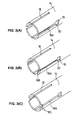
- Fig. 4 shows conventional coaxial electrical connector which comprises an insulating
tubular support 52 and aninner sheath 51 supported by thetubular support 52. Amouth 53 is provided at a front end of thetubular support 52 for receiving a pin-like male contact element of a mating connector for connection. A pair ofsemi-cylindrical members 55 hinged at 54 is provided on the rear section of thetubular support 52. By opening the hingedsemi-cylindrical members 55 the female contact element is placed at a predetermined position and by closing them it is held in place. Astopper projection 56 is provided on thetubular support 52 in front of thehinge 54. - A metallic outer conductive shell or
jacket 57 is able to fit over thetubular support 52, when the shielded wires are connected to the outerconductive shell 57 via the metallic sleeve. A plurality ofslits 58 extend rearwardly from a front opening of the outerconductive shell 57 so that the outerconductive shell 57 can flex outwardly to assure contact with the outer conductor of a mating connector. Astopper hole 59 is provided at a middle of the outerconductive shell 57 for engagement with thestopper projection 56 of thetubular support 52 to prevent separation of thetubular support 52. In this embodiment, one or a pair of thestopper holes 59 are provided in line with one or a pair of theopposed slits 58. A pair ofcrimping pieces conductive shell 57 at the rear portion to hold the shield wire and the outer sheath, respectively. - However, the
stopper hole 59 of the outerconductive shell 57 is not always aligned with theslit 58 so that it is always necessary to check if thestopper projection 56 and thestopper hole 59 are aligned before assembling. Thestopper projection 56 can advance easily up to the end of theslits 58 because the outerconductive shell 57 is easily flexed owing to theslits 58, but hardly advance from the end of theslits 58 to thestopper hole 59. - Accordingly, it is an object of the invention to provide an electrical connector with a metallic shell enabling to assemble it easily.
- The above object is achieved by the invention claimed in
claim 1. - Embodiments of the invention will now be described by way of example with reference to accompanying drawings, in which:
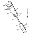
- Fig. 1 is a perspective view of an electrical connector being assembled according to an embodiment of the invention;
- Fig. 2 is a sectional view the completed electrical connector;
- Figs. 3(A)-(C) are perspective views of different slits; and
- Fig. 4 is a perspective view of a conventional electrical connector.
-
- Fig. 1 shows an electrical connector being assembled according to an embodiment of the invention and Fig. 2 shows in section the assembled electrical connector. A coaxial cable C has a central conductor C1, an insulating inner sheath C2, shield wires C3, and an insulating outer sheath C4. In Fig. 1, the shield wires C3 and the outer sheath C4 are omitted. The central conductor C1 projecting from the inner sheath C2 is connected to a
contact element 1. In this embodiment, thecontact element 1 is of the female type and has acontact section 2 at a front end for receiving a male contact element. Thecontact section 2 is made flexible and has atapered portion 3 for guiding the male contact element. - The
contact element 1 and the inner sheath C2 are supported by atubular support 4 of a dielectric material. Thetubular support 4 has a pair of semi-cylindrical rear sections 6 which are joined together with ahinge 5. After thecontact element 1 is placed at a predetermined position in the opened semi-cylindrical rear sections 6, the rear sections 6 are closed and locked to support thecontact element 1 and the inner sheath C2. - A pair of
stopper projections 7 are provided on thetubular support 4 at diagonal positions. As best shown in Fig. 2, thestopper projection 7 has a frontvertical stopper face 7B and a rear sloped guiding face 7A. Acheck window 8 is provided in thetubular support 4 at a position corresponding to thetapered portion 3 of thecontact element 1 to not only permit checking if thecontact element 1 is placed at the regular position but also enlarge the space where thetapered portion 3 can expand to facilitate insertion of the male contact element. A mouth 9 at the front end of thetubular support 4 is also tapered to facilitate insertion of the male contact element. - A
metallic sleeve 10 is provided to connect the shield wires C3. It has atubular section 11 and aconical section 12. Acircular projection 13 is provided on thetubular section 11. It may be one or a series of projections provided on a circumference. The inside diameter of thetubular section 11 is set at such a value that themetallic sleeve 10 can slide on the inner sheath C2 of the cable. The outer conductive shell orjacket 14 has atubular section 15 and arear crimping pieces slits 18 extend rearwardly from the front opening of thetubular section 15. A pair ofstopper holes 19 communicate with the two diagonally positionedslits 18. - How to assemble the electrical connector will be described below.
- (1) A predetermined length of the insulating outer sheath C4 is removed from the coaxial cable C to expose the shield wires C3.
- (2) The
metallic sleeve 10 is inserted into a space between the shield wires C3 and the inner sheath C2 until only theconical portion 12 is exposed. A part of the shield wires C3 is raised by thecircular projection 13 of thetubular section 11 so that thetubular section 11 is not moved in the axial direction. - (3) Then, the central conductor C1 of the cable is
connected to the
contact element 1. - (4) The semi-cylindrical rear sections 6 of the
tubular support 4 are opened, and thecontact element 1 is placed at a predetermined position. Then, the rear sections 6 are closed and locked to hold thecontact element 1 and the inner sheath C2, thereby providing the structure as shown in Fig. 1. - (5) Then, the
tubular support 4 is inserted into theouter conductor shell 14 such that thestopper projection 7 is aligned with theslit 18 which communicates with thestopper hole 19. Thestopper projection 7 is guided by theslit 18 to thestopper hole 19 where thestopper face 7B of thestopper projection 7 engages ashoulder 20 of thestopper hole 19. This completes assembling of thetubular support 4 and theouter conductor shell 14. - (6) Then, the
crimping pieces conductive shell 14 are deformed to hold the shield wires C3 and theouter sheath 17, thereby providing a structure as shown in Fig. 2. -
- Alternatively, the stopper hole may be an indentation which is wider than the slit to provide shoulders for engagement with the stopper projection. The stopper projection may be omitted by making the hinge work as a stopper projection. In this case, the stopper hole is modified so as to adapt to it.
- Various types of the slit are conceivable. In Fig. 3(A), the width of a
slit 18A communicating with thestopper hole 19 is greater than the width of aslit 18 so that theslits inside edges 18B of theslit 18A are tapered. In Fig. 3(C), thecorners 18C of theslit 18A are tapered. These slits have the same advantages as the slit of Fig. 3(A). - Since the stopper hole communicates with the slit, the stopper projection is guided to the stopper hole once the stopper projection is aligned with the slit, eliminating the need to search for the stopper hole before assembling. Thus, not only the engagement is made firm but also the operation is made easy.
Claims (6)
- An electrical connector with a metallic jacket, comprising:a contact element to be connected to a cable;a tubular support for supporting said contact element;a metallic jacket fitted over said tubular support and having at least one slit extending rearwardly from a front opening of said metallic jacket;a stopper projection provided on said tubular support; anda stopper portion communicating with said slit and having a shoulder for engagement with said stopper projection to lock said metallic jacket to said tubular support.
- An electrical connector with a metallic jacket according to claim 1, wherein said tubular support is made of a dielectric material while said metallic jacket is an outer conductive shell.
- An electrical connector with a metallic jacket according to claim 1, wherein there are provided four slits and said stopper portion communicates with at least one of said four slits.
- An electrical connector with a metallic jacket according to claim 1 or 3, wherein said slit communicating with said stopper portion is wider than said slit not communicating with said stopper portion.
- An electrical connector with a metallic jacket according to claim 1, 3, or 4, wherein said slit communicating with said stopper portion is tapered at inside edges or opening corners.
- An electrical connector with a metallic jacket according to claim 1 or 2, wherein said tubular support has a pair of semi-cylindrical rear sections joined with a hinge for opening/closing movement, said hinge also replacing said stopper projection.
Applications Claiming Priority (2)
| Application Number | Priority Date | Filing Date | Title |
|---|---|---|---|
| JP10296251A JP2000113946A (en) | 1998-10-05 | 1998-10-05 | Electric connector with metal outer tube body |
| JP29625198 | 1998-10-05 |
Publications (2)
| Publication Number | Publication Date |
|---|---|
| EP0993075A2 true EP0993075A2 (en) | 2000-04-12 |
| EP0993075A3 EP0993075A3 (en) | 2001-03-21 |
Family
ID=17831159
Family Applications (1)
| Application Number | Title | Priority Date | Filing Date |
|---|---|---|---|
| EP99650090A Withdrawn EP0993075A3 (en) | 1998-10-05 | 1999-09-29 | Electrical connector with metallic jacket |
Country Status (2)
| Country | Link |
|---|---|
| EP (1) | EP0993075A3 (en) |
| JP (1) | JP2000113946A (en) |
Cited By (5)
| Publication number | Priority date | Publication date | Assignee | Title |
|---|---|---|---|---|
| EP0991143A2 (en) * | 1998-09-28 | 2000-04-05 | Hirose Electric Co., Ltd. | Electrical connector with contact element |
| DE102004024792A1 (en) * | 2004-05-17 | 2005-12-15 | Ims Connector Systems Gmbh | Coaxial cable connector, has insert arranged so that outer conductor of cable only partially passes over it |
| DE102009016227A1 (en) * | 2009-04-03 | 2010-10-07 | Kostal Kontakt Systeme Gmbh | Connector for connection to a coaxial cable |
| CN104685728A (en) * | 2012-10-05 | 2015-06-03 | 矢崎总业株式会社 | Spacer for terminal |
| EP3242359A1 (en) * | 2016-05-04 | 2017-11-08 | MD Elektronik GmbH | Cable |
Families Citing this family (7)
| Publication number | Priority date | Publication date | Assignee | Title |
|---|---|---|---|---|
| JP4083103B2 (en) * | 2003-10-06 | 2008-04-30 | ホシデン株式会社 | Connector for coaxial cable |
| JP4616760B2 (en) * | 2004-12-17 | 2011-01-19 | ホシデン株式会社 | Coaxial connector |
| JP4606932B2 (en) * | 2005-04-22 | 2011-01-05 | 矢崎総業株式会社 | Coaxial cable, coaxial cable terminal processing structure, and shield terminal for coaxial cable |
| US9142895B2 (en) * | 2014-02-17 | 2015-09-22 | Tyco Electronics Corporation | Coaxial connector assembly |
| EP3220483A1 (en) | 2016-03-17 | 2017-09-20 | TE Connectivity Germany GmbH | Electric connection device, method of assembling an electrical cable and assembled electrical coaxial cable |
| US9871315B1 (en) * | 2017-04-05 | 2018-01-16 | Din Yi Industrial Co., Ltd. | Electrical connector for connection to a transmission connector on a device |
| US11791600B2 (en) * | 2020-12-16 | 2023-10-17 | Aptiv Technologies Limited | Barrel crimp retention feature for connector with braided wire |
Citations (3)
| Publication number | Priority date | Publication date | Assignee | Title |
|---|---|---|---|---|
| US3295094A (en) * | 1966-05-10 | 1966-12-27 | Amp Inc | Coaxial plug terminal |
| US4995836A (en) * | 1988-12-01 | 1991-02-26 | Hosiden Electronics Co., Ltd. | Pin plug connector |
| EP0752737A2 (en) * | 1995-07-07 | 1997-01-08 | Sumitomo Wiring Systems, Ltd. | Shielded connector |
-
1998
- 1998-10-05 JP JP10296251A patent/JP2000113946A/en active Pending
-
1999
- 1999-09-29 EP EP99650090A patent/EP0993075A3/en not_active Withdrawn
Patent Citations (3)
| Publication number | Priority date | Publication date | Assignee | Title |
|---|---|---|---|---|
| US3295094A (en) * | 1966-05-10 | 1966-12-27 | Amp Inc | Coaxial plug terminal |
| US4995836A (en) * | 1988-12-01 | 1991-02-26 | Hosiden Electronics Co., Ltd. | Pin plug connector |
| EP0752737A2 (en) * | 1995-07-07 | 1997-01-08 | Sumitomo Wiring Systems, Ltd. | Shielded connector |
Cited By (13)
| Publication number | Priority date | Publication date | Assignee | Title |
|---|---|---|---|---|
| EP0991143A2 (en) * | 1998-09-28 | 2000-04-05 | Hirose Electric Co., Ltd. | Electrical connector with contact element |
| EP0991143A3 (en) * | 1998-09-28 | 2001-05-02 | Hirose Electric Co., Ltd. | Electrical connector with contact element |
| US6336832B2 (en) | 1998-09-28 | 2002-01-08 | Hirose Electric Co., Ltd. | Electrical connector with female contact element |
| DE102004024792A1 (en) * | 2004-05-17 | 2005-12-15 | Ims Connector Systems Gmbh | Coaxial cable connector, has insert arranged so that outer conductor of cable only partially passes over it |
| DE102004024792B4 (en) * | 2004-05-17 | 2007-12-13 | Ims Connector Systems Gmbh | cable connectors |
| US8323055B2 (en) | 2009-04-03 | 2012-12-04 | Kostal Kontakt Systeme Gmbh | Plug-in connector for connecting to a coaxial cable |
| DE102009016227A1 (en) * | 2009-04-03 | 2010-10-07 | Kostal Kontakt Systeme Gmbh | Connector for connection to a coaxial cable |
| DE102009016227B4 (en) * | 2009-04-03 | 2017-12-28 | Kostal Kontakt Systeme Gmbh | Connector with a connected coaxial cable |
| CN104685728A (en) * | 2012-10-05 | 2015-06-03 | 矢崎总业株式会社 | Spacer for terminal |
| US9385465B2 (en) | 2012-10-05 | 2016-07-05 | Yazaki Corporation | Terminal spacer |
| CN104685728B (en) * | 2012-10-05 | 2016-12-21 | 矢崎总业株式会社 | Terminal sept |
| EP3242359A1 (en) * | 2016-05-04 | 2017-11-08 | MD Elektronik GmbH | Cable |
| US10074462B2 (en) | 2016-05-04 | 2018-09-11 | Md Elektronik Gmbh | Cable having a pluggable connector |
Also Published As
| Publication number | Publication date |
|---|---|
| JP2000113946A (en) | 2000-04-21 |
| EP0993075A3 (en) | 2001-03-21 |
Similar Documents
| Publication | Publication Date | Title |
|---|---|---|
| US5037328A (en) | Foldable dielectric insert for a coaxial contact | |
| US7494377B2 (en) | Electrical connector | |
| JP3356301B2 (en) | Coaxial contact and method of connecting it to coaxial cable | |
| US5393244A (en) | Twist-on coaxial cable end connector with internal post | |
| US4990105A (en) | Tapered lead-in insert for a coaxial contact | |
| US4269469A (en) | Contact terminal connector | |
| US4799902A (en) | Triaxial electrical cable connector | |
| US7044789B2 (en) | Electrical connector | |
| US5180316A (en) | Shielded electrical connector | |
| EP1641089B1 (en) | A connector provided with contacts mounted in an adapted insulator | |
| EP1548899A1 (en) | A shielded connector | |
| EP3203586B1 (en) | Electrical connector | |
| US20100297877A1 (en) | Coaxial connector and assembling method of coaxial connector | |
| JPH06243933A (en) | Shield type electric connector | |
| US20140017928A1 (en) | Lockable mating connector | |
| AU2007306960A1 (en) | XLR cable connector | |
| US7070440B1 (en) | Coaxial cable insulation displacement connector | |
| US4723916A (en) | Pin plug and socket connector using insulation displacement contacts | |
| EP0432144B1 (en) | Electrical connector assembly | |
| EP0993075A2 (en) | Electrical connector with metallic jacket | |
| US4842549A (en) | Dual diameter cable strain relief | |
| US5860833A (en) | Electrical connector having a probe positionable between a pair of spaced positions | |
| US5495075A (en) | Coaxial connector | |
| US5489222A (en) | Mini connector with anti-rotational contact | |
| US7318743B2 (en) | Electrical terminal connector and method of fabricating the same |
Legal Events
| Date | Code | Title | Description |
|---|---|---|---|
| PUAI | Public reference made under article 153(3) epc to a published international application that has entered the european phase |
Free format text: ORIGINAL CODE: 0009012 |
|
| AK | Designated contracting states |
Kind code of ref document: A2 Designated state(s): AT BE CH CY DE DK ES FI FR GB GR IE IT LI LU MC NL PT SE |
|
| AX | Request for extension of the european patent |
Free format text: AL;LT;LV;MK;RO;SI |
|
| PUAL | Search report despatched |
Free format text: ORIGINAL CODE: 0009013 |
|
| AK | Designated contracting states |
Kind code of ref document: A3 Designated state(s): AT BE CH CY DE DK ES FI FR GB GR IE IT LI LU MC NL PT SE |
|
| AX | Request for extension of the european patent |
Free format text: AL;LT;LV;MK;RO;SI |
|
| AKX | Designation fees paid | ||
| STAA | Information on the status of an ep patent application or granted ep patent |
Free format text: STATUS: THE APPLICATION IS DEEMED TO BE WITHDRAWN |
|
| 18D | Application deemed to be withdrawn |
Effective date: 20010922 |
|
| REG | Reference to a national code |
Ref country code: DE Ref legal event code: 8566 |